Optimized Communication of Group Mobility in WPAN

Author: Suman Lata, Naveen Goel
Journal: International Journal of Computer Network and Information Security(IJCNIS) @ijcnis
Article in issue: 3 vol.8, 2016.
Free access
ZigBee is a low cost, low-power consumption and long battery life network that is based on the IEEE 802.15.4 standard; which is most usually used to transfer low data rates information in the Wireless Personal Area Network (WPAN). In the Wireless Personal Area Network (WPAN) network, capability of sensor network and mobile network are combined that have energy limit and sensing range limits. Here a network is composed of a number of Sub-Network or groups with the selection of group leader. Group formation is defined under sensing range limit, density limit and type of nodes. The selection of group leader is defined under velocity analysis, energy and average distance after that inter group and intra group communication is performed and then Handoff mechanism is performed when nodes switch the group or group switch the base station.
BS (base station), WPAN (wireless personal area network), LOS (Line of sight), NLOS (Non Line of Sight), APP (Application Layer), NWK (Network Layer), MAC ( Medium Access Control)
Short address: https://sciup.org/15011505
IDR: 15011505
Text of the scientific article Optimized Communication of Group Mobility in WPAN
Published Online March 2016 in MECS DOI: 10.5815/ijcnis.2016.03.02
A WPAN is a personal area network (PAN) which is used for small range to interconnect devices that are connected wirelessly. IEEE 802.15.4 standard is widely used for WPAN. Many types of technologies that are used for wireless network are as Bluetooth, Wireless USB, Body Area Network, Infrared data association. Bluetooth and ZigBee are used for transferring of small amount of packets over small distances. Now a day, ZigBee is more generally used rather than Bluetooth due to some features like low cost, low power consumption and long battery life. ZigBee covers large area than Bluetooth that is 10 to 70 meters. Two kinds of WPANs are used i.e.
-
1) High data rate WPAN (HR-WPANs)
-
2) Low data rates WPAN (LR-WPANs)
WPAN connectivity: WPAN provides two kinds of wireless services that depend on the range of frequency i.e.
-
1) Line of Sight (LOS)
-
2) Non Line of Sight (NLOS)
-
1) Line of Sight (LOS): Higher frequencies between 10-66 GHz are operated by LOS and it provides higher bandwidth with small interference. These frequencies are called as millimetre bands. Coverage area of LOS is large.
-
2) Non Line of Sight (NLOS): Lower frequencies are used by NLOS in small signal range. These frequencies are called as centimetre and. Coverage area of NLOS is less than LOS.
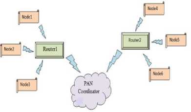
Fig.1. ZigBee WPAN
When a number of nodes move across a group leader or router and base station or pan coordinator; exchanges of a number of handshaking are performed that generated traffic and delivered to this traffic should be nearly seamlessly.
-
II. Overview of Zigbee Network
In 1998, ZigBee was developed; in 2003, it was standardized; in 2006, it was revised. The name ZigBee came from the honeybee that use waggle kind of dance for communication. Radio and Microcontrollers are integrated in the ZigBee chips which have flash memory of 60-250 KB. ZigBee standard is maintained and published by ZigBee alliance. First two layers i.e. PHY and MAC layer is maintained and published by a standard of IEEE 802.15.4. IEEE 802.15.4 is a standard that is used by ZigBee for WPAN that tells how a coordinator is associated and disassociated and how to convey information between coordinator and end device.
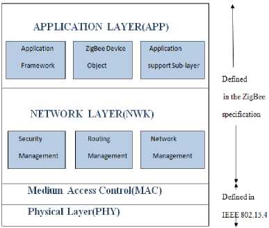
Fig.2. ZigBee Stack Protocol
First two layers i.e. PHY and MAC layer is maintained and published by a standard of IEEE 802.15.4. IEEE 802.15.4 is a standard that is used by ZigBee for WPAN that tells how a coordinator is associated and disassociated and how to convey information between coordinator and end device.
Table 1. ZigBee Frequency Band
|
Frequency Band |
Baud Rate |
Modulation |
Channel Number |
Area Range |
Geographical |
|
868 MHz |
20 Kbps |
BPSK. |
1 |
10-70 meters |
Europe |
|
902-928 MHz |
40 Kbps |
BPSK |
1-10 |
10-70 meters |
America, Australia |
|
2.4 GHz |
250 Kbps |
QPSK |
11-26 |
10-70 meters |
Global |
In ZigBee Technology, Different data rates are used for different frequency range that is fixed as 250 Kbps at the 2.4GHz Frequency Band 40 Kbps @ 902-918MHz Frequency Band 20 Kbps @ 868 MHz Frequency Band Transmission range is up to 70 meter. 16 channels at the 2.4 GHz band; 10 channels at the 902-918 MHz; 1 channel at the 868 MHz are used.
ZigBee power consumption and Bandwidth are generally lower than Bluetooth or WI-FI networks. Speed is the another advantage of ZigBee devices with which the new nodes can be joined to the network in 30 mSec; while a sleeping node wakes up in 15 mSec, where upon communication can be begin with other nodes; this aspect might be essential in several industrial applications.
-
A. IEEE 802.15.4 Standard
IEEE 802.15.4 is a standard that is used with ZigBee Specification for implementing LR-WPAN (Low-rate Wireless Personal Area Network) that is used for wireless communication. It defines how a node is linked to a coordinator and detached from a coordinator and how a message is transferred b/w a coordinator and device. IEEE 802.15.4 Standard is also designed to achieve low power using the DSSS (Direct Sequence Spread Spectrum). FHSS (Frequency Hoped Spread Spectrum) takes more power than DSSS). Lowest two layer i.e. PHY layer and MAC layer are defined by this standard.
Physical (PHY) Layer: Two services i.e. PHY data service and PHY management service are provided by this layer. Data service of PHY layer provides transmission and reception of (PPDUs) across radio channel of physical layer.
Medium Access Control (MAC) Layer: Two services i.e. MAC data services and MAC management service are provided by this layer. MAC data services provide communication and response of MAC Protocol Data Units (MPDUs) across the data services of PHY layer.
MAC Layer of IEEE 802.15.4 supports two type of transmission modes beacon mode and non-beacon mode in the beacon enabled network and non-beacon enabled network respectively.
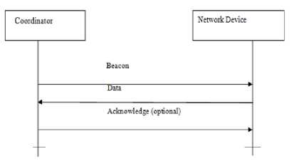
Fig.3. Beacon Enabled Network
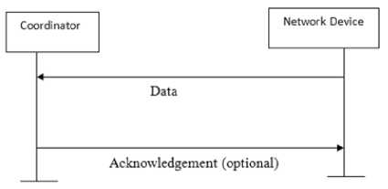
Fig.4. Non-Beacon Enabled Network
IEEE 802.15.4 provides only Star-Based Topology in beacon enabled network and its extension has proposed to Cluster-Tree Topology by ZigBee Specification. Beacon enabled network is used for saving energy using low duty cycle. Cluster Tree Topology is supported by Beacon enabled network. Beacon is used to begin and end of Superframe, declare the existence of a WPAN coordinator, tell pending information in WPAN coordinator and synchronizing with other devices. When main concerns are efficiency of energy and timeliness, beacon enabled network is used.
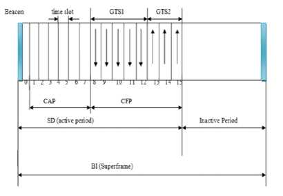
Fig.5. Superframe Structure
In IEEE 802.15.4’s beacon enabled mode, two parameters i.e. SO (Superframe Order) and BO (Beacon Order) are employed in each node which defines SD (Superframe Duration) and BI (Beacon Interval) respectively.
-
• BI (Beacon Interval) = Base Superframe Duration * 2BO; For 0<=SCK=BO<=14 Here, SO = Superframe Order
BO = Beacon Order
-
• SD (Superframe Duration) = Base Superframe Duration * 2SO ; For 0<=SO<=BO<=14
-
• Base Superframe Duration = 15.36 mSec (assuming the 2.4 GHz frequency band and 250 kbps of data rate)
-
• Duty Cycle is the ratio of SD to BI.
BI (Beacon Interval) is the time b/w two successive beacons that contain Active period and Inactive period. Between the beacons, nodes may sleep thus their duty cycle and battery life are lowering and extending respectively. Beacon Intervals (BIs) depend on the data rate. BIs may range from 15.36 mSec to 251.65824 seconds at the 250 Kbit/s, from 24 mSec to 393.216 seconds at the 40 Kbit/s and from 48 mSec to 786.432 seconds at the 20 Kbit/s.
In active period, minimum numbers of symbols are denoted by Base Superframe Duration i.e. 960 symbols. Fig. 5 shows an example of Superframe Structure. Each Superframe Duration’s active period consists of Beacon, Contention Access Period (CAP) and Contention Free Period (CFP). Active Period is called as Superframe Duration and a Base Slot Duration * 2 SO symbols are a length of one slot where in a slot, minimum number of symbols is represented by a Base Slot Duration i.e. 60 symbols.
Superframe Duration (SD) consists of 16 equal time slots which are used for transmission. SD is further divided in two parts i.e. CAP and CFP. CAP (Contention Access Period) uses slotted CSMA/CA Mechanism for best-effort data delivery. CSMA/CA Mechanism is used to access radio channel and radio channel access is controlled by IEEE 802.15.4. Optional CFP (Contention Free Period) support time bound data delivery which supports up to 7 GTSs (Granted Time Slots). Each GTS may transfer information either transmit direction i.e. upstream flow (from Child Node to Parent Router) or receive direction i.e. downstream flow (from Parent Router to Child Node).
SO and BO Parameters should be equal for all Superframes on a WPAN in IEEE 802.15.4 Standard. During active portion of a Superframe, any data sent to devices and all devices interact only with PAN. To avoid the collision, when two devices are sending information or data at the same time; a CSMA-CA Protocol is used. During non -transmission of data, nodes are allowed to sleep for much longer periods in a network. Nodes take minimum time to awake from sleeping mode and to get into sleeping mode.
Beacon enable network is used for consuming power. Coordinator uses data frames to transmit beacon. Beacon is used in the first slot of Superframe. It is used to start Superframe and to synchronize devices. It is also used to pending data in the coordinator. It wakes up end devices when it listen their address and go back for sleep when they don’t get it.
The MAC layer’s features are channel access, beacon management, GTS management, frame delivery acknowledgement, frame validation, association and disassociation
-
B. ZigBee Alliance
ZigBee alliance creates a ZigBee specification that defines how various network topologies with interoperable application profile and features of data security are build. ZigBee alliance provides ZigBee standard that is consist of two layer i.e. NWK layer and APP layer. These layers consist on the top of PHY and MAC layers.
Network (NWK) Layer : It is responsible to establish a networks and management, self-repair function, self configuration, add or leave a node in the network, discard or receive other nodes, security, support routing algorithm, discovering 1-hop neighbours, storing information of neighbour and different network topologies.
Application (APP) Layer: This layer provides ZigBee device objects and application objects. Network communication realization b/w different devices, call for APP layer’s protocol to provides control application and setting and application to access information services are objectives of this layer. The top layer of the ZigBee protocol stack is consisted of the Application Framework, ZigBee Device Objects (ZDOs), and Application Support (APS) Sub layer.
Three types of devices that can be mobile or static in nature are used to design a ZigBee network i.e.
-
1) PAN coordinator
-
2) Router
-
3) End devices
ZigBee devices are designed as Full function devices (FFDs) and reduced function devices (RFDs) and three network topologies i.e. Star, Mesh and Cluster-Tree are used to arrange these devices in ZigBee WPAN.
Some ZigBee Network applications are as:
-
• Home and Building Control
-
• Automation
-
• Industry control
-
• Security
-
• Remote Control
-
• Wireless sensor network
-
• Medical control
-
• Interactive toys
ZigBee Technology is latest technology that is used for above applications because of it offers long battery life, low cost of system, high reliability, low power consumption.
-
III. System Model
In this work, following aspects are covered:
-
• Group Formation
-
• Selection of Group Leader
-
• Soft Hand-off Mechanism
-
• Group Based Communication
-
A. Network Topology
A network is separated in to a number of small Subnetworks to cover a large area of network. The communication between every kind of nodes is performed wirelessly within the network. In term of wireless communication between nodes, two level hierarchies are created. One hierarchy is from end device to router and second is from router to PAN coordinator.
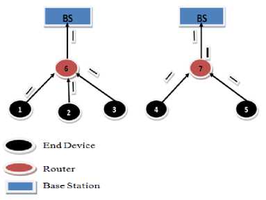
Fig.6. Aggregative Communication
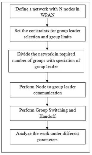
Fig.7. Proposed Model
Here cluster-tree topology is used. Implementation of cluster-tree topology is simple. Information or data is aggregated from one node to another node and moves to all type of nodes in the network. Aggregative communication is passed to PAN coordinator. All information or data is gathered from normal node and then this information or data is forwarded to PAN coordinator. Router is a medium to convey information or data from end node to PAN coordinator.
In fig. 6, End Devices are sensing nodes that sense information from external source and transmit to router. Routers are act as platforms that have greater storage and processing capabilities. These nodes are full function devices which has more capabilities more than reduced function devices. These nodes receive data from multiple normal nodes and then gather them and convey to next hop. Base station or PAN coordinator is always remains fixed. It received information from router. It needs more memory and processing capabilities than router and end devices because it performs maintenance, initialization and control functions.
-
B. The Proposed Model
The work is here defined based on parametric analysis. The parameters considered in this work are
-
1) Velocity
-
2) Connectivity Analysis
-
3) Load
-
C. Scenario Generation
Network parameters setting is the first requirement to work with network application which is based on network communication is performed.
Table 2. Network Parameters
|
Parameters |
Specifications |
|
Area Size |
100 meters* 100 meters |
|
Number of Nodes |
100 |
|
Communication Range |
30 meters |
|
Number of Base Station |
4 |
|
Range of Base Station |
35 meters |
|
Communication Round |
100 |
|
Group Mobility |
Yes |
|
Inter Group Communication |
Yes |
|
Intra Group Communication |
Yes |
|
Topology |
Cluster-Tree Topology |
A WPAN is separated into a number of Sub-Networks in which Cluster-Tree Topology is used. Here four coordinators are used. These coordinators cover a specific range. These act as a base station. It is represented by triangular. A number of groups are formed within SubNetwork. Each group has a group leader that is called as aggregator. Members of group are called end devices or normal nodes. When a node is travelled from a group or a group is travelled from a base station to another base station; soft hand-off is used. From this process, the communication is optimized.
-
D. Network Generation
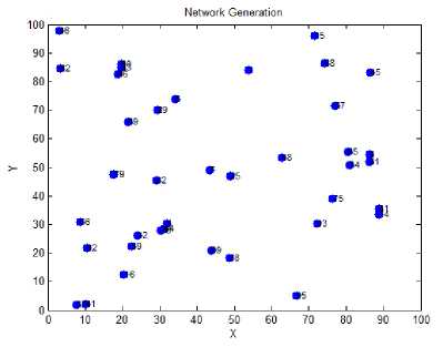
Fig.8. Network Generator
Fig.8. is showing the network with random placement of nodes. The network area is 100 x100 meters and nodes are distributed at random position. Here nodes are the smart sensor nodes defined under mobility vector. Figure is showing the geographical separation of the network with specification of base stations in the network. The network is here defined with specification of base stations with relative range. The triangular shapes are here representing the base station for the network and the larger red circles are showing the base stations. The hand off is here provided b/w the base stations. The nodes are able to perform cooperative communication even when the network is defined with integrated group and area controllers.
-
IV. Proposed Algorithm
GroupMobility(WPANNodes)
/*The wireless personal area network is here defined in limited area. The algorithm is defined to generate the groups and to perform the inter-group communication and intra group communication under multiple parameters. */
{
Set Network Decision Vector for effective the network formation
-
a. SThreshold
-
b. EThreshold
-
c. LThreshold
[The SThreshold for sensing limit, EThreshold for energy restriction and LThreshold for load restrictions are defined for the network]
[Process All Wireless Sensor Nodes]
{
[Analyze Each node respective to ith node]
{ if(Distance(WPANNodes(i),WPANNodes(j))< SThreshold)
[If the node is within the sensing range]
{
C=C+1
[Identify the nodes present in the same group ]
}
} if(C>LThreshold)
[Check for the Group Load Limit]
{
Set WPANNodes(i).Type=GH
[The group head is identified]
}
[Process All Sensor Nodes]
{ if(Distance(WPANNodes(i),WPANNodes(j))<
SThreshold)
[If the node is present within the sensing range]
{
WPANNodes(j).GH=WPANNodes(i)
[Set the group head for each node]
PerformIntraCommunication(WPANNodes(i),
WPANNodes(j))
[Perform the intra communication b/w the node and the group head]
if(Error)
[Idenitfy if the Communication Failed]
{
Set ErrorCount=ErrorCount+1
[Identify the Error Count in the communication] } else
{
Set Comm=Comm+1
Perform the Successfule communication]
} if(Distance(WPANNodes(i),WPANNodes(j))>
S Range)
[Identify the requirement of handoff]
{
Print “Handoff Performed”
Set WPANNodes(j).GH=0
[Identify the feasibile base station for communication]
}
}
-
V. Experiment Results
-
A. Existing Approach
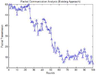
Fig.9. Packet Communication Analysis
Fig.9. is showing the packet transmission over the network including the inter group and intra group communication. The communication is here performed for 100 rounds. The figure is showing the up and down in communication. When the group switching is performed or the hand off is performed, the packet communication is dropped.
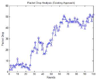
Fig.10. Packet Drop Analysis
Fig.10. is showing the packet drop over the network including the inter group and intra group communication. The communication is here performed for 100 rounds. The figure is showing the up and down in communication. When the group switching is performed or the hand off is performed, packet drop is increased. Figure is showing that the packet drop in existing approach is high.
Fig.11. is showing the packet transmission and packet drop analysis over the network including the inter group and intra group communication. The communication is here performed for 100 rounds. The higher line is here showing the packet communication and lower line is showing the packet drop. The figure is showing the packet communication is higher than packet drop. In some cases, when the switching is performed, the packet communication is degraded and loss increased.
-
B. Proposed Approach
In the proposed work, the energy, distance, Load and destiny based groups are formed and the group adaptive communication is performed. The node to group leader communication is applied. The packet communication here represents the successful packet communication performed in the network. But if the node comes outside the group, it can result the packet drop.
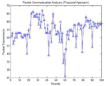
Fig.12. Packet Communication Analysis
Fig.12 is showing the packet transmission successfully performed over the network including the inter group and intra group communication. The communication is here performed for 100 rounds. The figure is showing the up and down in communication. Inter group and intra group communication are performed in the work. When inter group communication is performed. More packets are transmitted successfully and very less packets are dropped. But when inter group communication is performed, nodes move outside the coverage area of its base station from which handoff or group switch is performed due to which packet communication is dropped.
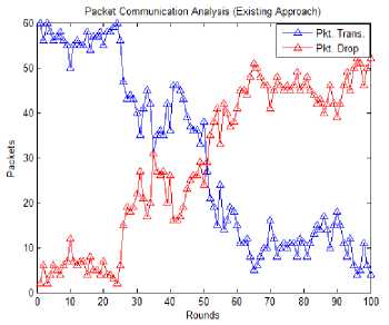
Fig.11. Packet Communication Analysis
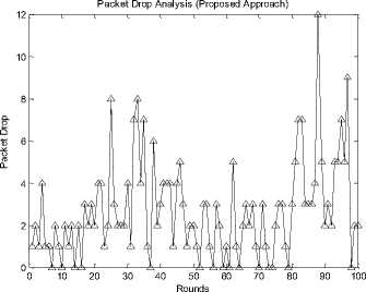
Fig.13. Packet Drop Analysis
Fig.13. is showing the packet drop over the network including the inter group and intra group communication. The communication is here performed for 100 rounds. The Figure is showing the up and down in communication. When the group switching is performed or the hand off is performed, the packet drop is increased.
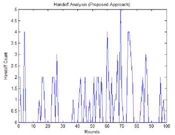
Fig.14. Handoff Analysis
Fig.14. is showing the handoff count results in case of proposed work. The communication is here performed for 100 rounds. The figure shows that as the node moves outside the geographical coverage of base station, the handoff is performed. Higher the number of handoff more chances of data drop.
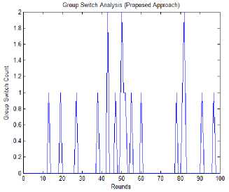
Fig.15. Group Switch Analysis
Fig.15. is showing the Group switches count results in case of proposed work. The communication is here performed for 100 rounds. The figure shows that as the node moves outside the geographical coverage of group, the group switch is performed. Higher the number of group switches more chances of data drop.
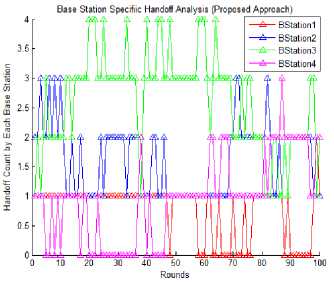
Fig.16. Base Station Specific Handoff Analysis
Fig.16. is showing the base station specific switch count results in case of proposed work. The communication is here performed for 100 rounds. The figure shows that as the node moves outside the geographical coverage of group, the group switch and handoff is performed. Higher the number of group switches more chances of data drop.
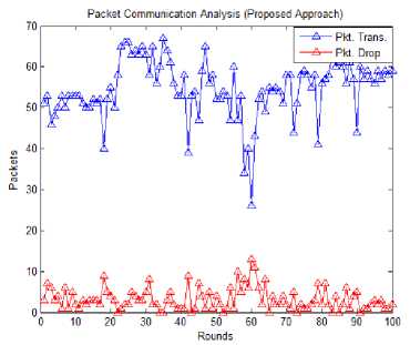
Fig.17. Packet Communication Analysis
Fig.17. is showing the packet drop and packet transmission analysis over the network including the inter group and intra group communication. The communication is here performed for 100 rounds. The higher line is here showing the packet communication and lower line is showing the packet drop. The figure is showing the packet communication is higher than packet drop. In some cases, when the switching is performed, the packet communication is degraded and loss increased.
C. Comparisons between Existing and Proposed Approach
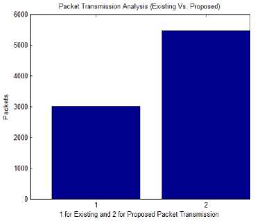
Fig.18. Packet Transmission Analysis
Fig.18. is showing the comparative analysis on existing and proposed work in terms of packet communication. The figure shows that the work has overall improved the packet communication over the network. In the existing work, the energy and distance based groups are formed. No consideration to load vector or density is considered in existing work.
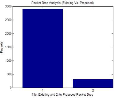
Fig.19. Packet Drop Analysis
Fig.19. is showing the comparative analysis on existing and proposed work in terms of packet loss. The figure shows that the work has overall reduced the packet loss over the network. In the existing work, the energy and distance based groups are formed. No consideration to load vector or density is considered in existing work.
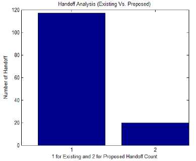
Fig.20. Handoff Analysis
Fig.20. is showing the comparative analysis on existing and proposed work in terms of handoff. The figure shows that the work has overall reduced the handoff because of the density adaptive communication is formed. In the existing work, the energy and distance based groups are formed. No consideration to load vector or density is considered in existing work.
Group Switch Analysis (Existing Vs. Proposed)
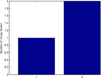
1 for Existing and 2 for Proposed Group Switch Count
Fig.21. Group Switch Analysis
Fig.21. is showing the comparative analysis on existing and proposed work in terms of group switching. The figure shows that the work has overall more group switching but handoff is reduced because of the density adaptive communication is formed. In the existing work, the energy and distance based groups are formed. No consideration to load vector or density is considered in existing work.
-
VI. Conclusions
The concept of group mobility is included in WPAN to improve communication. In the network, sensor nodes that are known as smart nodes are used. All parameters of the network are set according to ZigBee Technology. A number of groups are formed under the mobility vector. After that we performed inter and intra group communication. During communication, hand-off is used whenever node switches outside geographical area of group or outside the geographical area of base station. Communication throughput is improved and communication loss is reduced by using soft hand-0ff and by using density adaptive communication.
References Optimized Communication of Group Mobility in WPAN
- Patrick, Jae Sheung Shin, BharatMadan, Shashi Phoha, Thomas La Porta, "Efficient Group Mobility for Heterogeneous Sensor Networks", DAAD19-01-1-0504 and NSF Grant CNS-0453830, DARPA and NSF.
- Falk-Moritz Schaefer, Tobias Grob and Rudiger Kays, "Energy Consumption of 6LoWPAN and ZigBee in Home Automation Networks", 978-1-4799-0543-0/13, 2013 IEEE.
- M. Barathi Kannamma, B. Chanthini, D. Manivannan, "Controlling and Monitoring Process in Industrial Automation using ZigBee", 978-1-4673-6217-7/13, 2013 IEEE.
- Adam Dahlstrom and Ramesh Rajagopalan, "Performance Analysis of. Routing Protocols in ZigBee Non- Beacon Enabled WSNs", Internet of Things: RFIDs, WSNs and beyond, 978-1-4673-3133-3/13, 2013 IEEE.
- Ching-Lung Lin, Yuan-Chuen Hwang, Hsueh-Hsien Chang, Ching-Feng Lin, "Power Measurement with Economic Management by Using ZigBee RF Technology", 10th International Conference on e-Business Engineering, 978-0-7695-5111-1/13, 2013 IEEE.
- Lei Zhou, Ying Zhu, Ai Chen, "A Simulation Platform for ZigBee-UMTS Hybrid Networks", IEEE communications letters, Vol. 17, No.2, 1089-7798/13, 2013 IEEE.
- Alexandru-Corneliu Olteanu, George-Daniel Oprina, Nicolae Tapus and Sven Zeisberg, "Enabling mobile devices for home automation using ZigBee", 19th International Conference on Control Systems and Computer Science, 978-0-7695-4980-4/13, 2013 IEEE.
- D. Nowak, "Integration of ZigBee and IEC 61850 networks for a substation automation system-Meeting time requirements under heavily loaded radio channel conditions", 4th IEEE PES Innovative Smart Grid Technologies Europe (ISGT Europe), 2013 IEEE.
- Suratsavadee K. Korkua and Kamon Thinsurat, "Design of ZigBee based WSN for Smart Demand Responsive Home Energy Management System", 13th International Symposium on Communications and Information Technologies (ISCIT), 978-1-4673-5580-3/13, 2013 IEEE.
- Jianyu Niu, Ruonan Zhang, Guangde Wang, Shuguang Li and Shuai Wan, "Design and Experimental Evaluation of Long-distance and High-Mobility ZigBee Transceivers for WSNs", the First IEEE ICCC International Workshop on Internet of Things, 978-1-4799-1403-6/13, 2013 IEEE.
- Hoi Yan Tung, "The Generic Design of a High-Traffic Advanced Metering Infrastructure Using ZigBee", IEEE transactions on industrial informatics, 1551-3203, 2013 IEEE.
- Mirko Franceschinis, Claudio Pastrone, Maurizio A. Spirito, Claudio Borean, "On the Performance of ZigBee Pro and ZigBee IP in IEEE 802.15.4 Networks", Sixth International Workshop on Selected Topics in Mobile and Wireless Computing, 978-1-4799-0428-0/13, 2013 IEEE.
- Meng-Shiuan Pan, Ping-Lin Liu, and Chien-Fu Cheng, "Convergecast in ZigBee Tree-Based Wireless Sensor Networks", IEEE Wireless Communications and Networking Conference (WCNC), 978-1-4673-5939-9/13, 2013 IEEE.
- Luca Secci and Chiara Buratti, "Reducing Traffic Congestion in ZigBee Networks: Experimental Results", 978-1-4673-2480-9/13, 2013 IEEE.
- Hua Qin and Wensheng Zhang, "ZigBee-Assisted Power Saving for More Efficient and Sustainable Ad Hoc Networks", IEEE transactions on wireless communications, 1536-1276/13, 2013.
