Optimizing Concentric Circular Antenna Arrays for High-Altitude Platforms Wireless Sensor Networks

Author: Yasser Albagory, Omar Said
Journal: International Journal of Computer Network and Information Security(IJCNIS) @ijcnis
Article in issue: 5 vol.6, 2014.
Free access
Wireless Sensor Networks (WSN) has gained interest in many applications and it becomes important to improve its performance. Antennas and communication performance are most important issues of WSN. In this paper, an adaptive concentric circular array (CCA) is proposed to improve the link between the sink and sensor nodes. This technique is applied to the new High – Altitude Platform (HAP) Wireless Sensor Network (WSN). The proposed array technique is applied for two coverage scenarios; a wider coverage cell of 30 km radius and a smaller cell of 8 km radius. The feasibility of the link is discussed where it shows the possibility of communications between the HAP sink station and sensor nodes located on the ground. The proposed CCA array is optimized using a modified Dolph-Chebyshev feeding function. A comparison with conventional antenna models in literature shows that the link performance in terms of bit energy to noise power spectral density ratio can be improved by up to 11.37 dB for cells of 8 km radius and 16.8 dB in the case of 30 km radius cells that make the link at 2.4 GHz feasible and realizable compared to using conventional antenna techniques.
High altitude platforms, wireless sensor network, directional antennas, concentric circular arrays
Short address: https://sciup.org/15011298
IDR: 15011298
Text of the scientific article Optimizing Concentric Circular Antenna Arrays for High-Altitude Platforms Wireless Sensor Networks
Recently, the importance of Wireless Sensor Network (WSN) has gained attention where it is applied in many applications including industrial manufacturing, military, agriculture, health care, and security [1-4]. The structure of this network contains a number of remote sensors that measure some data and forward it wirelessly to a collection point called sink. The distance between the sensors and the sink depends on the communication environment and the power available for sensors which usually comes from batteries. There are many challenges for the WSN such as the limited battery life time, wireless communication performance, routing and data security. The energy of sensors is the most important problem due to network-lifetime maximization target. Another main issue regarding WSN is the breadth of the coverage which depends on the communication technology applied between these sensor nodes and sinks especially the antenna types. The ground-based WSN has a very limited communication range due to the channel impairments including multipath fading problems. The existing sensor technology has limited sink coverage to few meters due to the limited battery life time. The coverage range and battery life time can be extended by changing the type of communications channel to reduce the fading problem and namely using the free-space or line-of-sight model. Recently, the feasibility of covering large area WSN [5] with High-Altitude Platforms (HAPs) has been proved for the existing sensors technologies without using sensor power enhancements or external power sources and the coverage radius may extend to several tenses of kilometers. The HAP is an aerial platform that operates in a quasi-stationary position as defined in Radio Regulations (RR) No. S1.66A as “a station located on an object at an altitude of 20 to 50 km and at a specified, nominal, fixed point relative to the earth” and carrying communications payloads. The HAPs provide many attractive features and superior performance compared to the conventional terrestrial and satellite technology such as the line-of-sight communications, lower transmission power and reduced time delays [6-16]. The HAP makes it possible for establishing Wide-Area Wireless Sensor Network (WAWSN) where several hundreds of kilometers breadth can be covered by a single HAP. On the other hand, we can further improve the link performance of the HAP WSN by configuring the antennas at the HAP and optimizing it for maximum performance improvement. The antennas used for HAP communications include fixed spot beam antennas or adaptive antenna arrays, therefore in this paper, the two antenna types are examined and the antenna array in the form of concentric circular arrays is optimized to improve the HAP-WSN communication performance.
The paper is arranged as follows; section II describes the structure of the HAP-WSN and section III provides the communications link equation used for evaluating the performance of HAP-WSN. Section IV proposes the adaptive antenna technique for HAP-WSN coverage as well as the conventional antenna and section V provides simulation results for both the conventional antenna and the proposed antenna array technique. Finally section VI concludes the paper.
-
II. Structure of HAP - WSN
HAP is an aerial station that is capable to provide a variety of communications applications, monitoring, surveillance, and even in noncommercial military applications. Recently, the HAP provides a good candidate for WSN which may be used in many scenarios. In this paper the HAP acts as a global sink station that collects the ground sensors data either from a large area or in a cellular fashion as shown in Fig. 1. The use of HAP as a sink station provides not only a large area coverage, but also a security on the sink itself as it is highly elevated. In addition, the HAP acts as a global sink station that can provide coverage up to 1000 km diameter when located at 20 km altitude. The structure shown in Fig. 1 can be modified to include sub-sink stations on ground which collects data from nearby sensor nodes and forward it to the global HAP sink. This configuration is suitable for cellular WSN but on the other hand is not secure enough as the sub-sinks are located on the ground. The other proposed scheme is direct transmission from ground sensor nodes to the global HAP sink which will be proved in this paper using the same sensor technology and without the need to increase either the transmitted power from them or the transmitting antennas.
In the following section, we will describe the HAP-WSN link equation that will be useful in evaluating the system performance.
-
III. Link Equations and System Evaluation for HAP - WSN
The quality of link between a HAP sink and the ground sensors depends on the environment where the sensors exist, the elevation angle between the HAP and the sensors or the breadth of the coverage, transmitting frequency, bit rate and the distance of the link. Additional link parameters also apply such as the transmitting power, transmit and receive antenna gains and the atmospheric conditions. To evaluate the system performance we can rely on the bit energy-to- noise power spectral density which is a main parameter affecting the probability of error in the system according to the modulation scheme applied. To determine this ration we may first define the received power at the HAP sensor as follows:
Рт = PtGs Gh / P l (1)
where Pt is the sensor transmitting power, Gs is the sensor antenna gain, G h is the HAP antenna gain and PL is the propagation loss between the sensors and the HAP. The last equation may be expressed in dB as:
Pr [dB ] = Pt [dB ] + Gs [dB ] + G h [dB ] - PL [dB ] (2)
HAP Sink
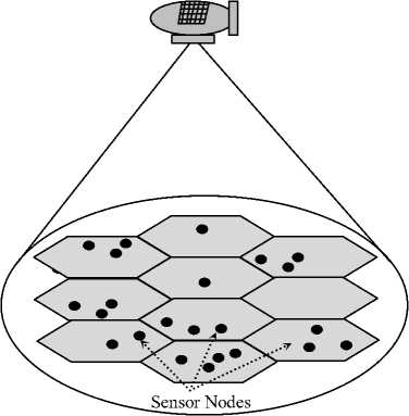
Fig 1: HAP-WSN structure
The propagation loss includes both the loss due to the distance and the loss due to shadowing effect:
P L (d) [dB] = P L (do) [dB] + 10n log( d/d o ) + X q (3)
where n is the pathloss exponent, d o is a reference distance and d in the separation distance between HAP sink and sensor node.
The propagation loss PL(do) in dB is calculated from the following equation:
P L ( d o ) = 20 log (4 π d /λ) (4)
The additional loss Xq represents the loss due to the shadowing effects and is characterized as a Gaussian random variable in dB with zero mean and standard deviation sigma in dB also.
The value of n and sigma depend on the propagation environment where for free space propagation n = 2 and a typical value of sigma in HAP – WSN is 2 dB.
The received power at the HAP sink is not the only key parameter as a performance measure but another very important quantity denoted as the ration of the bit energy to noise spectral density (Eb/No) which determines with the modulation scheme the probability of bit error. This ration is given by:
E b /N o ( x,y ) = P t A s A H /N o R b P L (5)
where Rb is the bit rate and (x,y) is the location of the sensor node as shown in Fig. 2 which determines the distance d from the following relation:
d = ^x2 + у2 + z2
V m
The Eb/No (x,y) may be expressed in dB as follows:
E b /N o [dB] = P t [dB] + G s [dB] + G H [dB] - P L [dB] – N o [dB] – R b [dB] (7)
As shown from (5) and (7), Eb/No can be improved by increasing the antenna gain either in the transmitting sensor node or at the HAP sink. Increasing antenna gain at the sensor node is physically very difficult due to the increased antenna size and hence the overall sensor volume which in many cases is undesirable. At the HAP sink, the large size and power make it possible to deploy large antennas or antenna arrays which can be optimized to improve the quality of link in HAP – WSN as will be discussed in the next section.
2n
N m
and the elements in this ring are therefore located with an azimuth angle measured from the x-axis given by:
Assuming an observation point P located at a distance r form the origin, the measured far field at this point will be:
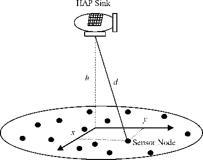
Fig 2: HAP-WSN sensor coordinates and link distances
jkr M Nm
e ( r , 6 , ф ) = — xx wm e msin 6(Ф-Ф "” ) (io)
Г m = 1 n = 1
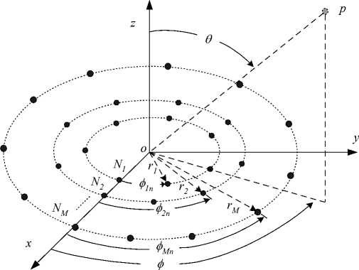
Fig 3: Geometry of CCA
IV. The Proposed Concentric Circular Arrays Technique for HAP Sink Coverage
In this section, the array configuration and the proposed beamforming technique at the HAP sink will be demonstrated. There are a variety of antenna arrays for beamforming applications such as the planar twodimensional array, circular arrays and the concentric circular arrays. The last array configuration has interested features such as the capability of symmetrical beamforming in all azimuth range (i.e. 360 degrees beamforming) with reduced sidelobe levels [17-20]. Therefore, in this paper we will use this array configuration to provide both gain and beamwidth requirements. The arrangement of elements in CCA contains multiple concentric circular rings which differ in radius and number of elements and this gives arise to different radiation patterns. Figure 3 shows the configuration of CCA where there are M concentric circular rings. The mth ring has a radius rm and a number of elements N m where m = 1,2,." M . Assuming that the elements are uniformly spaced within the ring so it has an element angular separation given by:
where t-Z^ is the wave number and w is the mfi
X excitation coefficient (amplitude and phase) of the mnth element. We can deduce an expression for the array steering matrix by defining the array steering vector for a single ring and extending the analysis for the whole array. The array steering vector for the mth ring will be:
S cm ( 6 , Ф ) = [ e
jkrm sin 6 cos ( ф - ф m 1 )
e jkrm sin 6 cos ( ф - ф m 2 )
jkrm sin 6 cos( ф - фmN ) T
... e m ]
and the array steering matrix can be formulated as:
Generally, it is possible for the rings to be of different number of elements and the array steering vectors will not be of the same length, therefore we append lower dimension vectors with zeros.
Each of the number of elements in each ring, the interelement spacing and the inter-ring spacing will affect the array performance such as the beamwidth and sidelobe
levels. We consider here the array that has almost
Ц 2
element-separation. The mnth element in the matrix
3- Finally, the CCA ring coefficients will be given by [82]:
A CCA ( 0 , фф
can be written as:
A CCAmn ( 0 , 9 ) = е"^sin ” cos ' "" m 1
W
m
where
M
z "i i=1
M
z Xi"i
V i = 1
X m
dZ
m
2 n r m
N ^ m
is the normalized interelement-arc-separation of the mth ring. The array gain will be determined from the following equation:
G ( 0 , ф ) = SUM { w ( 0 , ф ) H A CA ( 0 , ф ) } (15)
where the SUM operator is the summation of all elements in the resulted matrix W ( 0 , ф ) H Acc”0ф >) , H is the complex conjugate transpose or Hermitian operator and W ( 0 , ф ) is the weight matrix that controls the amplitudes and phases of the input currents.
The coverage beam will be controlled using a modified version of the Dolph-Chebyshev coefficients that were applied to linear one-dimensional arrays [21].
Assuming that we have M rings CCA, and then we design a one-dimensional array of 2M elements of a certain sidelobe level R o and obtain the array coefficients from the following design steps:
1- Find the value of z from the following equation:
1/ p 1/ p
z = 0.5^(Ro + Rr--1) +(Ro -Rr--1) j (16)
where R in this equation is in ratio and p = 2 M - 1
2- The normalized amplitude coefficient of the mth element in the one-dimensional Dolph-Chebyshev array is calculated as [71]:
X m
m M - q
Z ( - 1 ) z o 2 q - 1
q = m
(q + M - 2)!(2M -1)(q - m)!(q + m -1)!(M - q)
m M - q
q = 1
(q + M - 2)!( 2 M-1)(q -1)!( q + m-1)!( M - q)
where m = 1,2,..., M
The resulted sidelobe level of the CCA using (18) provides sidelobe levels that are different from R o due to the change in the array configuration, but actually when we vary the value of Ro the sidelobe levels of the weighted CCA vary and the sidelobe levels reaches a floor at R o = 80 dB as demonstrated in [22]. The main purpose here is to provide the required coverage radius by optimizing the array weights, the interelement spacing distances, innermost ring size and the number of rings. The cell boundary can be defined by several limits such as the 3 dB or 10 dB power contour. We will apply the 10 dB contour as the cell boundary as in [23] for the purpose of comparison. The antenna model developed by [23] was adopted where the directivity pattern of the aperture antenna was modeled by:
D (0) = (cos(0))"-^|) (19)
2(2 cosCV()?5))
Therefore, optimizing this function to find the value of n will provide a good approximation to the real radiation pattern. The power pattern in (19) is designed for two types of cells; a 30 km radius and another smaller cell of 8 km to examine wide coverage and possibility of cellular coverage respectively. The power gain profile for the two cases is shown in Fig. 4 where the first corresponds to the 8 km cell and the lower curve corresponds to the conventional spot-beam antenna design as in (19) while the second upper curve is for the proposed optimized CCA that gives the same power profile but at much higher boresight gain.
In addition, Fig. 5 provides the power gain profile for the two antenna types designed for 30 km HAP cell. In this figure, the optimized CCA provides an increased higher boresight gain by about 17 dB which is an incredible amount of power gain difference and should reflect an improvement in the HAP-WSN performance.
Figure 6 and 7 display the power gain profile on the ground surface for the optimized CCA and for the 8 and 30 km HAP cells respectively.
The array parameters for the design of these two cells designs are displayed in Table 1 where the optimized CCA has weighting distribution given in (18) and optimized in N1, M, and am to give the required power gain profile.
Table 1: Design parameters for spot-beam and CCA
|
h = 17 km |
8 km WSN-HAP Cell |
30 km WSN-HAP Cell |
||||
|
N 1 |
M |
a m |
N 1 |
M |
a m |
|
|
CCA |
5 |
5 |
0.33 |
4 |
4 |
0.2 |
|
Spot-Beam Antenna |
n = 11.6 |
n = 1.65 |
||||
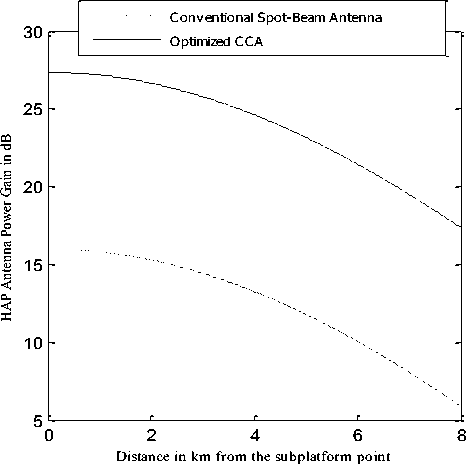
Fig 4: Antenna power gain of conventional spot-beam antenna and optimized CCA for 8 km HAP cell.
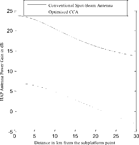
Fig 5: Antenna power gain of conventional spot-beam antenna and optimized CCA for 30 km HAP cell.
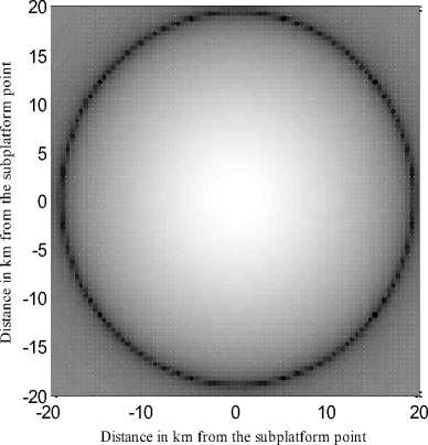
Fig 6: Power gain illuminiation of the optimized CCA designed for 8 km cell.

-10
-20
-30
-40
-50
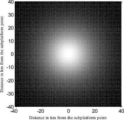
Fig 7: Power gain illuminiation of the optimized CCA designed for 30 km cell.

-
V. Simulations Results
In this section, four case studies are examined to show the feasibility of the proposed optimized CCA technique compared to the conventional spot-beam antenna. The comparison is based on the Eb/No as a performance measure of the HAP-WSN. The sensor nodes are chosen with the same existing technology. The operating frequencies are chosen in the free industrial, scientific and medical (ISM) band. We consider here the same frequencies used in [23] for comparison purpose which are 868 MHz and 2.4 GHz. For the two frequencies, we have two transmitting bit rates; that is 38.4 kb/s at the 868 MHz and 2500 kb/s at the 2400 MHz frequency. The modulation scheme is the binary phase shift keying
(BPSK). In the first case, as shown in Fig. 8, the cell radius is 8 km, the transmitting frequency is 868 kHz and Rb is 38.4 kb/s. The two antenna cases show a possible and feasible link between the HAP sink and the ground sensor nodes. In this case, the optimized CCA shows a better link performance by about 10 dB due to the improved antenna gain. In the second case and for the same cell radius of 8 km, the operating parameters are changed where the frequency is 2400 MHz and the Rb is 250 kb/s. The link performance as shown in Fig. 9 is deteriorated somewhat but still feasible specially in the case of the optimized CCA where the probability of Eb/No to be less than X at X is lowered by values between 0.1 and 0.7. This implies an improvement in the link performance and indicates robustness of the proposed optimized CCA.
The third case is described for the 30 km cells at a transmitting frequency is 868 kHz and Rb is 38.4 kb/s. The performance comparison is shown in Fig. 10 where it is possible for establishing the network in this case with improved performance for the optimized CCA. The last case is at the same cell radius (30 km) but at frequency of 2400 MHz and Rb of 250 kb/s. This case shows the lowest performance HAP-WSN due to the increased bit error resulting from lower Eb/No. In this case as shown in Fig. 11, the link for the conventional antenna is impossible and not feasible as the antenna gain is very weak to provide reasonable Eb/No, while the optimized CCA is able to establish feasible link due to the improved power pattern. Therefore, in all examined cases, the optimized CCA provides better performance and feasible link between the HAP sink and the ground sensor nodes alth h th l di t ti th
Conventional Spot-Beam Antenna Optimized CCA
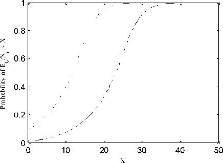
Fig 9: Probability of Eb/No for the two antenna types designed for 8 km cell at 2400 MHz and Rb = 250 kb/s
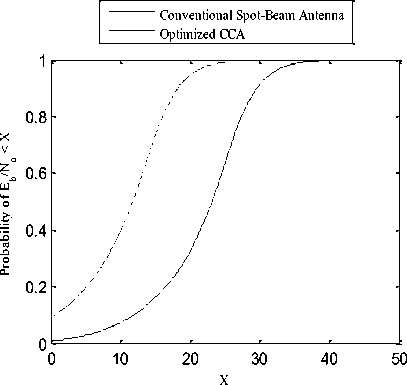
Fig 10: Probability of Eb/No for the two antenna types designed for 30 km cell at 868 MHz and Rb = 38 4 kb/s
Conventional Spot-Beam Antenna Optimized CCA
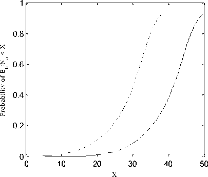
Fig 8: Probability of Eb/No for the two antenna types designed for 8 km cell at 868 MHz and Rb = 38.4 kb/s.
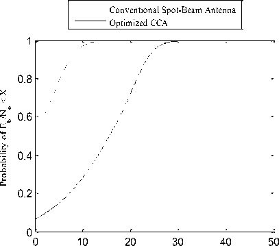
Fig 11: Probability of Eb/No for the two antenna types designed for 30 km cell at 2400 MHz and Rb = 250 kb/s.
-
VI. Conclusions
In this paper, the wireless sensor network has been built using the ambitious technology of high-altitude platforms. The proposed HAP-WSN scenario provides many advantages over the conventional terrestrial or satellite WSN such as the wide coverage and good quality of communications link. The HAP in this scenario acts as a global sink that links and collects data from sensor nodes on the ground. The performance of this system can be improved by improving the quality of link between the sink and the sensor nodes which is achieved in this paper by using modified Dolph-Chebyshev concentric circular arrays. The array is used at the HAP and is optimized to provide better gain and coverage over the required area. The optimization process also minimizes the out-ofcoverage radiation which is important for cellular WSN. Compared with the conventional spot-beam antenna techniques, the proposed modified Dolph-Chebyshev CCA technique guarantees the communication between HAP and sensor nodes at the worst case of 2400 MHz and bit rate of 250kb/s the case that is impossible using the conventional antenna techniques. The simulation results showed that the link performance in terms of bit energy to noise power spectral density ratio can be improved by 11.37 dB for cells of 8 km radius and by 16.8 dB in the case of 30 km radius cells which make the link at 2.4 GHz to be feasible and realizable.
References Optimizing Concentric Circular Antenna Arrays for High-Altitude Platforms Wireless Sensor Networks
- Y. Wang, M. Wilkerson, X. Yu, "Hybrid Sensor Deployment for Surveillance and Target Detection in Wireless Sensor Networks", International Conference on Wireless Communications and Mobile Computing (IWCMC), Istanbul, Turky, pp. 326 – 330, 2011.
- R. Alageswaran, R. Usha, R. Gayathridevi, G. Kiruthika, "Design and implementation of dynamic sink node placement using Particle Swarm Optimization for life time maximization of WSN applications", IEEE International Conference on Advances in Engineering, Science and Management (ICAESM), Nagapattin, India, pp. 552 – 555, 30-31 March 2012.
- J. Salminen, L., Andrey, A. Yla-Jaaski, "Smart Trigger for Ultralow Power and Time Critical WSN Applications", IEEE International Conference on Green Computing and Communications (GreenCom), Besan?on, France, 20-23 Nov. 2012.
- W. Yu , X. Qian, "Design of 3KW Wind and Solar Hybrid Independent Power Supply System for 3G Base Station", International Symposium on Knowledge Acquisition and Modeling, Wuhan, China, pp. 289 - 292, 2009.
- M.F. Urso, M. Mondin, E. Falletti, F. Sellone, S. Arnon, "Self Organizing WSN Collaborative Beamforming for HAP Communications", IEEE GLOBECOM Workshops, LA, USA, pp. 1 – 5, Nov. 30 -Dec. 4 2008.
- A. Mohammed, A. Mehmood, F. Pavlidou and M. Mohorcic “The Role of High-Altitude Platforms (HAPs) in the Wireless Global Connectivity”, Proceedings of the IEEE, Vol. 99, No. 11, pp. 1939 – 1953, Nov. 2011.
- J. Kim, D. Lee, J. Ahn and B. Ku, “Is HAPS Viable for the Next-Generation Telecommunication Platforms in Koria”, EURASIP Journal on Wireless Communications and Networking, Vol. 2008, doi: 1155/2008/596383, 2008.
- S. Karapantazis and F. Pavlidou “Broadband Communications via High-Altitude Platforms: A Survey”, IEEE Communications Surveys & Tutorials, First Quarter 2005, pp. 1-31, 2005.
- P. Pace and G. Aloi “Disaster Monitoring and Mitigation using Aerospace Technologies and Integrated Telecommunication Networks”, IEEE Aeropspace and Electronic Systems Magazine, Vol. 23, No. 4, pp. 3-9, April 2008.
- Yasser Albagory, “A Novel Design of Arbitrary Shaped Cells for Efficient Coverage from High Altitude Platforms", Progress In Electromagnetics Research Letters, Vol. 1, 245- 254, 2008.
- Yasser Albagory Moawad Dessouky, Hamdy Sharshar, “Geometrical Analysis of High Altitude Platforms Cellular Footprint,” Progress In Electromagnetics Research, PIER 67, pp. 263-274, 2007.
- Yasser Albagory, Moawad Dessouky, Hamdy Sharshar, “Design of High Altitude Platforms Cellular Communications,” Progress In Electromagnetics Research, PIER 67, pp. 251-261, 2007.
- A. K. Widiawan and R. Tafazolli, "High Altitude Platform Station (HAPS): A Review of New Infrastructure Development for Future Wireless Communications", International Journal of Wireless Personal Communications, Springer 2006.
- M. Antonini et al., "Stratospheric Relay: Potentialities of New Satellite-High Altitude Platforms Integrated Scenarios", Proceeding IEEE Aerospace Conference, 2003, Mar. 8–15, Vol. 3, pp. 1211–19, Montana, USA, 2003.
- M. Oodo, R. Miura, T. Hori, T. Morisaki, K. Kashiki, and M. Suzuki, "Frequency sharing and compatibility study between fixed service using high altitude platform stations (HAPS) and other services in the 31/28 GHz bands", Proceedings of WPMC 2001, pp. 93–98, 2001.
- Y. Foo, W. Lim, and R. Tafazolli, "Centralized total received power based call admission control for high altitude platform station UMTS", Proceeding of IEEE PIMRC 2002, 2002.
- Yasser Albagory, Moawad Dessouky, Hamdy Sharshar, “Efficient Sidelobe Reduction Technique for Small-Sized Concentric Circular Arrays,” Progress In Electromagnetics Research, PIER 65, pp. 187-200, 2006.
- Yasser Albagory, Moawad Dessouky, Hamdy Sharshar, “A Novel Tapered Beamforming Window for Uniform Concentric Circular Arrays” Journal of Electromagnetic Waves and Applications, JEMWA, Vol. 20, No. 14, pp. 2077-2088, 2006.
- Yasser Albagory, Moawad Dessouky, Hamdy Sharshar, “Optimum Normalized-Gaussian Tapering Window for Side Lobe Reduction in Uniform Concentric Circular Arrays,” Progress In Electromagnetics Research, PIER 69, pp. 35 –46, 2007.
- Yasser Albagory, “Sectorized Hamming Concentric Circular Arrays for Stratospheric Platforms Cellular Design”, International Journal of Computer Network and Information Security, Vol. 5 No. 9, pp. 21-27, 2013.
- C. A. Balanis, Antenna Theory: Analysis and Design, 2nd Edition, John-Wiley & Sons, 1997.
- Yasser Albagory, Moawad Dessouky, Hamdy Sharshar, “An Approach for Dolph-Chebyshev Uniform Concentric Circular Arrays,” Journal of Electromagnetic Waves and Applications, JEMWA, Vol.21, No.6, pp.781 –794,2007.
- Z. Yang, and A. Mohammed, “High Altitude Platforms for Wireless Sensor Network applications”, IEEE International Symposium on Wireless Communication Systems 2008, ISWCS2008, pp. 613-617. 2008.
