Organization of complex testing of the spacecraft command and measuring system

Author: Nozhenkova L.F., Isaeva O.S., Koldyrev A. Yu.
Journal: Сибирский аэрокосмический журнал @vestnik-sibsau
Section: Авиационная и ракетно-космическая техника
Article in issue: 3 т.19, 2018.
Free access
In this article, we present the software for organization of complex testing of a spacecraft’s command and measur- ing system. The command and measuring system is responsible for communication of a spacecraft with the ground con- trol complex. The developed software is designed for the support of interaction between the automated testing complex of a spacecraft and test and control equipment of the command and measuring system. Complex tests include testing of all or a part of conjugate elements of a spacecraft, united in a single system, with simulation of regular and possible non-standard modes of operation. Complex tests of the command and measuring system are carried out using an auto- mated testing complex, the main task of which is transferring of the control commands to the test and control equipment of the command and measuring system. The automated testing complex also receives packages from the test and control equipment containing telemetric information about the state of the on-board systems of a spacecraft. During complex tests of the command and measuring system, the developed software supports the exchange of command and telemetry packages between the automated testing complex and test and control equipment. The developed software is built in the software of the test and control equipment as a subsystem for organizing of complex testing. The subsystem receives commands from the automated testing complex, identifies and sends them to the test and control equipment, in the form of a structure that is understandable to the command and measuring system. For each command, the subsystem produces a receipt of successful identification or of an error if it occurs. The subsys- tem receives telemetry from the command and measuring system, converts it in accordance with the protocols of inter- action and sends it to the automated testing complex. In addition to the command and measuring system’s telemetry, the telemetry of the test and control equipment is sent to the automated testing complex. It contains the parameters of the sensors of various equipment that are part of the hardware and software complex, as well as the parameters required for transmission channels’ settings between the test and control equipment, command and measuring system and other systems of a spacecraft. All actions occurring during the process of complex testing are recorded in the test report. All protocols of tests are saved and can be replayed.
Spacecraft, command and measuring system, complex testing, test and control equipment, telecommands, telemetry
Short address: https://sciup.org/148321864
IDR: 148321864 | UDC: 004.42 | DOI: 10.31772/2587-6066-2018-19-3-510-516
Организация комплексных испытаний командно-измерительной системы космического аппарата
Представлено программное обеспечение для проведения комплексных испытаний командно-измерительной системы космического аппарата. Командно-измерительная система отвечает за коммуникацию космического аппарата с наземным комплексом управления. Разработанное программное обеспечение предназначено для поддержки взаимодействия автоматизированного испытательного комплекса космического аппарата и кон- трольно-проверочной аппаратуры командно-измерительной системы. Комплексные испытания представляют собой тестирование всех или части сопряжённых элементов космического аппарата, объединенных в единую систему, с имитацией штатных и возможных нештатных режимов функционирования. Комплексные испы- тания командно-измерительной системы проводятся с использованием автоматизированного испытательно- го комплекса, основной задачей которого является передача команд управления на контрольно-проверочную аппаратуру командно-измерительной системы. Автоматизированный испытательный комплекс также при- нимает от контрольно-проверочной аппаратуры пакеты телеметрической информации о состоянии борто- вых систем. Во время проведения комплексных испытаний командно-измерительной системы разработанное программное обеспечение поддерживает обмен пакетами команд и телеметрии между автоматизированным испытательным комплексом и контрольно-проверочной аппаратурой. Разработанное программное обеспечение внедрено в программное обеспечение контрольно-проверочной аппаратуры как подсистема организации проведения комплексных испытаний. Подсистема принимает ко- манды от автоматизированного испытательного комплекса, идентифицирует и отправляет их на контроль- но-проверочную аппаратуру, предварительно преобразовав в понятную командно-измерительной системе структуру. На каждую команду подсистема отправляет квитанцию об успешной идентификации либо с ко- дом произошедшей ошибки. Подсистема принимает от командно-измерительной системы телеметрию, пре- образует её согласно протоколам взаимодействия и отправляет на автоматизированный испытательный комплекс. Помимо телеметрии командно-измерительной системы на автоматизированный испытательный комплекс посылается телеметрия контрольно-проверочной аппаратуры, которая содержит параметры дат- чиков различного оборудования, входящего в ее состав, а также параметры, необходимые для настройки ка- налов передачи между контрольно-проверочной аппаратурой, командно-измерительной системой и другими системами космического аппарата. Все действия, происходящие в процессе комплексных испытаний команд- но-измерительной системы, фиксируются в протоколе испытаний. Все протоколы пройденных испытаний сохраняются, имеется возможность их воспроизведения.
Text of the scientific article Organization of complex testing of the spacecraft command and measuring system
Introduction. Ground tests are one of the most impor- ing system the special hardware and software complex – tant stages of the spacecraft systems development life cycle [1]. Tests let to determine the compliance of onboard systems to the specified requirements, and thereby enhance their resiliency and lifespan [2; 3]. The high cost and complexity of repairs after the spacecraft is put into operation increase the importance of ground tests [4]. There are autonomous and complex ground tests. Autonomous testing involves testing a fully assembled unit (system) to determine its readiness to participate in further tests or to stand-alone operation without connecting paired systems [5]. Complex tests are testing of all or part of the conjugate elements of the spacecraft, united in a single system, with simulation of regular and possible non-standard modes of operation of the spacecraft [6]. Each checked system, for carrying out autonomous and complex tests, has a specialized hardware and software complex- test and control equipment [7]. The use of computer technology can improve the quality, reduce the costs and the time of testing [2]. Test and control equipment (TCE) software is responsible for the collection, storage and convenient presentation of information about the systems tests of the spacecraft [8].
The command and measuring system is responsible for the communication of the spacecraft with the ground control system. Communication takes place through the exchange of data packets. The command and measuring system receives telecommand packages from the ground control complex, identifies them and sends them to the appropriate onboard systems of the spacecraft. Also, the command and measuring system transmits telemetry packets containing information about the state of the onboard systems of the spacecraft to the ground control complex. The structure of the telecommand packages and telemetry are set by standards ESA PSS-04-107 [9] and ESA PSS-04-106 [10], respectively. For carrying out autonomous and complex tests of command and measur- test and control equipment is used.
Test and control equipment of the command and measuring system solves the problem of autonomous testing. Test and control equipment software (TCE SOFTWARE) provides users with the functions of forming a test script, provides it with the value of the controlled variables in a user-friendly form, and also solves a number of other tasks when conducting autonomous tests [11–13].
The article presents a software subsystem that provides testing of the spacecraft command and measuring system, ensuring the interaction of the automated test complex and test and control equipment.
Research objective. Complex tests are carried out with the help of an automated test complex (ATC), which works as a simulator of the ground control complex. The main task of the automated test complex is the transfer of control commands to the control and testing equipment of the spacecraft systems, as well as the reception of telemetry packets about the state of the onboard systems and test and control equipment.
The automated test complex should interact with the test and control equipment of the command and measuring system according with the transport and information protocol. The transport protocol defines the logic of interaction between the automated test complex and the software of the test and control equipment on the issues of network interaction, imposes the requirements for the hardware of the test and control equipment and the SNTP (Simple Network Time Protocol) [14], describes the structures and types of packets for data transmission. The information protocol defines the procedures of information exchange between the software complex of test and control equipment and the automated test complex, sets the logic of information exchange and specific types of data packets.
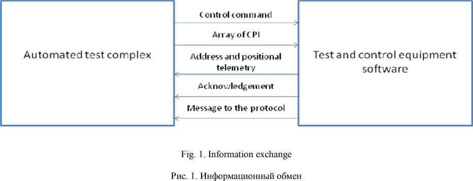
Information exchange is the transfer of data packets of different types between the automated test complex and the software of test and control equipment.
The transport protocol of interaction of the automated test complex and the test and control equipment software of the command and measuring system defines six types of data packets. An automated test system may send the software checkout equipment control commands packages and arrays of command and program information (CPI). Software test and control equipment sends to an automated test system acknowledgement for the used commands, address and positional telemetry, and various messages to the test protocol (fig. 1).
The control command is a data package on which the equipment must perform certain actions. There are three types of commands: commands for test and control equipment, commands for command and measuring system and commands for the control unit of the onboard control complex. The command type determines which hardware the command is addressed to. An array of command and program information is a package containing the necessary data for the control unit of the on-board control complex.
In response to the control command, the test and control equipment software sends an acknowledgement (ACK) to the automated test complex with the information about the execution of the command or with the error code. All error codes are described in the communication information protocol. The ACK is necessary for synchronization of work and prevention of a situation when commands are not identified by the test and control equipment.
Telemetry packets sent to the automated test complex provide information about the values of certain measured parameters that need to be monitored. There are two types of telemetry packets: address and positional. Address telemetry contains the parameters of the test and control equipment, and the positional parameters of onboard systems. At the beginning of the tests, the automated test complex expects a packet of address telemetry with the value of all the parameters of the test and control equipment, then once a second receives a telemetry packet containing only the changed parameters. Positional telemetry packets are transmitted to the automated test complex as they are received from the command and measuring system.
The protocol provides for the possibility of issuing messages to the automated test complex in the test protocol. Such messages are used, for example, to diagnose malfunctions or to comment on the test and control equipment operators.
For the organization of interaction between the automated test complex and the control and test equipment the software subsystem of the organization of carrying out complex tests was created.
Subsystem of organization of carrying out complex tests. The main purpose of the subsystem of the organization of complex tests is to support the interaction between the automated test complex and the test and control equipment of the command and measuring system during complex tests according to the protocols of transport and information interaction. The main functions of the subsystem:
– reception from the automated test complex sent control commands and arrays of command and program information;
– transfer to the automated test complex of the ACK on control commands about their successful performance or with the code of the received error;
– conversion of automated test complex packages into a format acceptable for the command and measuring system and vice versa;
– recording of package exchange between the automated test complex and the command and measuring system in the test protocol;
– implementation of the possibility of entering into the test protocol messages from the test and control equipment operator;
– checking of the tests carried out.
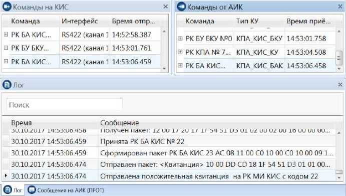
Interface of the complex test subsystem (fig. 2).
The subsystem of complex tests contains the following windows: “Commands to CMS”, “Commands from ATC”, “Log”, “Messages to ATC”, “Parameters of address telemetry”, “Telemetry monitor”.
The “Log” window contains information about the processes that take place during complex tests: receiving commands and arrays of command and software information from the automated test complex, sending acknowledgements, address and position telemetry to the automated test complex, and description of other actions that need to be recorded in the protocol.
Настройки АИК
О Команды на КИС
Обозреватель Свойства Результаты Журнал Монитор Проверка событий телеметрии команд
□
|
Команда |
Интерфейс |
Время отпр... |
|
РК БА КИС... |
RS422 (канал : |
14:59:39.345 |
|
РК БУ БКУ... |
RS422 (канал : |
14:59:41.666 |
|
Массив КПИ |
RS422 (канал ' |
14:59:52.899 |
О Лог
Поиск
Время
27.10.2017 14:59:39.344
27.10.2017 14:59:39.345
27.10.2017 14:59:39.354

|
© © © Редактор базы Редактор Настройки данных сценариев |
Режим АИК |
|
О Команды от АИК |
X |
|
|
Команда Тип КУ * РК KI IA № 4... KI 1А_КИС_КУ |
Время приё... 14:59:30.998 |
|
|
В РК КПА № 5... КПА_КИС_КУ |
14:59:34.968 |
|
|
В РК БА КИС... КПА_КИС_БАК |
14:59:39.339 |
|
|
ж РК БУ БКУ... КПА_КИС_БКУ |
14:59:41.661 |
|
|
ш Массив КПИ МКПИ |
14:59:52.890 |
- |
Сообщение
Принята РК БА КИС № 1
Сформирован пакет РК БА КИС 23 АС 04 11 00 СО 10 00 СО 10 00 09...
Отправлен пакет. <Квитанция> 10 00 35 04 08 8А F8 4Е D3 01 01 00...
27.10.2017 14:59:39.354 Отправлена положительная квитанция на РК МИ КИС с кодом 1
27.10.2017 14:59:41.661 Получен пакет 12 00 D7 05 69 8В F9 4Е D3 01 02 00 03 00 01 00 00 0..
27.10.2017 14:59:41.661 Принята РК БУ БКУ № 1
(^ /Iос ^) Сообщения на АИК (ПРОТ)
|
Параметр ATM |
Знамение |
|
Захват несущей Захват ТМ |
0 - нет (по умолчанию) 0 - нет (по умолчанию) |
|
Адрес дешифратора Идентификатор МАР РК |
0 - Адрес 1 _ умолчанию) 0 - RS232 основной (по умолчанию) |
|
Идентификатор МАР КПИ Выходное напряжение ИБП Загрузка ИБП в процентах |
0 - RS232 основной (по умолчанию) |
|
Температура |
- |
Fig. 2. Interface of the complex test subsystem
Рис. 2. Интерфейс подсистемы проведения комплексных испытаний
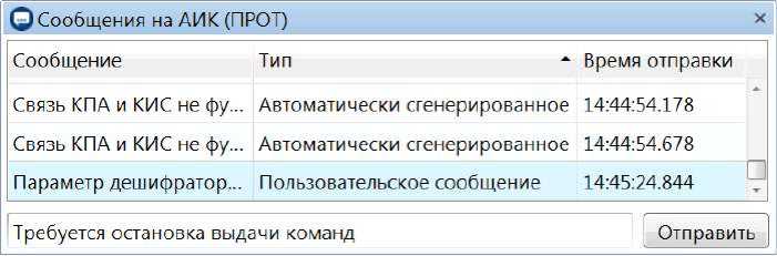
Fig. 3. Messages to the automated testing complex
Рис. 3. Сообщения на автоматизированный испытательный комплекс
“Messages to ATC” window displays messages generated automatically or created by the operator in the process of testing (fig. 3).
“Parameters of address telemetry” window contains the values of test and control equipment parameters. The parameters of the test and control equipment are divided into two types: the parameters of the state of the equipment and the parameters, the value of which determines the various settings of the transmission channel between the test and control equipment and the command and measuring system, as well as between the command and measuring system and other onboard systems of the spacecraft.
The status parameters of the test and control equipment are the values of the sensors of various devices that are part of the test and control equipment, for example, the value of the humidity sensor of the rack control unit or the alarm flag of the first power distributor. Subsystem receives these values through a survey of the equipment in multi-threaded mode using the SNMP protocol [15].
The parameters responsible for the data channels specify certain settings necessary for tests, such as the mode of exchange with the board or the address of the decoder. The value of the parameters of this type is set by commands for test and control equipment, and has a default value. The default value is required to avoid setting of each of the parameters at the beginning of complex tests.
“Telemetry monitor” window displays the telemetry transmitted by the monitored object. The length of the telemetry frame according to the ESA PSS-04-106 standard is 508 bytes. The software allows viewing any telemetry package that needs to be transferred to an automated test complex.
“Commands to CMS”, “Commands from ATC” windows display commands and arrays of control program data transmitted from the automated test complex. The “Commands from ATC” window contains all the packages received from the automated test complex, and clearly displays their structure, provided by the transport interaction protocol. The “Commands to CMS” window displays the packets to be sent to the command and measuring system and displays their structure, provided by the international standard ESA PSS-04-107 (fig. 4).
The structure of the package transferred to the command and measuring system differs from the structure of the package transferred from the automated test complex. To convert the package structure and insert the necessary data, the values of which are contained in the address parameters of the test and control equipment, the subsystem “Data packet editor” is used (fig. 5).
The “Data packet editor” subsystem allows creating a tree-structured packet, consisting of elements that are represented by other structures. An address parameter for each item can defined. The value of this parameter will be inserted into the associated element when the packet is transferred to the object of control. It is also possible to set a default value for each element.
In the data packet editor, structures of all types of data packets were created according to the ESA PSS-04-106 and ESA PSS-04-107 standards and the protocol of transport interaction of the automated test complex and the test and control equipment software. Elements are defined for structures, the value of which must correspond to certain address parameters during the transmission of the packet to the command and measuring system. When a command packet is received, the subsystem identifies the command type.
О Команды на КИС
Команда Интерфейс Время отправки в РК БА КИС № 21 RS422 (канал 1) 16:24:04.832
* РК БА КИС № 21 - 23 АС 04 11 00 СО 10 00 СО 10 00 09 15 04 94 73 33 96
I Заголовок кадра ТК - 23 АС 04 11 00
^ Сегмент ТК - СО 10 00 СО 10 00 09 15 04 94 73
t Заголовок сегмента - СО
* Поле данных сегмента - 10 00 СО 10 00 09 15 04 94 73
Заголовок пакета - 10 00 СО 10 00 09
Поле данных пакета - 15 04
CRC - 94 73
CRC - 33 96
Fig. 4. The structure of the packet transmitted to the command and measuring system
Рис. 4. Структура пакета, передаваемого на командно-измерительную систему
| Поиск
Название
»i 1g Структура пакета РК БУ БКУ
* - ~= Структура пакета РК КИС
%. Выбор режима выдачи Т...
-
* 4? Выбор режима выдачи Т...
‘чд Выбор режима выдачи Т... -
-
• ц* Выбор режима выдачи Т...
^ Выбор режима выдачи Т...
-
1 \1 Выбор режима выдачи Т.~ ^ Включение МКО в основн...
’’jo Включение МКО в резерв...
-
* 4* Включение SpW в основн...
-
* *• Включение SpW в резерв.
-
* Ч« Отключение МКО и SpW в...
^е Отключение МКО и SpW в...
-
* Ч« Switching on the CCU tele ...
-
1 ^е Включение генератора те *4* Выключение генератора т.
-
*45 Выключение генератора т
-
*-.„ Найта«ш»о глшил» г nv
|
| Поиск |
|||||||||
|
Название |
Длина |
Тил поля |
Значение лоумол... |
Контролируемое... |
Тип 3 |
||||
|
• и | Структура пакета РК КИС |
16 |
Байт |
00 00 00 00 00 00 |
00 0 0 00 00 00 00... |
16 |
* |
|||
|
j Заголовок кадра |
5 |
Байт |
00 0 0 00 ОО 00 |
00 00 00 00 00 |
16 |
||||
|
Номер версии |
2 |
Бит |
ОО |
00 |
2 |
||||
|
Флаг обхода и Флаг КУ |
2 |
Бит |
ОО |
00 |
2 |
||||
|
Резервированное поле А |
2 |
Бит |
00 |
00 |
2 |
||||
|
ИД номер КА |
10 |
Бит |
0000000000 |
оооооооооо |
2 |
||||
|
ИД номера виртуального кана . |
6 |
Бит |
оооооо |
СЮ 0030 |
2 |
||||
|
Резервированное поле В |
2 |
Бит |
00 |
00 |
2 |
||||
|
Длина кадра |
1 |
Байт |
00 |
00 |
16 |
||||
|
Номер последовательности ка... |
1 |
Байт |
00 |
00 |
16 |
||||
|
Поле данных кадра (Сегмент ТК) |
9 |
Байт |
00 00 00 00 00 00 |
00 0 0 00 00 00 00... |
16 |
||||
|
0 Заголовок сегмента |
1 |
Байт |
00 |
00 |
16 |
||||
|
Флаги последовательности |
2 |
Бит |
00 |
00 |
2 |
||||
|
Признак МАР |
6 |
Бит |
ОООООО |
оооооо |
2 |
||||
|
1-1 Поле данных сегмента |
8 |
Байт |
00 0 0 00 00 00 ОО |
00 0 0 00 00 0 0 00... |
16 |
▼ |
|||
|
4 |
,11 |
||||||||
Fig. 5. The “Data packet editor” subsystem
|
' Ей Открыть из Сохранить о файла... • файл... ’ |
"о " © о т/ Создать Удалить Создать Редактировать структуру структуру поте попе |
Создать пакет Импорт данных |
|
Управление |
Структура длинах |
Пакеты данных |
Рис. 5. Подсистема «Редактор пакетов данных»
Источник питания 27 В-
Старт стоп
Воспроизведение результатов
14:52:41.1
30.10.2017
Открыть
Источник питания
100 в-

Сформировать
14:53:08.1
Параметр А...
Количество
Количество попыток закладки очередной
Режим обмена с бортом
Номер успешно заложенной фразы КПИ в КИС принятых от АИК фраз КПИ
Управление панелями АИК-
14:53:174
30.10.2017
ОI араметры адресной те... х
Значение
в -Технологиче Е ский канал
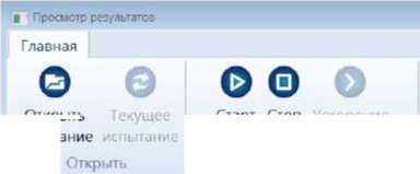
Fig. 6. Reproduction of passed tests
Рис. 6. Воспроизведение пройденных испытаний
If a command needs to be sent to the command and measuring system, the subsystem determines the list of address parameters required to configure the command. Then there is the formation of a command packet to be sent to the command and measuring system and the insertion of address parameters in the corresponding fields of the generated packet. After that, the received packet is sent to the test and control equipment for further sending to the command and measuring system.
After conducting complex tests, it is necessary to be able to analyze them. For this purpose the problem of preservation of tests and realization of functions of reproduction of earlier carried out tests was solved. Reproduction of passed tests is shown in fig. 6.
Visualization of the tests is performed using a timeline. Using the timeline, you can reproduce complex tests from any point in time in real-time or accelerated mode, showing all actions that have occurred by that moment.
Conclusion. The developed subsystem is implemented in the software and hardware complex of test and control equipment of the command and measuring system and provides support for the application of the command and measuring system in complex tests of the spacecraft. The subsystem interacts with the automated test complex according to the protocols of transport and information interaction. The subsystem receives commands and executes them if they belong to the test and control equipment or transfers them to the object of control, having previously converted them into a clear command and measuring system structure. For each command, the subsystem sends an acknowledgement of correct identification, or with an error code according to the information exchange protocol.
The subsystem receives telemetry from the command and measuring system, converts it according to the transport interaction protocol and sends it to the automated test complex. In addition to the telemetry of the object of control, the subsystem sends to the automated test complex telemetry of test and control equipment, which contains the parameters of sensors of various equipment of control and testing equipment, as well as the parameters necessary to config ure the transmission channel between the test and control equipment and the command and measuring system or between the command and measuring system and other systems of the spacecraft.
All the process of complex tests is recorded in the test protocol. The subsystem has the ability to record messages from the operator of test and control equipment. All tests are saved and it is possible to reproduce them for analysis. The subsystem solves the task of the interaction of automated test complex and test and control equipment for complex tests of command-measuring system of the spacecraft.
References Organization of complex testing of the spacecraft command and measuring system
- Соловьёв В. А. Управление космическими полетами // Земля и Вселенная. 2013. №. 6. С. 3-14.
- Александровская Л. Н., Круглов В. И., Кузнецов А. Г. Теоретические основы испытаний и экспериментальная отработка сложных технических систем. М.: Логос, 2003. 736 с.
- ГОСТ Р 53802-2010. Системы и комплексы космические. Термины и определения. М.: Стандартинформ, 2011. 28 с.
- Saleh J. H., Lamassoure E., Hastings D. E. Space systems flexibility provided by on-orbit servicing. Pt. 1 // Journal of Spacecraft and Rockets. 2002. Vol. 39, No. 4. P. 551-560.
- ГОСТ Р 54317-2011. Комплексы стартовые и технические ракетно-космических комплексов. Требования безопасности. М.: Стандартинформ, 2011. 28 c.
