Особенности механизма формирования нагрузки на систему "крепь-межрамное ограждение"
Автор: Петренко Ю.А., Касьян Н.Н., Касьяненко А.Л.
Журнал: Горные науки и технологии @gornye-nauki-tekhnologii
Рубрика: Свойства горных пород. Геомеханика и геофизика
Статья в выпуске: 3, 2019 года.
Бесплатный доступ
Исследованы особенности формирования нагрузки на систему «крепь - межрамное ограждение» в процессе формирования вокруг выработки зоны разрушенных пород путем лабораторных исследований на моделях из эквивалентных материалов и структурных моделях. Выявлена роль межрамного ограждения при формировании нагрузки на рамные крепи. Установлено, что над межрамными ограждениями внутри зоны разрушенных пород образуется свод естественного равновесия, который перераспределяет нагрузку на рамы крепи, а на межрамные ограждения оказывает давление вес пород внутри этого свода. Разработаны требования к межрамным ограждениям рамных крепей горных выработок.
Межрамные ограждения, затяжка, жесткость, рамная крепь, нагрузка на крепь, горное давление, эквивалентные материалы, структурные модели
Короткий адрес: https://sciup.org/140246554
IDR: 140246554 | DOI: 10.17073/2500-0632-2019-3-202-212
Текст научной статьи Особенности механизма формирования нагрузки на систему "крепь-межрамное ограждение"
Challenge problem. With increasing depth of mining, supporting of operating mine workings became one of the most pressing problems. Attempts to ensure maintenance-free supporting the workings at the expense of increasing load-bearing capacity of the support failed. At present, specific volume of mine support resetting in the Donbass mines has reached 7.5 m per 1,000 tons of production, and the labor inputs to repair and maintain the mine workings are 565.2 person-shift per 1 km of supported workings per year, or about 50 person-shift per 1,000 tons of production. The cost of the support re-setting per one meter of production is up to 50-60% of the initial support cost. The state of mine workings in the Donbass mines is
National University of Science and Technology characterized by the following figures: about of 50% of the mine workings have been deformed, including for the horizontal development workings – 64 %, for the inclined workings – 52 %, and for the shaft bottom workings – 43 %. Of the total volume of the deformed workings, 20 % are in emergency condition, and this leads not only to increasing the costs of maintaining workings, but also significantly affects the mining safety.
That is why improvement of the mine working support design on the basis of revealing features of the mechanism of originating load on them is an urgent task.
Findings of reviewing recent studies and publications. The mechanism of interaction between frame support of the workings and the surrounding rock mass is very complicated and ambiguous. The existing idea that the support bearing reaction is distributed along the inner surface of the working to a width equal to the support setting increment does not reflect the actually observed situation in mine conditions, especially in case of formation of broken (fractured) rock zone. In practice, the support bearing reaction takes place within the surface of contact between them only. In interframe space, magnitude of the support bearing reaction to the rock mass is determined by the support setting increment and the interframe shield rigidity. In this case, only the supporting frames are the supporting element resisting unstable rocks.
The nature of the load distribution along the perimeter of the frame support has been thoroughly studied to date [1–7]. At the same time, the support is a spatial structure, and the question of the mechanism of the frame support interaction with the host rock mass, taking into account the rock deformation features in the interframe space, has not yet been fully studied. Most researchers define lagging (interframe shield) as a support element designated to protect a mine working from rock falls in the spaces between the support frames [8–16]. At the same time, the results of mine working surveys show that the lagging state is much worse than the condition of the support frames themselves [17–20]. Therefore, in recent years, more attention has been paid to the lagging load-carrying function, which consists in receiving pressure from the rock mass and transferring it to the support frames [21–25]. At the same time, most of the developed mine laggings are rigid structures, bearing capacity of which is close to bearing capacity of the frame sets. This leads to increasing material consumption and the complexity of working support setting. This approach to solving the problem of interframe shields does not reflect the actual mechanism of the adjustable lagging frame support operation.
Study objective. To reveal the features of originating load on "support-interframe shield" system in the process of formation of broken rock zone around a mine working, taking into account the interaction of the support frames with the rock mass.
Research Findings. To achieve this goal, we used the method of physical modeling using models made of equivalent materials and structural models. The investigation was carried out in several stages.
-
1. To reveal the influence of lagging operating mode (rigid or adjustable lagging) and the support frame spacing on the magnitude and nature of the support frame loading.
-
2. To reveal the features of the mechanism of the support frame and lagging loading at adjustable lagging mode.
-
3. To substantiate the requirements for adjustable lagging parameters.
The model was loaded using pneumocylinders. As the equivalent materials, gypsum-sand mixtures were used in the modeling.
National University of Science and Technology
When developing structural models, marble chips with particle size of up to 10 mm were used as the material for the models.
A layered rock mass having uniaxial compression strength of 40–60 MPa was modeled. In the models, the roof support frames along the working length were installed in increments of 60; 40; 20 and 13 mm, which correspond to 1.5; 1.0; 0.5; and 0.33 m in field (mine) conditions. To study the stress distribution in the rock mass, in the models, friction sensors were installed tightly at a distance of 30 and 70 mm from the working contour. Similar sensors were installed under the roof support frames.
The arrangement of the sensors is shown in Fig. 1. Before testing the models, the readings of the sensors were recorded with no external load. Then, in the process of testing the models, the sensor readings were recorded when the magnitude of the external load changed.
At first, model No. 1 with rigid lagging was tested. The results of measuring pressure on the roof support frames and stresses in the surrounding rock mass are presented in Figures 2, 3. Analysis of the results of measuring pressure on the roof support frames (see Fig. 2) shows that decreasing spacing between the support frames results in decreasing the load on each frame. In this case, the readings of the sensors under frames No. 1 and 12 were not taken into account, since they were located close to the model body.
For instance, decreasing the frame spacing from 1.5 to 0.33 m decreases the load on the frame from 121 to 42 kPa. This confirms correctness of the existing opinion that the role of rigid lagging in the formation of the support load is confined only to the load redistribution on the frames, depending on their spacing.
Analysis of the graphs of pressure distribution in the model mass (see Fig. 3) shows that it also depends on the support frame spacing. For instance, with the frame spacing of 1.5-0.5 m, directly above the frames, pressure maximum is observed, while with decreasing the frame support spacing, the difference between the pressure above the support frames and between them decreases. At the frame spacing less than 0.5 m, the pressure in the rock mass is more evenly distributed. The same pattern is observed at greater distance from the working contour.
26 29 31 32 34
2nd layer sensors
1st layer sensors
Roof support frames
Sensors installed under the roof support frames
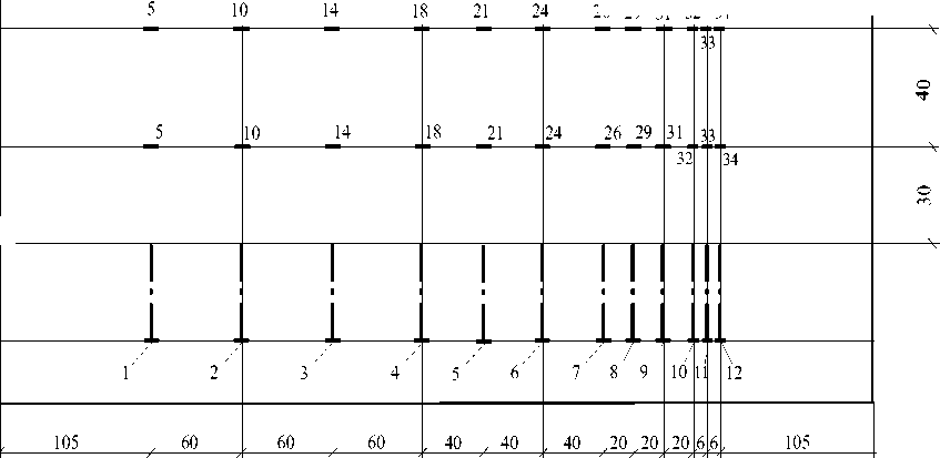
Fig. 1. Layout of pressure sensors in the model
National University of Science and Technology
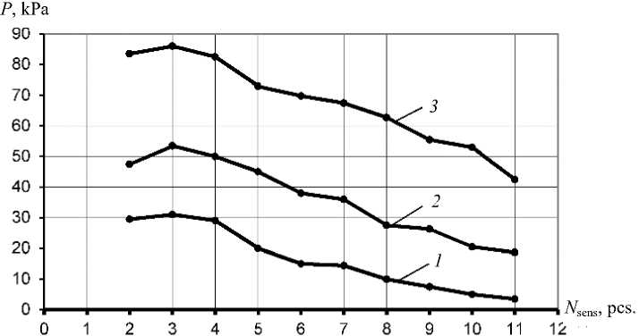
Fig. 2. Results of measuring pressure on support frames ( P ) with rigid lagging at external load of 0 kPa ( 1 ), 20 kPa ( 2 ) and 40 kPa ( 3 )
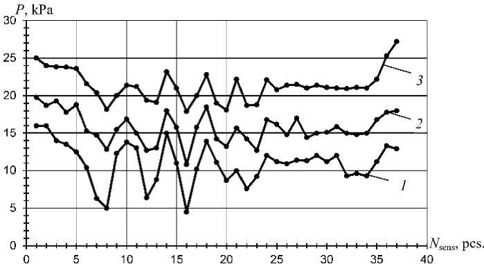
Fig. 3. Results of measuring pressure on the first layer sensors in the model with rigid lagging at external load of 0 kPa ( 1 ), 20 kPa ( 2 ) and 40 kPa ( 3 )
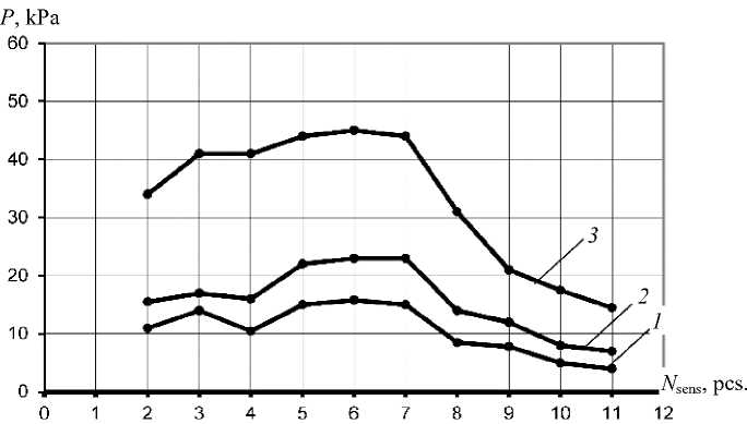
Fig. 4. Results of measuring pressure on support frames ( P ) with adjustable lagging at external load of 0 kPa ( 1 ), 20 kPa ( 2 ) and 40 kPa ( 3 )
ГОРНЫЕ НАУКИ И ТЕХНОЛОГИИ
National University of Science and Technology
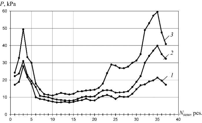
Fig. 5. Results of measuring pressure on the first layer sensors in the model with adjustable lagging at external load of 0 kPa ( 1 ), 20 kPa ( 2 ) and 40 kPa ( 3 )
Obviously, the support frames act as pressure concentrators, since their bearing capacity and rigidity are much greater than that of the lagging. As a result, the rock mass immediately above the frames is broken to a greater extent. With the frame spacing of less than 0.5 m, the bearing capacity and rigidity of the support along the working length do not practically change and the pressure is distributed more evenly along the working length. Consequently, increasing the lagging rigidity will lead to more intense breakage of the rocks between the frames.
Model No. 2 was tested in similar conditions, but with the adjustable lagging. The results of measuring pressure on the roof support frames and stresses in the surrounding rock mass are presented in Figures 4, 5. As can be seen from the above data, the support frames load, at with the frame spacing from 0.5 m to 1.5 m is distributed evenly and practically does not depend on the distance between the frames. At the frame spacing of 0.5 m or less, the support frames load is distributed in the same way as with the rigid lagging, i.e. as the distance between the frames decreases, the load decreases too.
The pressure distribution in the rock mass is uniform at the frame spacing of 0.5–1.5 m, while the pressure concentration above the support frames is not observed. With the frame spacing of less than 0.5 m, the pressure in the rock mass is distributed in the same way as with the rigid lagging.
The performed studies allow to conclude that with the support frame spacing of more than 0.5 m, the lagging not only protects the working from possible collapses, but also participates in the process of forming the load on the support frames. Moreover, the greater the lagging adjustability, the more evenly the pressure is distributed on the frames and in the rock mass along the working length.
At the support frame spacing of less than 0.5 m, the role of lagging is confined to supporting backfilling material only;
For more detailed studying the mechanism of forming the load on the roof support frames, models Nos. 3, 4, 5 were tested. To model the
National University of Science and Technology zone of broken rocks (ZBR), marble chips with particle size of up to 10 mm were used as the model material. In the model, the support frames along the working length were installed with spacing of 40 mm that corresponded to the support frame spacing of 1.0 m in the field (mine) conditions. The friction sensor was installed under each support frame. Adjustable lagging was installed between the frames 1–4, whereas the rigid one, between the frames 4–7. In models Nos. 3, 4, and 5, the size of the broken rock zone above the working was simulated, being equal to half the frame spacing, the frame spacing, and the doubled frame spacing, respectively.
The results of measuring pressure on the roof support frames in models 3, 4, and 5 are presented in Figs. 6, 7, respectively.
The analysis of the obtained data showed that at the initial stage of the the broken rock zone formation (at the external load of 0–10 kPa), the lagging adjustability does not produce significant effect on the support load.
Starting with the external load of 10 kPa, the load on frames with adjustable lagging grows less intensively and is 1.5–2.5 times less than that on the frames with rigid lagging. With increasing the external load above 30 kPa, the intensity of loading the frames with adjustable lagging increases, whereas in case of the rigid one the intensity decreases. But on the whole, the load on the frames with adjustable lagging, as established earlier, is 30–40 % less than that on the frames with rigid lagging.
Such mechanism for forming support frame load can be explained as follows. Beginning with the external load of 10 kPa, the adjustable lagging deflects and, when the broken rock zone size exceeds half of the frame spacing, the natural self-supporting arch is formed over interframe shields between the frames. The arch is completely formed at the external load of 30 kPa (Fig. 8). After this, the support frame load begins to increase more intensively with increasing the external load.
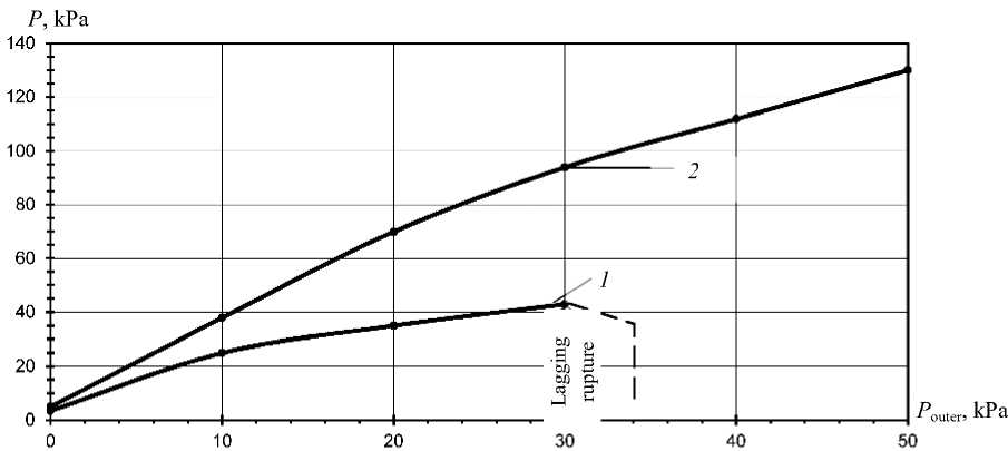
Fig. 6. Results of measuring pressure on support frames ( P ) in model No. 3 depending on external load ( P ext ):
1 – with adjustable lagging; 2 – with rigid lagging
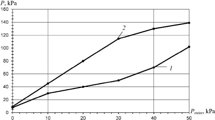
Fig. 7. Results of measuring pressure on support frames ( P ) in models Nos. 4, 5 depending on external load ( P ext ) :
1 – with adjustable lagging; 2 – with rigid lagging
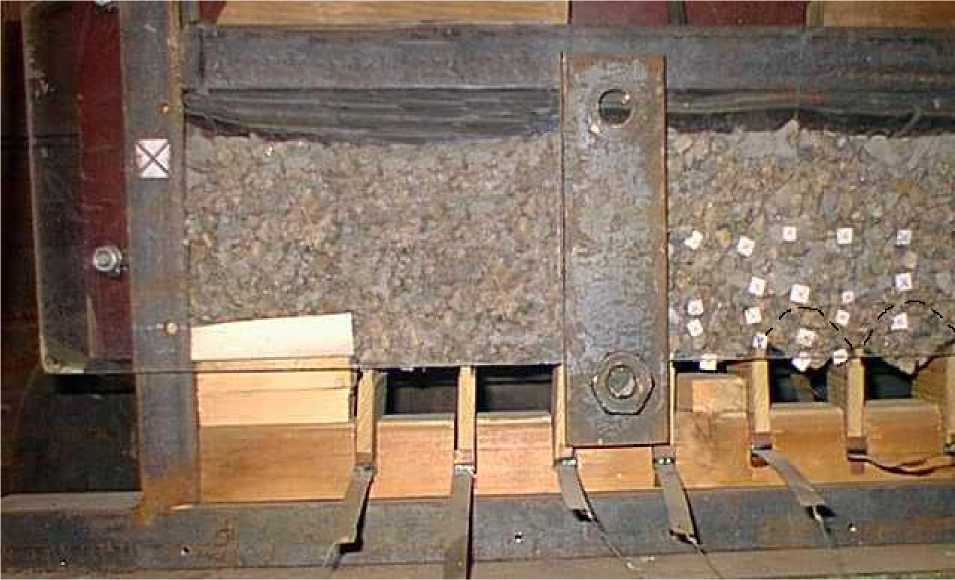
Fig. 8. Behavior of model with rigid and adjustable lagging
The load on the frames with rigid lagging increases almost linearly with increasing the external load, since the lagging only redistributes the load on the frames. However, at the external load of more than 30 kPa, the lagging deflects and receives a part of the working contour displacements and thereby reduces the frame load. After formation of natural self-supporting arches in the interframe space, the lagging bears the load from the weight of rock within this arch only. And since these arches bear on the support frames, at further growth of the broken rock zone around the working, the load is redistributed only to the support frames and not transmitted to the lagging.
ГОРНЫЕ НАУКИ И ТЕХНОЛОГИИ
National University of Science and Technology
The performed studies allow to clarify the mechanism of originating load on "support-interframe shield" system in the process of formation of broken rock zone around a mine working, which consists in the following:
In the initial period of broken rock zone formation around the working (the zone size does not exceed the frame spacing), and in absence of the lagging deformation, the latter only redistributes the load caused by the working contour displacements to the support frames, with no significant effect on the load magnitude. With further expanding the zone into the rock mass and the lagging deflection due to rock displacements into the working space, since its rigidity and bearing capacity are less than those of the support frame, natural self-supporting arches begin to originate between the frames along the working longitudinal axis.
Formation of the natural self-supporting arch between the support frames along the working allows to explain the fact that in mine conditions, even at significant deformations of adjustable support with reinforced concrete lagging, complete failure of the lagging and collapse of the rocks between the support frames is not observed. At the same time, the lagging loadbearing capacity is much less than that of the support frame.
The revealed mechanism allows to formulate requirements for the interframe shield parameters:
-
- the lagging adjustability should provide the opportunity of originating natural selfsupporting arches within the broken rock zone in the interframe space with no rupture (collapse) of the zone;
-
- the lagging load-bearing capacity should provide bearing the load from the weight of the rocks within the natural self-supporting arch.
Conclusions and direction of further research. Summarizing the results of the studies, the following can be noted:
-
- lagging, both rigid and adjustable, is involved in the process of forming the support load at the support frame spacing of 0.5 m or more. At the support frame spacing of less than 0.5 m, the role of lagging is confined to supporting backfilling material only;
-
- with rigid lagging, the support frame load decreases with decreasing the frame spacing, i.e. rigid lagging only redistributes the surrounding rock mass load on the support frames. At the same time, pressure concentration and more intense rupture of the rock mass are observed above the frames;
-
- with adjustable lagging, the support frame load at the frame spacing of more than 0.5 m and the pressure in the rock mass are evenly distributed and do not significantly depend on the distance between the frames. With the support frame spacing less than 0.5 m, the frame load and are distributed in the same way as with the rigid lagging;
-
- with adjustable lagging, as the zone of ruptured rocks around the working expands into the rock mass and the lagging deflection takes place, a natural self-supporting arch is formed over interframe shields (between the support frames) within the broken rock zone. In this case, after the natural self-supporting arch formation completion, the roof support frame load increases more intensively with increasing the external pressure;
-
- with adjustable lagging and the support frame spacing of more than 0.5 m, the frame load is 30-40% less than that with rigid lagging.
The objective of further research is to develop the methodology for calculating the interframe shield parameters.
ГОРНЫЕ НАУКИ И ТЕХНОЛОГИИ
National University of Science and Technology
ГОРНЫЕ НАУКИ И ТЕХНОЛОГИИ
National University of Science and Technology
ГОРНЫЕ НАУКИ И ТЕХНОЛОГИИ
National University of Science and Technology
Горный информационно-аналитический бюллетень (научно-технический журнал). 2012. Отд. вып. № 7. С. 34–43.
Список литературы Особенности механизма формирования нагрузки на систему "крепь-межрамное ограждение"
- Литвинский Г. Г. Закономерности формирования нагрузки на крепи горных выработок // Сб. науч. тр. ДонГТУ. 2016. № 3 (46). С. 5-15.
- Петренко Ю. А., Новиков А. О., Подкопаев С. В., Александров С. Н. Об особенностях формирования нагрузки на крепь выработок глубоких шахт. Физико-технические проблемы горного производства. 2011. Вып. 14. С. 133-141.
- Li C. Rock support design based on the concept of pressure arch // International Journal of Rock Mechanics and Mining Sciences. 2006. Vol. 43(7). Pp. 1083-1090. DOI: 10.1016/j.ijrmms.2006.02.007
- Дрибан В. А., Новиков А. О. О механизме потери устойчивости горных выработок и способах управления состоянием вмещающего их массива // Науковi працi УкрНДМI НАН України. 2012. № 11. С. 275-292.
- Kong X., Liu Q., Pan Y., Liu J. Stress redistribution and formation of the pressure arch above underground excavation in rock mass // European Journal of Environmental and Civil Engineering. 2017. DOI: 10.1080/19648189.2018.1541824
- Huang X., Zhang Z. Stress arch bunch and its formation mechanism in blocky stratified rock masses. Journal of Rock Mechanics and Geotechnical Engineering. 2012. Vol. 4. No. 1. Pp. 19-27.
- DOI: 10.3724/SP.J.1235.2012.00019
- Касьян Н. Н., Новиков А. О., Петренко Ю. А., Шестопалов И. Н., Резник А. В. Металлическая податливая крепь. Патент Украина, № a201102997, 2013.
- Скобенко А. В., Хозяйкина Н. В., Дерыш В. В. Совершенствование рамной крепи протяженных выработок угольных шахт. Днепропетровск: НГУ, 2014. 96 с.
- Lisjak A., Grasselli G. A review of discrete modeling techniques for fracturing processes in discontinuous rock masses. Journal of Rock Mechanics and Geotechnical Engineering. 2014. Vol. 6. No. 4. Pp. 301-314.
- DOI: 10.1016/j.jrmge.2013.12.007
- Мещанинов С. К. Методы моделирования и управления надежностью функционирования горных выработок. Днепропетровск: НГУ, 2011. 360 с.
- Alshkane Y. M., Marshall A. M., Stace L. R. Prediction of strength and deformability of an interlocked blocky rock mass using UDEC // Journal of Rock Mechanics and Geotechnical Engineering. 2017. Vol. 9. No. 3. Pp. 531- 42.
- DOI: 10.1016/j.jrmge.2017.01.002
- Bidgoli M. N., Zhao Z., Jing L. Numerical evaluation of strength and deformability of fractured rocks. Journal of Rock Mechanics and Geotechnical Engineering. 2013. Vol. 5. No. 6. Pp. 419-430.
- DOI: 10.1016/j.jrmge.2013.09.002
- Kazerani T. Effect of micromechanical parameters of microstructure on compressive and tensile failure process of rock // International Journal of Rock Mechanics and Mining Sciences. 2013 Vol. 64. Pp. 44-55.
- DOI: 10.1016/j.ijrmms.2013.08.016
- Khani A., Baghbanan A., Norouzi S., Hashemolhosseini H. Effects of fracture geometry and stress on the strength of a fractured rock mass // International Journal of Rock Mechanics and Mining Sciences. 2013. Vol. 60. Pp. 345-352.
- DOI: 10.1016/j.ijrmms.2013.01.011
- Wang X., Zhao Y., Lin X. Determination of mechanical parameters for jointed rock masses. Journal of Rock Mechanics and Geotechnical Engineering. 2011. Vol. 3, sup. 1. Pp. 398-406.
- DOI: 10.3724/SP.J.1235.2011.00398
- Макшанкин Д. Н. Обоснование крепления горных выработок металлической крепью из шахтного профиля. Автореф. дис. … канд. техн. наук. Кемерово, 2012. 19 с.
- Демин В. Ф., Демина Т. В., Алиев С. Б., Разумняк Н. Л. Исследование проявлений горного давления и характера взаимодействия различных видов крепления с вмещающими породами вокруг выработки. Горный информационно-аналитический бюллетень (научно-технический журнал). 2012. Отд. вып. № 7. С. 34-43.
- Zhang L. Evaluation of rock mass deformability using empirical methods // Underground Space. 2017. Vol. 2. No. 1. Pp. 1-15.
- DOI: 10.1016/j.undsp.2017.03.003
- Литвинский Г. Г., Смекалин Е. С. Эффективность рамных конструкций крепи // Сб. науч. тр. ДонГТУ. 2015. № 1 (44). С.18-25.
- Кошелев К. В., Петренко Ю. А., Новиков А. О. Охрана и ремонт горных выработок. М.: Недра, 1990. 218 с.
- Петренко Ю. А. Геомеханические основы сохранения устойчивости выработок глубоких шахт на различных этапах их эксплуатации. Автореф. дис. … д-ра техн. наук. Донецк, 2008. 30 с.
- Bidgoli M. N., Jing L. Anisotropy of strength and deformability of fractured rocks // Journal of Rock Mechanics and Geotechnical Engineering. 2014. Vol. 6. No. 2. Pp. 156-164.
- DOI: 10.1016/j.jrmge.2014.01.009
- Saeidi O., Rasouli V., Vaneghi R.G., Gholami R., Torabi S.R. A modified failure criterion for transversely isotropic rocks // Geoscience Frontiers. 2013. Vol. 5. No. 2. Pp. 215-225.
- DOI: 10.1016/j.gsf.2013.05.005
- Ciz R., Siggins A.F., Gurevich B., Dvorkin J. Influence of microheterogeneity on effective stress law for elastic properties of rocks // Geophysics. 2008. Vol. 73 (1). Pp. E7-E14.
- DOI: 10.1190/1.2816667
- Li Q., Shi W., Yang R. Deformation mechanisms in a coal mine roadway in extremely swelling soft rock // SpringerPlus. 2016. Vol. 5(1). 1310.
- DOI: 10.1186/s40064-016-2942-6

