Overview and Comparison of Candidate 5G Waveforms: FBMC, UFMC and F-OFDM

Author: Ali J. Ramadhan
Journal: International Journal of Computer Network and Information Security @ijcnis
Article in issue: 2 vol.14, 2022.
Free access
The fifth generation (5G) technology standard, utilizing the Internet of Things, promises enhanced communication systems. However, the efficiency expected from such systems entails significant requirements, such as higher data rates and flexibility of the lowest 5G layer. Meeting these requirements in subsequent wireless communication systems is highly dependent on the use of waveforms capable of efficiently enabling multiple access. In other words, proper waveforms determine the effective handling of diverse traffic within a given band. In this study, four candidate multicarrier waveforms, namely filtered orthogonal frequency division multiplexing, filter bank multicarrier, universal filtered multicarrier, and orthogonal frequency division multiplexing, which is currently used in 4G systems, are compared based on multiple parameters. MATLAB simulation results indicate that the waveforms significantly improved spectrum localization and provided appropriate spectrum fragmentation. As these waveforms can mix diverse traffic specifications, they handle the problem of time-frequency synchronization effectively. Therefore, these new waveforms exhibit significant potential in terms of orthogonality and synchronicity and can support numerous users without dropping signals. In addition, they support all applications and scenarios related to multiple-input and multiple-output. The obtained simulation results confirm the suitability of such waveforms for 5G applications and systems.
4G, 5G, orthogonal frequency division multiplexing (OFDM), filter bank multicarrier (FBMC), universal filtered multicarrier (UFMC), filtered OFDM (F-OFDM)
Short address: https://sciup.org/15018266
IDR: 15018266 | DOI: 10.5815/ijcnis.2022.02.03
Text of the scientific article Overview and Comparison of Candidate 5G Waveforms: FBMC, UFMC and F-OFDM
Published Online April 2022 in MECS DOI: 10.5815/ijcnis.2022.02.03
By design, fourth generation (4G) long term evolution (LTE) systems rely on the orthogonal frequency division multiplexing (OFDM) technique utilized in multicarrier systems to improve spectrum efficiency and address the frequency selective problem. The OFDM technique uses the cyclic prefix (CP) to protect symbols, and the modulation is based on the inverse fast Fourier transform (IFFT).
In 2010, the 4G LTE standard advanced in the domain of wireless digital communication to provide novel wireless broadband data services globally [1]. A decade later, driven by the emergence of a new generation of radio systems with higher specifications and requirements, LTE has been considered an outdated system incapable of meeting the current requirements of massive data rates.
Therefore, novel multicarrier techniques have been introduced to address the shortcomings of the existing techniques. Filtered OFDM (F-OFDM) and universal filtered multicarrier (UFMC) techniques are considered as the prime candidates owing to certain advantages. Whereas UFMS applies the filtering process to each sub-band, the filtration in UFMC is applied to the entire band. Additionally, a sinc filter shapes the subcarriers in the frequency domain, wherein the subcarriers are sufficiently flexible to appropriately suit any filter design with lowered levels of the side lobe. In fifth generation (5G) systems, Internet of Things (IoT) devices serve as the nodes of a network, and the transported bursts vary based on numerous factors such as the number of devices, response time, packet size, frequency, and other characteristics of each device. Therefore, 5G is capable of meeting diverse requirements, such as tolerance in the case of time-frequency misalignment and emission accompanied by lowered out of band (OOB) [2].
The European Union Mobile and Wireless Communications Enablers for the 2020 Information Society (METIS 2020) project aims to increase the volume of mobile data by 1000 times per area, increase the battery life of massive machine communication by a factor of 10, increase the number of connected devices and user data rates from 10 to 100, and decrease end-to-end latency by 5 times compared with those of the existing devices. Multiple factors must be combined to achieve these goals. For example, the current spectrum must be utilized more efficiently, a new spectrum of 6 GHz must be available for service, the generalization of small cells must be considered, and a novel massive multiple-input and multiple-output (MIMO) air interface must be introduced [3].
Although 4G systems rely on OFDM modulation, the lack of flexibility in waveforms and unsatisfactory confinement of the spectrum are the two major defects that render OFDM modulation unfit for 5G and the multiple services it offers. To use the current bandwidths at -6 GHz in the most optimal manner, dynamic spectrum aggregation is essential. Additionally, high emission occurs in the OOB when using OFDM, and the data rates of communication services are lowered because of single subcarrier allocation resulting from resource block granularity. In the case of high-mobility applications, other problems emerge with frequency shifts owing to Doppler effects. The reduction of latency in OFDM and the use of CP to handle interference decreases the efficiency of the spectrum. Therefore, a new system relying on suitable flexibility of the waveform to successfully encounter the challenging requirements presented by the physical layer of 5G must be developed [4].
In this study, OFDM, UFMC, F-OFDM, and filter bank multicarrier (FBMC) are compared in terms of error probability as competing waveforms while varying certain parameters.
The remainder of this study is organized as follows. Section 2 describes the related research. Section 3 introduces the four competing waveforms, and Section 4 presents the block diagrams representing these systems. Section 5 presents time-frequency and other comparison metrics, and subsequent sections use extensive trace-driven simulation to investigate the system. The final section concludes the work and highlights some suggestions for further research.
-
2. Related Research
In 2019, Demir et al. [5] explored major requirements, such as high energy efficiency, low latency, asynchronous transmission, and spectrum efficiency, that waveforms must fulfill to identify and demonstrate the basic indicators of 5G performance, namely enhanced mobile broadband (eMBB), ultra-reliable and low latency communications (URLLC), and massive machine-type communications (mMTC). In addition, the study presented potential waveforms compatible with 5G and analyzed their weaknesses and strengths.
Stasio et al. [6] identified the developed services and related requirements of 5G and discussed the efficiency of OFDM as introduced by the Third Generation Partnership Project (3GPP) in meeting such requirements. This study highlighted how optimized spectral localization and reduced OOB emissions can be obtained using F-OFDM and windowing OFDM (W-OFDM). Moreover, the authors discussed the merits and demerits of diverse schemes while presenting the diagrams of the transmitter block and numerical results of experiments.
Additionally, 5G technology was examined to explain the novel multiple service schemes and optimize the spectral efficiency using the most convenient radio resources available [7]. The authors tabulated the parameter values of a simulation and presented diagrams analyzing the waveforms.
Banelli et al. [8] identified the most suitable multicarrier modulation for 5G. They analyzed the strengths and weaknesses of the commonly used OFDM and evaluated the waveforms that might improve its performance. The authors used receiver and transmitter constraints to measure waveforms with numerical examples. The study evaluated the spectral efficiency, peak-to-average power ratio (PAPR), and power spectral density (PSD) of the UFMC and FBMC schemes.
Recently, the benefits of using the UFMC and FBMC schemes in 5G were explained and examined [9]. The study concluded that withholding OOB leakage and migrating PAPR can improve the waveforms.
Furthermore, the defects of the CP used in frequency division multiplexing (CP-OFDM) waveforms were disclosed based on its comparison with UFMC [10], including reduced spectrum efficiency and OOB emissions. The authors measured UFMC performance using MATLAB, and certain advantages, such as the reduction in the OOB emission by 40 dB, were established in comparison with the results of CP-OFDM.
Another study considered UFMC to be better than CP-OFDM [11] as inter-carrier interference and sidelobes are reduced. This is because UFMC is a nonorthogonal waveform, using narrowed filtering on sperate groups of subcarriers rather than treating them as a whole.
Additionally, OFDM was compared with UFMC by analyzing and describing the structure of the associated transmitters and receivers [12]. Furthermore, FBMC modulation was determined as the most suitable technique to meet the challenging requirements of 5G [13]. The authors utilized the transmitter and receiver to prove that FBMC performance is better than that of OFDM. They analyzed the differences in packet delivery ratio, signal-to-noise ratio, and bit error rate (BER) of the two waveforms before discussing the advantages and disadvantages of FBMC.
The aforementioned studies on 5G require advanced knowledge to adequately understand the new waveforms, and are thus considered slightly complex for novice researchers in the field. Therefore, the present work provides theoretical knowledge and presents the fundamental details of OFDM to clarify the F-OFDM, UFMC, and FBMC waveforms. Additionally, it summarizes useful information on the earlier mobile generations to understand the factors influencing 5G. Moreover, this study offers complete adaptability of the included simulation code.
-
3. Theoretical Overview
-
3.1. OFDM
This section discusses all the available waveforms for 5G. It briefly introduces OFDM, considered as a modulation reference, along with the newly developed F-OFDM and UFMC. In addition, both FBMC and filtered multi-tone are outlined as less-matured variants of OFDM.
OFDM is an uncomplicated technique of multicarrier modulation utilized in numerous applications. In contrast to the data in single carrier modulations, which can fill the entire bandwidth, the data in multicarrier modulation are transmitted using orthogonally flat and narrow subcarriers with a separate bandwidth within the channel’s main bandwidth. Thus, a flat fading channel is generated at each subcarrier. To improve the flatness of the channel at each subcarrier and ensure orthogonality, an identical copy of the last part of a sample (CP) is placed at the end of each symbol, where Lcp represents its length.
The major advantage of OFDM is the parallel production of data streams using overlapping subcarriers, proving its efficiency over the traditional technique generally used in bandwidths. The subcarriers are orthogonal owing to the fast Fourier transform (FFT), which avoids interference. Flat fading can be achieved in OFDM by producing low-rate data streams against subcarriers [14].
OFDM transmission occurs in a symbol-by-symbol manner. Therefore, when K = 1 and k ∈ [-Lcp, M - 1], the OFDM baseband symbol is expressed as j 2nmk
E M -1 —77—
cme m = 0
where c m represents the transmitted complex symbols at one subcarrier m , similar to quadrature amplitude modulation (QAM) constellations. FFT and IFFT can realize this operation.
Despite the time-dispersive nature of the channel, orthogonality is maintained in OFDM because the receiver uses a simple method to equalize and estimate the channel. However, OFDM has several deficiencies owing to the rectangular pulse used; therefore, Fourier transform is the implicit solution for pulse shaping.
-
3.2. FBMC
FBMC introduces structured transmission using a pulse shape better than that of OFDM at Nyquist rate while maintaining orthogonality. In addition, the requirements of the Balian–Low theorem can be avoided in FBMC [15].
Compared with the OFDM technique, wherein complex symbols are transmitted at subcarriers, FBMC transmits imaginary and real portions of complex symbols separately in isolation with a time delay equaling half a symbol, T /2. For any integer k , the FBMC baseband signal is given as follows:
j 2 n mk
E ^ i M —1
n e Z L m =0 a m,n
g( k — nN 1) e M ej 0 m ’ n
g m , n ( k )
where g is the filter; N 1 = M /2 is the offset of the discrete-time signal; φ m , n is an additional phase term at subcarrier m and symbol index n , expressed as π/2( n + m ); and am,n is the real value of the transmitted symbols obtained using the real and imaginary parts of a QAM constellation. For perfect reconstruction, filter g must satisfy the orthogonality condition
R { Lke g m , n ( k ). g p , q ( k ) } = 5 m , P 5 " , q
where ∗ is the complex conjugation, δ m,p = 1 if m = p , and δ m,p = 0 if m ≠ p .
Similar to OFDM, IFFT and FFT are used in FBMC; however, the algorithms are used twice at the same rate because FBMC works with half-duration real symbols. Additionally, the requirement of blocking more filters increases the complexity of the operation. This increased complexity is dependent on the implementation of the scheme selected.
-
3.3. UFMC
In this technique, the overall bandwidth is divided into partitions called sub-bands. OFDM modulation is applied to each sub-band separately, and the modulated signal of each sub-band passes through the finite impulse response (FIR) filtering with length L . Eventually, the resultant modulated and filtered signals of all sub-bands converge to create a UFMC signal [16].
For each resulting block of length L + M - 1 and k ∈ [0, M + L - 1], the baseband UFMC signal is represented as follows:
j 2n ( k — 1) m
M f i ( l )
B L — 1 M — 1 -
S UFMC ( k ) = L i = 1 L l = 0 L m = 0 c m e
where c represents the complex-valued symbols and is labeled with a subscript for subcarrier m and a superscript for sub-band i .
The sub-band in the UFMC technique is a physical resource block (PRB). As consecutive blocks do not overlap, orthogonality of time is maintained in back-to-back systems. However, the frequency orthogonality relies on the properties of the filter used.
A transition interval arises from filtering between two successive blocks. This interval acts as a guard protecting the transmitted symbols, provided that L is greater than or equal to the maximum delay spread introduced by a multipath channel.
Although (4) may not be the best scheme of realization through direct implementation, compared with an OFDM signal in all implementation schemes with the most optimal scenarios, the additional cost for a UFMC signal increases to 2 and 8–10 in the uplink and downlink cases, respectively. Therefore, resource blocks must be used minimally.
-
3.4. F-OFDM
F-OFDM is a newly introduced technique depending on bandwidth filtering. In contrast to OFDM, the bandwidth in F-OFDM is split into separate sub-bands in the time domain and modulated using OFDM. The sub-band does not significantly equal one PRB and the filter length is not adjusted to CP; therefore, the filter design can be selected without restrictions. This implies that the filter transition bandwidth is small [17, 18].
F-OFDM signal is created by K OFDM sub-symbols with a length of M + Lcp. The signal is created after the application of the L -length time-domain filter ƒ i on each sub-band i . The F-OFDM signal is represented for k ∈ [-Lcp, KM + ( K - 1) Lcp + L – 2] as follows:
j 2 π ( k - 1 - Lcp ) m
∑ B K - 1 L - 1 M - 1
i = 1 ∑ n = 0 ∑ l = 0 ∑ m = 0 c m ie M f i ( l ) (5)
where C are the complex symbols for subcarrier m , sub-symbol n , and sub-band i . Depending on the schemes used for modulation, only a fraction of the M subcarriers may require activation.
The uplink is targeted by the F-OFDM with narrow sub-bands matching several (generally 10) subcarriers.
-
4. System Descriptions
-
4.1. OFDM
-
In 3GPP LTE and IEEE 802.11, CP-OFDM is the prominently applied multicarrier.
In OFDM systems, data are coded using convolutional codes or other coding schemes, interleaved in the form of bit streams to achieve diversity, and grouped and mapped with the matching points in the constellation. Data are placed in complex numbers and ordered serially, and known pilot symbols are inserted to obtain the modulated data stream (Fig. 1).
After the data are applied to a serial-to-parallel converter, the IFFT algorithm is implemented on the parallel complex data. The resultant data are grouped again based on the number of subcarriers needed.
However, the data cannot be modulated using the OFDM technique without inserting the CP. Based on the system specifications, the CP is placed in each block of data and transmitted as the OFDM modulated data. A digital-to-analog converter transforms the data to analog in the time domain.
Furthermore, the OFDM signal is transmitted at a certain frequency using a radio frequency modulator, overpassing any defects existing in the wireless channel.
Modulated Data Stream
S/P Conversion IFFT P/S Conversion
CP
Baseband to RF
Channel
Fig.1. Orthogonal frequency division multiplexing (OFDM) transmitter scheme.
The data transformation process recurs at the receiver using an analog-to-digital converter, followed by the symbol timing synchronization. Here, the frequency offset must be considered to recover the carrier frequency during downconversion. After synchronization, the OFDM signal is demodulated using FFT, and the demodulated pilots perform channel estimations to obtain the complex data. Based on the diagram of the transmission constellation, the obtained data are de-mapped. Finally, the original bit stream that was transmitted is recovered through deinterleaving and decoding using the forward error correction technique.
-
4.2. FBMC
The filter bank is implanted by employing the block diagram depicted in Fig. 2, which provides the required space for the IFFT and FFT extensions. Section 3.1 explains the modulation of a carrier using a data stream after it is applied to one of the IFFT inputs. Fig. 3 depicts 2K - 1 carriers modulated by a data stream in a filter bank, where K is an overlapping factor. The required carriers are generated in the transmitter by implementing the filter bank while the IFFT size is extended to KM. Subsequently, the filter frequency coefficients multiply each of the data elements before sending it from (i - 1)K + 1 to (i + 1)K - 1 to 2K - 1 IFFT inputs (Fig. 2).
As the IFFT output is generated in the form of the KM sample block for each group of input data with a symbol rate of 1/ M , the IFFT outputs overlap successively in the time domain. Consequently, the overlap operation and summation supply the filter bank output (Fig. 3).
Modulated Data
S/P Conversion OQAM Modulation -NSpreading Frequency Filtering
IFFT+
Overlap and Sum
Fig.2. Filter bank multicarrier transmitter scheme.
K T FFT
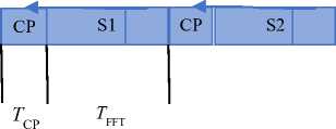
Fig.3. OFDM vs filter bank multicarrier frames.
S1.I
S1.Q
T FFT / 2
S2.I
S2.Q
The extension of FFT to the size of KM aids the implementation of the receiver. Here, the blocks of FFT input overlap in a classic scenario called a sliding window. Subsequently, the data elements are recovered at the FFT output using a weighted de-spreading process. This data recovery depends on the characteristics of the Nyquist filter frequency coefficients. The K multicarrier symbols or KM samples represent the delay in the system when connecting the transmitter and receiver.
Although the scheme depicted in Fig. 2 resembles that of Fig. 1, the operations of IFFT and FFT are preceded and followed by minor operations. However, the complexity resulting from the increased size ( KM ) of FFT in comparison with the earlier M is the major difference between the two schemes.
Additionally, substantial redundancy exists in the computations owing to the overlapping time domains of the IFFT outputs and FFT inputs. This can be reduced using certain schemes.
-
4.3. UFMC
-
4.4. F-OFDM
In the UFMC technique, filtering is applied to the subsets of the band and not to the entire band or separate subcarriers. Fig. 4 depicts a UFMC transmitter accompanied by B sub-bands in the case of a single antenna. ( N + N filter -1)-dimensional time-domain baseband vector x i is generated by the i -th UFMC sub-module with i ϵ {1,2, ..., B }, where N is the number of samples required to represent all sub-bands per symbol without aliasing. This complies with the design criteria used in UFMC, wherein each sub-band holds the QAM symbol vector si with dimension ni × 1, and N relies on the entire bandwidth being covered. N filter represents the length of the filter. Additionally, the sample rates of each sub-band must be aligned.
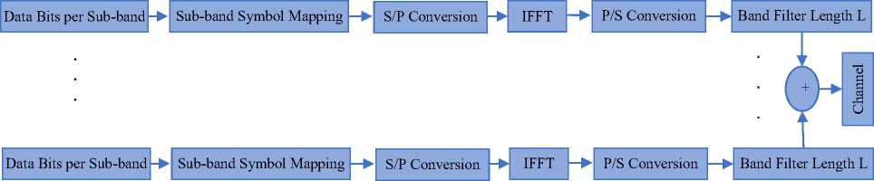
Fig.4. Universal filtered multicarrier transmitter scheme.
One multicarrier symbol is considered from the stream of symbol vectors and the temporal symbol index is excluded to simplify the notation. Single sub-band signals are combined to synthesize the transmit vector x . In contrast to the downlink case, wherein the entire frequency band is covered by the single submodules transporting data to diverse users, coverage of single submodules includes only the portion of the frequency allocated to the user. The N i complex QAM symbols are transformed into time domain before applying the sub-band filter using an inverse discrete Fourier transform spreader. B is selected based on the targets of the system design and the spectrum settings to be handled by the UFMC transmitter.
In the case of a fragmented spectrum, B is generally selected based on the available number of sub-bands. Owing to the occasional existence of other wireless activities generating certain spectrum sub-bands, B can be varied.
Fig. 5 depicts the transmitter scheme where each carrier has N i subcarriers with data arranged in the frequency domain for every F-OFDM symbol. In addition, a CP is affixed and an IFFT corresponding to the N i size is adapted in each carrier to ensure circularity in the received signal. The outputs yielded by a single-stage are fed to a prototype-parameterized filter, and the symbols are transmitted after obtaining the sum of M stages.
Unlike in OFDM, the complexity is increased; this is analyzed in the subsequent sections. Similar to OFDM, low complexity is attributed to the receiver depending on the MN size of the window preceding the stage of MN FFT.
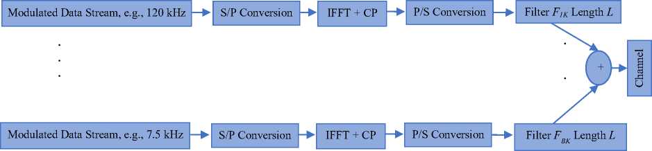
Fig.5. Filtered-OFDM (F-OFDM) transmitter scheme.
The main aspects that differentiate F-OFDM from the traditional OFDM including the asynchronous inter-band transmission resulting from the optimal performance of OOB, an overhead of low-level guard tone between every couple of successive sub-bands, the transmission time interval, CP length, and independent subcarrier spacing for every sub-band, and filtering applied to each sub-band to obtain a bandwidth ≥ 1 resource block (RB).
-
5. Comparison Metrics
-
5.1. Compatibility with 4G
-
5.2. Complexity
-
5.3. Latency
-
5.4. Spectral Confinement
This section compares the four waveforms discussed in Section 4 to outline the merits and demerits based on the following metrics: Compatibility with 4G (LTE), complexity, latency, spectral confinement, spectral efficiency, tail issue, and mobility.
Signals of UFMC and F-OFDM waveforms are compatible with LTE owing to their similarity to OFDM signals. Therefore, they are capable of directly reusing the existing LTE techniques, such as MIMO coding and reference signal design. However, FBMC cannot reuse LTE techniques directly owing to the QAM signaling, which transmits only the symbols of real values.
With the advancement of modulation, certain simple aspects of the technique become complex. However, the OFDM maintains low modem complexity, whereas it doubles in FBMC. As the F-OFDM uses an FIR filter after OFDM modulation, its complexity lies between that of OFDM and FBMC.
The complexity of modulation in UFMC is nearly 8–10 times higher than that of OFDM in the downlink case on the side of the baseline; however, it is more than double in the case of demodulation.
High complexity is a result of using the FFT transform for each RB. Therefore, to modulate 100 blocks in the case of LTE, the complexity reaches a factor of 100. However, a recent report argues that the modulation complexity can be lowered by a factor of 30 by using a frequency-domain realization.
OFDM has the shortest latency for transmitting and receiving because of CP and FTT (T + TCP). Additionally, UFMC has an identical filtering transition period instead of CP. As latency increases naturally with the existence of additional filtering, FBMC exhibits the highest level of latency. The F-OFDM exhibits slightly increased latency as the filter transition period cannot be absorbed without additional buffers.
Two major problems, namely the rectangular pulse and spectral leakage, cause unsatisfactory spectral confinement. The first problem is addressed in FBMC, wherein a new filter, longer than FIR and with better frequency localization, replaces the rectangular filter.
The rectangular pulse in OFDM causes waveform discontinuity, which can be solved by gradually decreasing the envelope of the symbol edges to zero. The second problem that causes waveform discontinuity is overcome by F-OFDM and UFMC using FIR filtering; in FBMC, the envelope of the symbol edges is lowered to zero gradually. Therefore, spectral confinement improvement is better in FBMC than in other schemes.
-
5.5. Spectral Efficiency
The spectral efficiency of a portion of 5G waveforms and concluded that maximum efficiency cannot be achieved by adding a CP of length TCP. Consequently, efficiency is reduced.
T
< 1
n OFDM — т т T + T CP
Conversely, the FBMC scheme does not use CP and follows the Nyquist rate. Therefore, maximum efficiency can be obtained.
T
n FBMC гр 1
T.F where F is the spacing between subcarriers. The maximum efficiency for an orthogonal system can be attained when T.F = 1.
The UFMC scheme uses zero-padding instead of CP, following OFDM modulation. This process isolates the successive symbols following the filtration of time-domain FIR. The number of padded zeros equals the FIR filter length minus 1; therefore, the resultant spectral efficiency equals that of OFDM.
1 T
П — — < 1
UFMC (T + TZP). f t + TCP where TZP is the zero-padding duration, equal to TCP in the case of OFDM.
Finally, the F-OFDM scheme maintains the OFDM process while applying the FIR filtering overhead. Spectral efficiency is not reduced by such filtering. Consequently, the resultant spectral efficiency of F-OFDM also equals that of OFDM.
-
5.6. Tail Issue
-
5.7. Mobility
-
6. Research Methodology
The tail issue occurs in the FBMC scheme as a portion of the transmitted symbols overlaps in the time domain. Therefore, the complete isolation of symbols in burst transmission is not achieved. Conversely, each symbol in OFDM is completely isolated; thus, the tail issue does not exist. Similarly, symbols of UFMC are completely isolated owing to the controlled filter length and any tails resulting from filtering are avoided by zero-padding. However, F-OFDM depends on additional filtering that exceeds the length of CP, resulting in the tail issue.
Owing to the subcarrier filtering process, FBMC has better mobility robustness against Doppler effects in comparison with that of UFMC, F-OFDM, and OFDM, wherein the Doppler effect is handled by widening the subcarrier spacing to serve users of high mobility.
The current study simulates the OFDM scheme presenting the three variants of its waveform by applying transmission and reception. The objective is to identify a suitable system, by analyzing the properties of each waveform to understand how each can benefit 5G technologies.
Input:
Data Stream
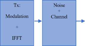
Demodulation
Fig.6. Basic flowchart of the simulation code.
Rx:
FFT
+
Constellation Input vs. Output
Measurements:
PSD BER PAPR
Fig. 6 illustrates the code skeleton of the scheme. Modulation and computation of the IFFT are the major operations in the transmitter before noise accompanies the transmitted signal through the receiver. Here, demodulation, FFT, and transmission of the received bits are computed and compared to calculate PSD, BER, and PAPR. Results were obtained using MATLAB.
16-QAM, 64-QAM, and 256-QAM modulations were used for testing. In this study, the 64-QAM was used for code testing along with the single-path accompanied by an additive white Gaussian noise channel.
Input data:
-
• N = 1024 = Number of carriers and FFT size used to generate the signal.
-
• N used = 600 = Number of nonzero used carriers (50 RB of 12 subcarriers each).
-
• Guarda = 1 × 212 = Guard period.
-
• Bandcenter = 212.
-
• CP = 72 = Cyclic prefix length.
-
• Symbols = 1000 = OFDM transmission symbols.
-
• Testsymbols = 3 = Number of symbols to estimate the channel.
-
• M = 64 = Modulation order.
-
• K = 6 = Bits per symbol.
UFMC specific parameters:
-
• Num-subband = 10 = Number of sub-bands.
-
• Size-subband = 20 = Sub-band symbol duration.
-
• Alpha = 40 = Side-lobe attenuation in dB.
-
• Bandcenter = 412.
-
• L-ufmc = 73 = Filter length (CP + 1).
FBMC specific parameter:
-
• K-factor = 4
-
7. Results and Discussion
-
7.1. PSD
-
7.2. BER
This section examines the performance of each waveform and compares the results of OFDM with that of FBMC, UFMC, and F-OFDM. The probability of error, PAPR, and PSD are the metrics used to evaluate the performance.
Fig. 7 depicts the differences between UFMC, F-OFDM, FBMC, and OFDM in terms of PSD (dB) and the function of normalized frequency.
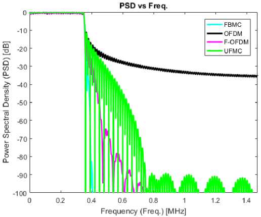
Fig.7. Comparison of power spectral density between OFDM, universal filtered multicarrier, F-OFDM, and filter bank multicarrier.
The smallest power in the OOB was observed in FBMC in comparison with the other waveforms. Therefore, FBMC had the most optimal PSD.
Fig. 8 compares FBMC, F-OFDM, UFMC, and OFDM in terms of BER. The figure validates the principle of higher BER existing at higher modulation levels. In other words, the BER increases with the modulation level.
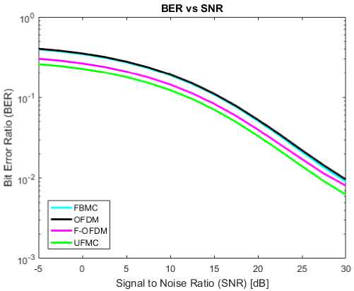
Fig.8. Comparison of bit error rate between OFDM, universal filtered multicarrier, F-OFDM, and filter bank multicarrier.
The simulation results prove that both FBMC and OFDM share the same levels of BER, which are lower than those of F-OFDM and UFMC. Therefore, F-OFDM and UFMC exhibit an optimal BER.
-
7.3. Peak-to-Average Power Ratio (PAPR)
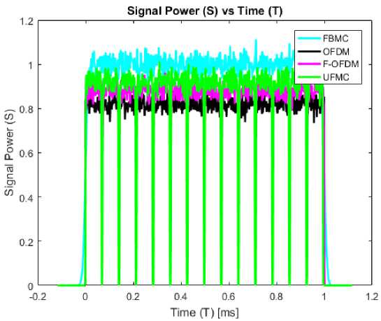
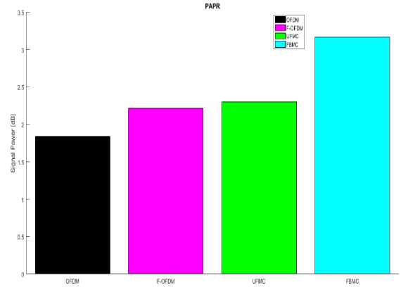
The amplitude can be maintained constant at a given CP, reducing the PAPR, which applies to power amplifiers. However, the PAPR problem increases owing to the filtering process. Therefore, OFDM exhibits the best PAPR in comparison with that of FBMC, F-OFDM, and UFMC. Additionally, the absence of CP results in an inferior PAPR in FBMC.
The theoretical assumption of the study is confirmed by Fig. 9, which represents the signal power and the PAPR.
(a)
(b)
Fig.9. Comparison between OFDM, UFMC, F-OFDM, and FBMC in terms of (a) signal power and (b) peak-to-average power ratio.
Based on the simulation results, the advantages and disadvantages of each waveform are presented in Table 1.
Table 1. Advantages and disadvantages of OFDM, F-OFDM, UFMC, and FBMC waveforms
|
No. |
Waveform |
Advantages |
Disadvantages |
|
1 |
OFDM |
|
|
|
2 |
F-OFDM |
therefore, it is useful for IoT as the cell has numerous short data burst devices. |
- Complexity of implementation is high in comparison with that of OFDM. |
|
3 |
UFMC |
|
|
|
4 |
FBMC |
|
|
-
8. Conclusions
To identify the suitable waveforms for 5G, this study has examined and compared the performance of three candidate waveforms with that of OFDM to validate the qualifications of each waveform to meet the requirements of 5G. The comparison was based on parameters such as spectral efficiency, tail issue, spectral confinement, mobility, latency, complexity, and compatibility with 4G (LTE).
The simulation results show that despite the low spectral efficiency in F-OFDM owing to the lack of CP, it achieved optimal results, demonstrating that it can be easily implemented in 5G. As F-OFDM exhibited high flexibility, asynchronous transmission, a simple transceiver, reduced interference with neighboring subcarriers, and low OOB emissions, it can serve all types of mMTC applications.
Despite its high transceiver complexity resulting from the large filter length, the FBMC exhibited low OOB emissions, low BER, and the most optimal spectral efficiency owing to OQAM modulation. Therefore, it is the most suitable for both eMBB and URLLC applications. Additionally, UFMC was determined to be suitable for mMTC applications owing to its short data burst ability and non-orthogonality.
Nomenclatures
K Sub-symbol number in block transmission techniques
M Maximum number of subcarriers = IFFT size
T Period of sampling (one unity)
Ts Duration of one OFDM symbol a Symbol transmitted over each carrier in a complex constellation c Symbol transmitted over each carrier in a real-valued constellation
Abbreviations
BER CP
FFT FIR
IFFT IoT LTE
MIMO OFDM
OOB PAPR
PRB PSD QAM
RB URLLC
Bit error rate Cyclic prefix Fast Fourier transform Finite impulse response Inverse fast Fourier transform Internet of Things Long term evolution Multiple-input and multiple-output Orthogonal frequency division multiplexing Out of band Peak-to-average power ratio Physical resource block Power spectral density Quadrature amplitude modulation Resource block
Ultra-reliable and low latency communications
Acknowledgment
The author would like to thank the University of Alkafeel for the support of this research.
References Overview and Comparison of Candidate 5G Waveforms: FBMC, UFMC and F-OFDM
- H. Dun, C. C. J. M. Tiberius, and G. J. M. Janssen, “Positioning in a multipath channel using OFDM signals with carrier phase tracking,” IEEE Access, vol. 8, pp. 13011–13028, 2020. doi:10.1109/ACCESS.2020.2966070
- G. Shyam Kishore and H. Rallapalli, “Towards 5G: A survey on waveform contenders,” in Advances in Decision Sciences, Image Processing, Security and Computer Vision, vol. 4, S. Sataphathy, K. Raju, K. Shyamala, D. Krishna, and M. Favorskaya, Eds., Springer, Cham, 2020, pp. 243–250, 2020. doi:10.1007/978-3-030-24318-0_29
- J. Navarro-Ortiz, P. Romero-Diaz, S. Sendra, P. Ameigeiras, J. J. Ramos-Munoz, and J. M. Lopez-Soler, “A survey on 5G usage scenarios and traffic models,” IEEE Commun. Surv. Tutor., vol. 22, pp. 905–929, 2020. doi:10.1109/COMST.2020.2971781
- A. Zahra, Q. U. Khan, and S. A. Sheikh, “Comparative analysis of quaternion modulation system with OFDM systems,” Int. J. Electron. Lett., vol. 9, pp. 1–10, 2021. doi:10.1080/21681724.2020.1725985
- Emoghene Ogidiaka, Francisca Nonyelum Ogwueleka, Martins Ekata Irhebhude, " Game-Theoretic Resource Allocation Algorithms for Device-to-Device Communications in Fifth Generation Cellular Networks: A Review", International Journal of Information Engineering and Electronic Business(IJIEEB), Vol.13, No.1, pp. 44-51, 2021. DOI: 10.5815/ijieeb.2021.01.05
- S.Murugan, " Compact MIMO Shorted Microstrip Antenna for 5G Applications", International Journal of Wireless and Microwave Technologies(IJWMT), Vol.11, No.1, pp. 22-27, 2021.DOI: 10.5815/ijwmt.2021.01.03
- Akinyinka Olukunle Akande, Cosmas Kemisdrin Agubor, Olusola Kunle Akinde, Longinus Sunday Ezema, Samuel Okechukwu Okozi, " Development of a New Diversity Scheme in 5G Network at 28 GHz Millimter-wave Frequency for Digital Mobile System", International Journal of Wireless and Microwave Technologies(IJWMT), Vol.11, No.1, pp. 47-62, 2021.DOI: 10.5815/ijwmt.2021.01.05
- P. Banelli, G. Colavolpe, L. Rugini, and A. Ugolini, “Post-OFDM modulations for 5G and beyond,” University of Perugia, University of Parma, 2019. [Retrieved November 02, 2021, from https://www.5gitaly.eu/2018/wp-content/uploads/2019/01/5G-Italy-White-eBook-Post-OFDM-modulations.pdf]
- Z. E. Ankaralı, B. Peköz, and H. Arslan, “Enhanced OFDM for 5G RAN,” ZTE Commun., vol. 15(S1), pp. 11–20, 2020. [Retrieved November 02, 2021, from https://res-www.zte.com.cn/mediares/magazine/publication/com_en/article/2017S1/464712/P02017072460836
- 7082620.pdf]
- S. Thiyagarajan and S. Veerappan, “Performance analysis of UFMC and its comparison with CP-OFDM,” Int. J. Eng. Tech., vol. 4(2), pp. 776–780, 2018. doi:10.29126/23951303/IJET-V4I2P121
- N. S. Sathiyapriya, “Implementation and study of universal filtered multi carrier under carrier frequency offset for 5G,” Int. J. Electron. Commun., vol. 4(4), pp. 1–5, 2015. [Retrieved November 02, 2021, from https://ipasj.org/IIJEC/Volume4Issue4/IIJEC-2016-04-17-1.pdf]
- G. Kongara, C. He, L. Yang, and J. Armstrong, “A comparison of CP-OFDM, PCC-OFDM and UFMC for 5G uplink communications,” IEEE Access, vol. 7, pp. 157574–157594, 2019. doi:10.1109/ACCESS.2019.2949792
- A. N. Ibrahim and M. F. L. Abdullah, “The potential of FBMC over OFDM for the future 5G mobile communication technology,” AIP Conf. Proc., vol. 1833(1), 020001, 2017. doi:10.1063/1.5002019
- A. J. Ramadhan, “T-S3RA: Traffic-aware scheduling for secure slicing and resource allocation in SDN/NFV enabled 5G networks,” Int. J. Eng. Tre. Tech., vol 69(7), pp. 215-232, 2021. doi: 10.14445/22315381/IJETT-V69I7P229
- A. J. Ramadhan, “Implementation of 5G FBMC PHYDYAS prototype filter,” Int. J. Appl. Eng. Res., vol. 12(23), pp. 13476–13481, 2017. [Retrieved November 02, 2021, from http://www.ripublication.com/ijaer17/ijaerv12n23_63.pdf]
- A. J. Ramadhan, “Overview and implementation of the two most important candidate 5G waveforms,” J. Theoret. Appl. Inform. Tech., vol. 97(9), pp. 2551–2560, 2019. [Retrieved November 02, 2021, from http://www.jatit.org/volumes/Vol97No9/9Vol97No9.pdf]
- A. J. Ramadhan, “Implementation of a 5G filtered-OFDM waveform candidate,” Int. J. Eng. Res. Tech., vol. 12, pp. 500–507, 2019. [Retrieved November 02, 2021, from http://www.irphouse.com/ijert19/ijertv12n4_07.pdf]
- D. Zubov, U. Kose, A. J. Ramadhan, A. Kupin “Mesh Network of eHealth Intelligent Agents in Smart City: A Case Study on Assistive Devices for Visually Impaired People,” CEUR Work. Proc., vol. 2255, pp. 65–81, 2018. [Retrieved November 02, 2021, from http://ceur-ws.org/Vol-2255/paper7.pdf]
