Patch based image inpainting technique using adaptive patch size and sequencing of priority terms

Author: Anupama S. Awati, Meenakshi. R. Patil
Journal: International Journal of Image, Graphics and Signal Processing @ijigsp
Article in issue: 8 vol.11, 2019.
Free access
Image Inpainting is a system used to fill lost information in an image in a visually believable manner so that it seems original to the human eye. Several algorithms are developed in the past which tend to blur the inpainted image. In this paper, we present an algorithm that improves the performance of patch based image inpainting by using adaptive patch size and sequencing of the priority terms. The patch width (wxw) is made adaptive (proportional) to the area of the damaged region and inversely proportional to standard deviation of the known values in the patch around point of highest priority. If the neighbourhood region is a smooth region then standard deviation is small therefore large patch size is used and if standard deviation is large patch size is small. The algorithm is tested for various input images and compared with some standard algorithm to evaluate its performance. Results show that the time required for inpainting is drastically reduced while the quality factor is maintained equivalent to the existing techniques.
Patch Inpainting, Adaptive Patch Size, sequencing of the priority terms
Short address: https://sciup.org/15016076
IDR: 15016076 | DOI: 10.5815/ijigsp.2019.08.06
Text of the scientific article Patch based image inpainting technique using adaptive patch size and sequencing of priority terms
Published Online August 2019 in MECS
Image inpainting is used to rebuild the missing area in an image. The intend of image inpainting is to fill in the absent area in an image which is unseen to human eyes. There are diverse types of image inpainting techniques such as exemplar based image inpainting, texture synthesis based image inpainting, PDE based image inpainting, hybrid inpainting and Semi-automatic and Fast Inpainting. Image inpainting is also applied for reestablishment of old images, adjustment of red-eye, object eradication in digital photographs, deletion of spots of dust in image, innovative effect by removing objects etc.
To reconstruct large textured regions Criminisi et al. [1, 2] suggested a similar patch copy and paste method. A similar patch from the surrounding known regions is searched by using similarity criteria to inpaint the missing pixels. This method involves two terms that are data term and confidence term which define the priority of the pixels to be filled first and to propagate structure as well as texture. By properly selecting similar patches the damaged region is filled by copying pixels from the corresponding similar patches i.e exemplars.
The author of reference [5] expands an exemplar based image inpainting technique by integrating Bézier curves to build missing edge information. The foundation of this technique is the contour lines restoring and exemplar based image inpainting technique with mean shift segmentation to understand color segmentation in damaged image. Then, Bézier curve is utilized to join the missing contour lines to rebuild main structure in damaged area. Finally the algorithm selects a best patch from the source to complete the inpainting procedure. Image inpainting [6] methods are classified as exemplar or non-exemplar, linear or nonlinear, isotropic or anisotropic to facilitate the propagation in particular direction which takes into account the curvature of the structure present in the nearby known areas. Non exemplar methods perform better for straight lines, curves, and for inpainting small regions and fail for recovering the texture of large areas. Multiple candidate patches are selected for each target patch using a Gaussian-weighted nonlocal texture similarity measure in [7]. Exemplar based technique [8] is improved by using adaptive size of window; the size of window is selected based on patch sparsity. Structure tensors [9] are used to enhance the filling order priority and template matching. The technique used to define similarity between patches is based on Hellinger distance[10]. Time complexity [11] is reduced by converting the global search matching algorithm into local one. Image gradient [12] is used as a similarity metric for searching similar patches. Structure sparsity based on sparseness is used to define priority function [13] with higher priority given to patch with larger structure sparsity, which is generally located at the structure, and is selected for further inpainting. A patchbased image inpainting [14] is based on variance and structure consistency between the adjacent points in the target region.
Criminisi’s algorithmic performance can be enhanced by using variable patch size [15] and confidence value is modified based on search accuracy. Inpainting [16] by separating the image into foreground and back ground using the graph cut algorithm. The foreground and back ground regions are inpainted separately with best-match patches taken from the regions respectively. The exemplar-based image inpainting [17] method is enhanced by reduced source region and modified fill front updating scheme. A multi-scale [18] patch log likelihood imposes the patch-based model on different scale patches extracted to narrow the gap to the global modeling while preserving the local treatment. A MRF-based inpainting [19] uses context-aware approach to reduce the number of possible labels per MRF node and choose them in such a way that they better fit the surrounding context. The refined patch is obtained by filtering using α (alpha)-trimmed mean filter to inpaint the target patch pixel-by-pixel. Traditional exemplarbased inpainting technique is enhanced by a patch shifting scheme [20] which provides more appropriate target patch.
-
A. Key Issues And Core Technologies In Inpainting .
The problem with most inpainting methods is they cannot proficiently reconstruct huge damage regions. In numerous patch based methods the patch width is fixed and is not adaptive to damaged area and information content in the neighborhood region. For patch based method the priority calculations are done for each iteration and more time is spent on calculation of boundary and new priority term. This can be reduced to decrease time taken by the algorithm to inpaint the entire region. The core technologies in inpainting include diffusion based, non diffusion based. Another key issue is to determine the point on the boundary of the damaged region at which the inpainting procedure is to be initiated. Also efficient evaluation methods for evaluating inpainted images is another key issue in inpainting.
-
B. Related Work And Motivation
Many authors have proposed algorithm for modification in Patch based inpainting to improve quality of inpainting and to reduce time required for inpainting. The modifications proposed by authors are in calculation of priority term, search strategy and refining multiple patches for accuracy. No attempt has been made for reducing time required for inpainting procedure using adaptive patch size and reducing priority calculations. This can be achieved by calculating the patch width based on the damaged area and the statistical properties of the neighborhood regions. Minimum patch width is selected and increased adaptively to suit the neighborhood region. This width is increased to a maximum value and then decreased based on the area to be inpainted which is iteratively updated.
Our main contributions are
-
(i) The conventional patch based technique performs well for reconstructing straight lines, but fails for reconstructing edges and corners. The patch based method involves priority calculations and matching criterion. The contribution is gradient function and curvature finding term in priority calculations. These terms identify the corners and edges and give high priorities to pixels at the edges and corners.A new equation is suggested for priority of a point on the boundary as a combination of curvature term and gradient
function with weight factors a and b .
-
(ii) Optimise the value of a and b for improved performance parameters.
-
(iii) Assigning patch width based on damaged area, statistical and spatial properties of the pixels in the neighborhood.
-
(iv) Reducing the calculation time in each iteration by sequencing the priority terms.
-
II. Background
A. Patch Based Image Inpainting
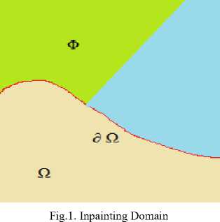
The exemplar based image inpainting is an important category of inpainting algorithms. The exemplar based image inpainting is an efficient technique of reinstallation of big target regions. Consider a region Ω to be inpainted (target region) and let ∂ Ω be its boundary between the known and unknown region and Φ is the source region as illustrated in figure 1.
The exemplar based image inpainting selects the best matching patches from the known area, whose similarity is determined by certain metrics, and insert into the target patches in the missing area. According to the filling order, the technique fills structures in the missing regions using spatial information of neighbouring regions. The exemplar based image inpainting consists of the following steps:
-
1) Determine the Target Region by finding the damaged pixels.
-
2) Computing Filling Priorities to determine the point on the boundary at which the filling procedure is to be initiated based on the information content of the image.
-
3) Searching similar patches based on minimum mean squared error of the pixel values of source patch and target patch.
-
4) Copying the most similar patch at the target region.
-
5) Updating Image Information to proceed with the filling process by updating the boundary of the target area and filling priorities.
-
III. Proposed Algorithm
-
A. Priority Term And Its Significance
The priority term gives us an idea about the most suitable patch to be filled first around the damaged pixel ‘p’ on the border of the damage cover, (drawn/chosen by user).
There is intervention of user as image inpainting is an image editing tool. Since the patch being chosen is a square one, it is quite a possibility that next suitable patch centre lies on the square that was filled during earlier iteration, in the case where the priority is chosen based on the number of pixels known in the destination patch. Hence the patch fill order follows the previous filled patches proceeding and filling the interior of the damaged region, moving towards filling some of the borders which is not feasible in cases where image structure is to be restored. To solve this problem fill order is chosen to begin with most suitable pixel and fill the complete exterior border first and moving inwards in circular manner during the next iterations.
In this work the priority of the patch to fill is decided based on the research [26] of the patch around destination pixel ‘p’, which takes into consideration the known as well as unknown pixels of patch.
-
B. Methodology
To recover the target region (masked region) in the image the priority Pr(p) of every pixel is calculated on the boundary of damaged region. Referring to figure 2 for a patch Ψ p, δΩ is the contour of the target region, np is the normal to the contour and V Ip 1 is the isophotes (direction and intensity) where I is the entire image while Φ is the undamaged area and Ω is the damaged area. We have defined Priority as follows
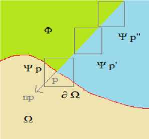
Fig.2. Patch based inpainting flow direction
PAp^ = d^ r i(P) + bPr2(p) (1)
P r i(P) = CT(p)
Dr(p) ф ^^^^^^^^^^^^^^^^^^
2na(,Kr(p)+a)
CAp)=0 for target region, C(p)= 1 for source region
Pr2(p) = |VI|+log(|VI| + 1)(3)
«^■Ш(4)
Dr(p) = : •
In the above equations
P r i(p) is curvature term.
P r 2(p) is gradient term.
V I is gradient of the pixel p a and b are weight factors. о and a adjustment parameter np is the normal to the contour δ Ω
VIpL is the isophotes perpendicular to 5 fi
These values of a and b are selected as 0.4 and 0.6 respectively based on the best results obtained for SSIM for many images. о and a adjustment parameters are chosen as 0.8.
The curvature term is added to priority equation to aid the filling of pixels along the curve. Kp is curvature of isophotes (line of equal intensities) and represents geometric information of the image. α is a fine-tuning parameter for higher accuracy added in manual way. Based on type of input image this parameter can be adjusted. This factor has the capability to preserve more low-frequency contour features in the smooth areas, maintain high-frequency marginal features and also enhance medium-frequency texture details.
In patch based image inpainting the patch width w is fixed as either 5x5 or 7x7 etc. The initial value of patch width is fixed as w1
= area *
100 ^imagesize
This patch width can be made adaptive based on the damaged area and the standard deviation at the patch across highest priority. The patch width can be defined as w = w1 + rowid(1 + 2 *
(area* "00 J ) (7)
V std(patch)/y v 7
^ т (р) Values are sorted according to descending order. Let the highest priority value be H. All the priority points lying in the range of R= ( 0.96 * H, H) is determined. These priority values correspond to row column information on the boundary between known and unknown region All the values from H to 0.96*H is arranged in descending order. The patch around H is extracted and a similar patch is found from the known region using minimum value of sum squared distance.
^ qr=arg™^d(Tp-,Tq) (8)
The фдт is the summation of squared differences of the already known pixels in the current patch and the selected patch. After finding the most suitable patch in the source region of the image copy and update the patch to the target region. And repetitively implement the above mentioned steps until all the pixel positions having priority values in the range R are exhausted. The patch width is adaptive so the new value of w is calculated using equation The algorithm is continued by finding the new boundary, new priority values and sequencing the values till the entire region is filled.
-
IV. Experiment simulation and Result Analysis
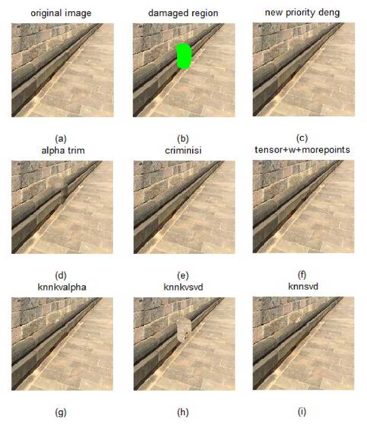
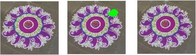
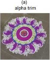
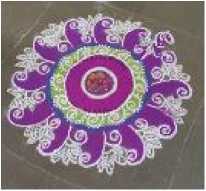
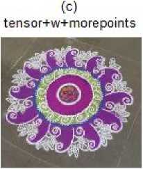
To test the algorithm we have taken original images of heritage sites. As image inpainting is an image editing tool user intervention is needed in the form of marking the region to be inpainted. In order to evaluate our algorithm we have compared our results with the basic Criminisi’s[1] algorithm, alpha trimmed filter [21], EBIIMPD [22], knnkvalpha (kn similar patches in the vicinity of damaged area with alpha trimmed filter) [24], knnsvd (kn similar patches with SVD for patch refinement) [25] and knnkvsvd (kn similar patches in the vicinity of damaged area with SVD for patch refinement). Parameters which are important in deciding the quality of an image are mean square error (MSE), luminance(L), cross correlation(XK), absolute difference (AD), normalized absolute error (NAE), structural content(SC), PSNR and structural similarity [23]. The quality factor is defined as the product of all the above listed parameters. From table 1 to 5 we see that the proposed method performs considerably better in terms of quality factor and time taken. Output image of proposed work and of other standard algorithm are as shown in figure 3 to 6.
-
V. Conclusion
In this paper we have proposed algorithm that enhances the performance of patch based image inpainting by using adaptive patch size and sequencing of the priority terms to provide faster inpainting. The patch size is made adaptive to the area of damaged region and inversely proportional to standard deviation of the known values in the patch around point at which patch priority is highest. For smooth regions patch width is large and small for structured regions. By adaptively selecting the patch width, the performance is enhanced in the form of time taken. Also sequencing of the patches reduces the over head of the algorithm in terms of calculation time and improves the speed of inpainting. In future the algorithm can be implemented by finding the priority by using standard deviation of known pixels in the neighbourhood region (wxw) of a point on the boundary.
Table 1. Performance parameter for image 1
|
Method |
Q |
SNR |
SS |
L |
MSE |
XK |
NAE |
AD |
SC |
Time |
|
EBIIMPD[22] |
34.7467 |
35.3991 |
0.9894 |
1.0000 |
0.9999 |
1.0005 |
0.9957 |
0.9977 |
0.9983 |
109.9101 |
|
Alpha[21] |
30.4327 |
31.2753 |
0.9846 |
1.0000 |
0.9997 |
1.0001 |
0.9933 |
0.9971 |
0.9979 |
438.8572 |
|
Criminisi [1] |
36.9477 |
37.3473 |
0.9932 |
1.0000 |
0.9999 |
1.0000 |
0.9970 |
0.9995 |
0.9996 |
16.8118 |
|
Proposed |
34.8547 |
35.3963 |
0.9890 |
1.0000 |
0.9999 |
0.9997 |
0.9963 |
0.9999 |
0.9999 |
19.2942 |
|
Knnkvalpha[24] |
33.9543 |
34.5061 |
0.9906 |
1.0000 |
0.9999 |
1.0003 |
0.9962 |
0.9984 |
0.9985 |
33.8665 |
|
knnkvsvd |
22.3133 |
24.3050 |
0.9772 |
0.9999 |
0.9988 |
1.0075 |
0.9841 |
0.9715 |
0.9766 |
150.1212 |
|
Knnsvd[25] |
32.4530 |
3.0775 |
0.9887 |
1.0000 |
0.9998 |
1.0003 |
0.9956 |
0.9984 |
0.9982 |
59.5980 |
new priority deng damaged region knnsvd knnkvalpha knnkvsvd original image
(c) tensor+w+morepoints alpha trim cnminisi
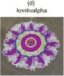
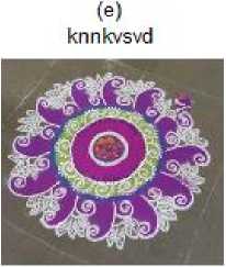
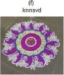
Fig.3. (a) Original image (b) Damaged image (c) New Priority deng (d) alpha trim (e) criminisi (f) Proposed (g) knnkvalpha (h) knnkvsvd (i) knnsvd
Table 2. Performance parameter for image 2
|
Method |
Q |
SNR |
SS |
L |
MSE |
XK |
NAE |
AD |
SC |
Time |
|
EBIIMPD[22] |
28.1607 |
29.4485 |
0.9841 |
1.0000 |
0.9996 |
0.9947 |
0.9887 |
0.9949 |
0.9935 |
93.4585 |
|
Alpha[21] |
29.7969 |
30.9186 |
0.9873 |
1.0000 |
0.9997 |
1.0034 |
0.9899 |
0.9927 |
0.9902 |
672.7298 |
|
Criminisi [1] |
28.1040 |
29.5340 |
0.9858 |
1.0000 |
0.9996 |
0.9929 |
0.9904 |
0.9921 |
0.9898 |
18.4781 |
|
Proposed |
27.6559 |
29.1193 |
0.9818 |
1.0000 |
0.9996 |
0.9933 |
0.9893 |
0.9937 |
0.9911 |
24.0895 |
|
Knnkvalpha[24] |
28.9223 |
30.2055 |
0.9882 |
1.0000 |
0.9997 |
0.9936 |
0.9916 |
0.9930 |
0.9907 |
70.9303 |
|
knnkvsvd |
27.1618 |
28.4810 |
0.9834 |
1.0000 |
0.9995 |
1.0046 |
0.9883 |
0.9914 |
0.9857 |
183.0305 |
|
Knnsvd[25] |
28.0735 |
29.3960 |
0.9844 |
1.0000 |
0.9996 |
0.9934 |
0.9906 |
0.9950 |
0.9911 |
63.8052 |
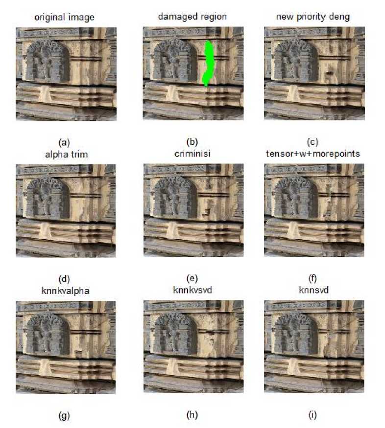
Fig..4. (a) Original image (b) Damaged image (c) New Priority deng (d) alpha trim (e) criminisi (f) Proposed (g) knnkvalpha (h) knnkvsvd (i) knnsvd
Table 3. Performance parameter for image 3
(b) criminisi
(g) (h) 0)
Fig.5. (a) Original image (b) Damaged image (c) New Priority deng (d) alpha trim (e) criminisi (f) Proposed (g) knnkvalpha (h) knnkvsvd (i) knnsvd
Table 4. Performance parameter for image 4
|
Method |
Q |
SNR |
SS |
L |
MSE |
XK |
NAE |
AD |
SC |
Time |
|
EBIIMPD[22] |
28.1458 |
29.9131 |
0.9708 |
1.0000 |
0.9997 |
0.9943 |
0.9886 |
0.9943 |
0.9920 |
114.1380 |
|
Alpha[21] |
29.7396 |
31.1850 |
0.9702 |
1.0000 |
0.9997 |
0.9970 |
0.9898 |
0.9996 |
0.9966 |
668.2251 |
|
Criminisi [1] |
30.1367 |
31.4838 |
0.9781 |
1.0000 |
0.9998 |
0.9960 |
0.9921 |
0.9961 |
0.9944 |
27.4373 |
|
Proposed |
28.5658 |
30.1150 |
0.9704 |
1.0000 |
0.9997 |
0.9956 |
0.9904 |
0.9973 |
0.9945 |
37.0576 |
|
Knnkvalpha[24] |
24.3450 |
26.7072 |
0.9658 |
1.0000 |
0.9993 |
0.9880 |
0.9859 |
0.9865 |
0.9829 |
170.6650 |
|
knnkvsvd |
28.3689 |
29.7538 |
0.9681 |
1.0000 |
0.9996 |
0.9974 |
0.9896 |
0.9998 |
0.9983 |
373.1027 |
|
Knnsvd[25] |
21.7092 |
24.5257 |
0.9620 |
0.9999 |
0.9988 |
0.9829 |
0.9810 |
0.9776 |
0.9773 |
115.6693 |
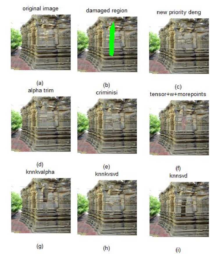
Fig. 6. (a) Original image (b) Damaged image (c) New Priority deng (d) alpha trim (e) criminisi (f) Proposed (g) knnkvalpha (h) knnkvsvd (i) knnsvd
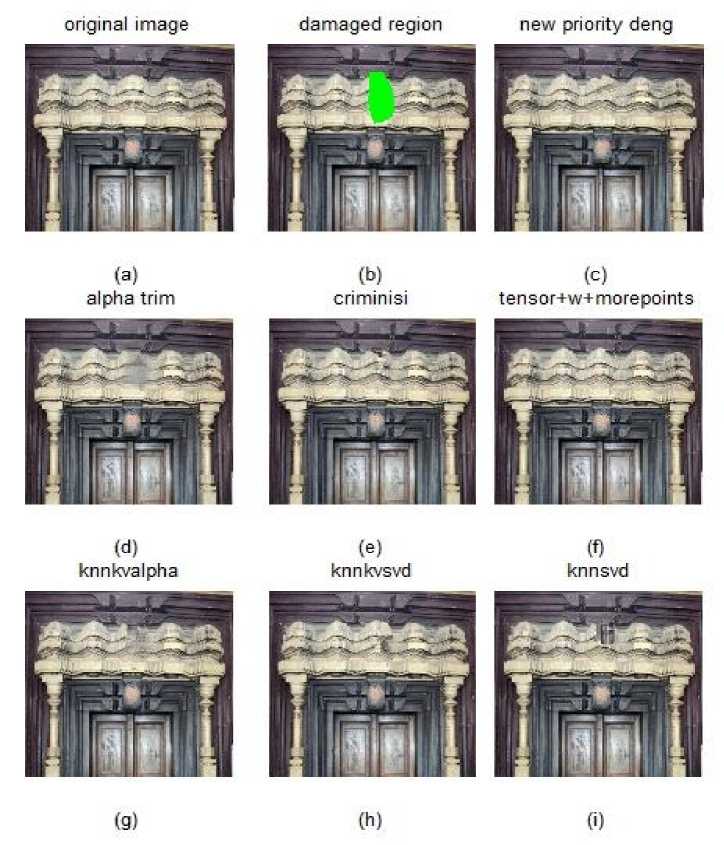
Fig.7. (a) Original image (b) Damaged image (c) New Priority deng (d) alpha trim (e) criminisi (f) Proposed (g) knnkvalpha (h) knnkvsvd (i) knnsvd
Table 5. Performance parameter for image 5
|
Method |
Q |
SNR |
SS |
L |
MSE |
XK |
NAE |
AD |
SC |
Time |
|
EBIIMPD[22] |
29.8522 |
31.1932 |
0.9808 |
1.0000 |
0.9997 |
0.9948 |
0.9919 |
0.9964 |
0.9925 |
114.6434 |
|
Alpha[21] |
28.1807 |
30.1477 |
0.9770 |
1.0000 |
0.9997 |
0.9903 |
0.9901 |
0.9919 |
0.9841 |
556.9826 |
|
Criminisi [1] |
28.1612 |
29.6971 |
0.9827 |
1.0000 |
0.9996 |
0.9919 |
0.9919 |
0.9931 |
0.9879 |
16.8709 |
|
Proposed |
30.2279 |
31.3796 |
0.9839 |
1.0000 |
0.9998 |
0.9955 |
0.9933 |
0.9966 |
0.9938 |
9.7320 |
|
Knnkvalpha[24] |
26.6894 |
28.6468 |
0.9784 |
1.0000 |
0.9995 |
0.9888 |
0.9900 |
0.9907 |
0.9825 |
129.4109 |
|
knnkvsvd |
29.6463 |
30.8050 |
0.9837 |
1.0000 |
0.9997 |
0.9953 |
0.9928 |
0.9966 |
0.9938 |
183.9258 |
|
Knnsvd[25] |
24.6228 |
26.7727 |
0.9790 |
1.0000 |
0.9993 |
0.9854 |
0.9879 |
0.9869 |
0.9785 |
122.1882 |
References Patch based image inpainting technique using adaptive patch size and sequencing of priority terms
- A. Criminisi, P. Pérez, and K. Toyama. Object removal by exemplar-based inpainting. In Proc. IEEE Int. Conf. on Computer Vision and Pattern Recognition, volume 2, page 721, Los Alamitos, CA, USA, 2003. IEEE Computer Society.
- A. Criminisi, P. Pérez, and K. Toyama. Region filling and object removal by exemplar-based image inpainting. IEEE Trans. Image Processing, 13:1200–1212, 2004.
- G.Anto Silviya and V.R.Bhuma, “Exemplar-Based Image Inpainting by Laplacian Approximation Method Using Spatiogram”, International Journal of Engineering Research and Applications (IJERA) ISSN: 2248-9622.
- Aur´elie Bugeau, Vinh-Thong Ta and Nicolas Papadakis, “Variational Exemplar-based Image Colorization”, HAL 00803219, Version-1, March-2013.
- Jason C. Hung, Chun-Hong Hwang, Yi-Chun Liao, Nick C. Tang and Ta-Jen Chen, “Exemplar-based Image Inpainting base on Structure Construction”, Journal Of Software, Vol. 3, No. 8, November 2008.
- C Guillemot, O Le Meur, “Image inpainting: Overview and recent advances”, IEEE signal processing magazine, 2014.
- Ding Ding , Sundaresh Ram and Jeffrey J. Rodríguez “Image Inpainting Using Nonlocal Texture Matching and Nonlinear Filtering”, IEEE Transactions On Image Processing, Vol. 28, No. 4, April 2019.
- Fan Qian, Zhang Lifeng, Hu Xuelong, “Exemplar-based image inpainting algorithm using adaptive sample and candidate patch system”, 2015 IEEE 12th Interational Conference on Electronic Measurement & Instruments ICEMI'2015.
- Olivier Le Meur, Josselin Gautier Christine Guillemot, “Examplar-Based Inpainting Based On Local Geometry”, Image Processing (ICIP), 2011 ieeexplore.ieee.org.
- R. Martinez-Noriega, A. Roumy G. Blanchard, “Exemplar·Based Image Inpainting: Fast Priority And Coherent Nearest Neighbor Search”, 2012 IEEE International Workshop On Machine Learning For Signal Processing, SEPT. 23-26, 2012
- LIU Ying, LIU Chan-juan, ZOU Hai-lin, ZHOU Shu-sen, SHEN Qian, “A Novel Exemplar-based Image Inpainting Algorithm”, International Conference on Intelligent Networking and Collaborative Systems IEEE computer society.
- Kaushik kumar R. Patel, Lalit Jain, “A Novel Approach to Exemplar Based Image Inpainting”, IEEE Technology for Humanity.
- Zongben Xu and Jian Sun Image Inpainting by Patch Propagation Using Patch Sparsity IEEE Transactions On Image Processing, Vol. 19, No. 5, May 2010 1153.
- A patch-based image inpainting based on structure consistence Hui-Yu Huang Department of Computer Science and Information Engineering, National Formosa University 64, Wun-Hua Rd., Huwei, Yunlin 632, Taiwan E-mail: hyhuang@nfu.edu.tw Chun-Nan Hsiao 2010 IEEE
- 2011 4th International Congress on Image and Signal Processing An improved scheme for Criminisi’s inpainting algorithm Song Zhang, Xuya Zhou 2011 IEEE
- Bi-Layer Inpainting For Novel View Synthesis Hwasup Lim, Yong Sun Kim, Seungkyu Lee, Ouk Choi, James D. K. Kim, and Changyeong Ki 2011 18th IEEE International Conference on Image Processing
- Proceedings of the 2012 Interational Conference on Machine Learing and Cybernetics, Xian, 15-17 July, 2012 Fast Exemplar-Based Image Inpainting Approach Hui-Qin Wang1, Qing Cheni, Cheng-Hsiung Hsieh2>, Peng yul 2012 IEEE
- IEEE Transactions On Image Processing, VOL. 25, NO. 1, JANUARY 2016 249 Multi-Scale Patch-Based Image Restoration Vardan Papyan and Michael Elad,
- IEEE Transactions On Image Processing, VOL. 24, NO. 1, JANUARY 2015 Context-Aware Patch-Based Image Inpainting Using Markov Random Field Modeling Tijana Ruži´ c and Aleksandra Pižurica,
- Sarawut Akinori Nishihara, “Exemplar-Based Image Inpainting With Patch Shifting Scheme”.
- Ding Ding , Sundaresh Ram and Jeffrey J. Rodríguez “Image Inpainting Using Nonlocal Texture Matching and Nonlinear Filtering”, IEEE Transactions On Image Processing, Vol. 28, No. 4, April 2019.
- Deng L-J, Huang T-Z, Zhao X-L (2015) “Exemplar-Based Image Inpainting Using a Modified Priority Definition”. PLoS ONE 10(10): e0141199. doi:10.1371/journal.pone.0141199
- Song Wang Hong Li Xia Zhu Ping Li, “An Evaluation Index Based on Parameter Weight for Image Inpainting Quality”2008 IEEE computer society.
- “Inpainting with Refinement of Vicinity Patches using alpha trim filter for Heritage Sites” in International Journal of Current Engineering and Technology E ISSN 2277–4106, P ISSN 2347 5161©2019 INPRESSCO Vol.9, No.2 (March/April 2019).
- Inpainting of Structural Reconstruction of Monuments Using Singular Value Decomposition Refinement of Patches", International Journal of Image, Graphics and Signal Processing(IJIGSP), Vol.11, No.5, pp. 44-53, 2019.DOI: 10.5815/ijigsp.2019.05.05, in MECS (http://www.mecs-press.org/).
- Image Inpainting using exemplar based technique with improvised data term CTEMS 2018, K.L.S. Gogte Institute of Technology, Belagavi, Dec 2018.
