Performance Analysis of Non-Linear Equalizer in MIMO System for Vehicular Channel

Author: Vikash Kumar Tiwary, Subham Agarwal, Samarendra Nath Sur
Journal: International Journal of Image, Graphics and Signal Processing(IJIGSP) @ijigsp
Article in issue: 11 vol.5, 2013.
Free access
All wireless technologies face the challenges of multipath signal fading, attenuation delay and phase delay which led to the interference between users and there is the possibility of limited spectrum. Linear and Non-Linear receiver is used to combat the effect of multipath signal fading and delay. The linear receiver gives best result in case of static environment but in case of dynamic environmental condition it fails to give better results and hence in order to improve the system performance non-linear receiver is used in dynamic environment condition. As a dynamic channel, Vehicular Channel model is considered because there is growing interest in vehicular networking and it is also a challenging channel model because of the complexity of the environment, and rapid variation in channel conditions. This paper studies the comparison between Zero Forcing (ZF) and Minimum Mean Square Error (MMSE) receiver in the Vehicular Channel. A comparative study between linear equalizer and non-linear equalizer in the Vehicular Channel is done and analyze the effect of the varying modulation and antenna configuration on the performance.
MIMO, zero forcing, minimum mean squared error, Vehicular channel model, Linear equalizer, Non-linear equalizer, V-BLAST
Short address: https://sciup.org/15013107
IDR: 15013107
Text of the scientific article Performance Analysis of Non-Linear Equalizer in MIMO System for Vehicular Channel
In communication system the transmitter sends the information to the channel and after passing through the channel the information gets distorted before it reaches the receiver, the receiver task is to figure out what signal was transmitted and turn the received signal into understandable information. Multiple Input Multiple Output (MIMO) is the use of multiple antennas at both the transmitter and receiver side to improve the communication performance [1]. MIMO has attracted the attention in wireless communication as it offers diversity and increased data rate. Diversity is the main concept used in MIMO which provide the multiple replicas of transmitting signals which help to combat fading and interference [2].
Vehicles can travel through different environments, producing distinctly different channels in e.g. urban area, rural roads, and multi-lane highways. Even within a given area, the location and density of surrounding objects vary dramatically, leading to varying impact on reflected signals. Despite of these challenges, it is useful to model and simulate channels in vehicular networks in a controllable platform. Realistic vehicular channel models provide a basis for analysis and evaluation of wireless vehicular networks by allowing flexible, controllable, repeatable experimentation. Vehicular channels have:
-
(a) Highly variable blockage of Line-Of-Sight (LOS);
-
(b) Location-specific scatters distribution and corresponding fading effects.
The direct LOS path between two communicating vehicles exits when there are no other cars travelling in between, and may be easily interrupted by lane merging of intervening vehicles. Current simulation platforms often overlook the impact and no direct models handle the LOS effects explicitly. Fading effects, which are caused by scatters (objects that reflect signals) in the environment, are location-specific in the vehicular network. Vehicular networks have a unique set of variables scatters. These include road-side ‘stationary’ scatters, such as trees, buildings, and the moving vehicles. Although road-side scatters are stationary, their density and location do change over space as vehicles drive by. Therefore, ‘stationary’ scatters create time-varying impacts on channel fading properties. We have considered three International Telecommunication Union (ITU) vehicular channel models:
-
(a) ITU channel model A and B for Vehicular Test environment.
-
(b) ITU channel model A and B for outdoor to indoor and Pedestrian Test environment.
We chose these particular models because there is growing interest in vehicular networking and it is also a challenging channel model because of the complexity of the environment, and rapid variation in channel conditions [3].
Hence the need for the appropriate equalizer at the receiver end is required so that the information is received. There are two types of equalizer linear equalizer and non-linear equalizer. Non-linear equalization is needed when the channel distortion is too severe for the linear equalizer to mitigate the channel impairments. ZF and MMSE algorithm is implemented in this equalization technique. The ZF and MMSE equalizers are classic functional blocks in digital communication [4]. They are also the building block of a more advanced communication scheme such as Decision feedback equalizer (DFE) or the vertical bell labs layered space time (V-BLAST) architecture [5], [6]. In this paper International Telecommunication Union (ITU) channel model for Vehicular Test Environment and outdoor to indoor and Pedestrian Test environment is considered, and overviews on various channel characteristics.
The remainder of the paper is organized as follows. In section II , a review of the necessary background required to effectively implement our algorithm is presented and the proposed algorithm is described. In Section Ш the results of the proposed algorithm are discussed.
-
II. system model
In this section we will consider the MIMO system modeling and mathematical modeling of the linear and non-linear equalizer in MIMO system.
A. MIMO System
MIMO is the use of multiple antennas at both the transmitter and receiver to improve communication performance. It is one of several forms of smart antenna technology. MIMO Technology has attracted attention in wireless communication. The transmitter and receiver are equipped with multiple antenna elements. The transmit stream go through a matrix channel which consists of multiple receive antennas at the receiver. Then the receiver gets the received signal vectors by the multiple receive antennas and decodes the received signal vectors into the original information.
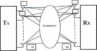
Figure 1 MIMO wireless channel
Consider the MIMO system with N transmit and M receive antennas, where N < M. We assume that the MIMO channel is a continuous flat fading channel and can be denoted by an M*N matrix H with zero mean and unit variance independent identically distributed complex Gaussian entries. If we assume the transmit
Channel State Information (CSI) is not considered, then the M*1 received signal vector r is modelled by r = Hs + n ,
Where r is the received signal, H is the Channel matrix, s is the transmitted signal and n is the additive white Gaussian noise in the signal [7].
B. Linear Equalizer
In Digital communication systems, inter-symbol interference (ISI) and multiuser interference (MUI) are factors that hinder receiver performance. MIMO systems transmit different signals from each transmit element so that the receiving antenna array receives a superposition of all the transmitted signals. All signals are transmitted from all elements once and the receiver solves a linear equation system to demodulate the message. To achieve reliability and high-speed communication, channel equalization can be applied as an important technique to overcome the effect of ISI and MUI. Hence the need for the appropriate equalizer at the receiver end is required so that the information is received. Equalizers are used to combat the effect of the multipath signal fading and delay. In linear equalizer ZF and MMSE algorithm is implemented.
-
1) Zero Forcing (ZF):
Zero Forcing receiver [8], is a Simple linear receiver. It behaves like a linear filter and separates the data streams and thereafter independently decodes each stream with low computational complexity. It minimizes interference but suffers from noise enhancement. The ZF receiver works best with high SNR level. Zero Forcing implements matrix pseudo-inverse (+). The ZF estimated received signal is given by:
x = ( H H H ) - 1 HH . x = H + x
Where the zero forcing decoding matrix is as follows:
S ZF = (HhH) - 1Hh
where superscript H denotes Hermitian transpose.
In reality, zero-forcing equalization does not work with most applications, for the following reasons:
-
a) Even though the channel impulse response has a finite length, the impulse response of the equalizer needs to be infinitely long.
-
b) The channel may have zeroes in its frequency response that cannot be inverted.
-
c) As a consequence, any noise added after the channel gets boosted by a large factor and destroys the overall signal-to-noise ratio.
-
2) Minimum Mean Square Error (MMSE):
The MMSE receiver suppresses both the interference and noise components. This implies that the mean square error between the transmitted symbols and the estimate of the receiver is minimized. Some of the important characteristics of MMSE detector are simple linear receiver, superior performance to ZF and at Low SNR, MMSE becomes matched filter and for very high SNR level decorrelator completely suppress the interference, therefore it provide better performance at higher SNR level. MMSE receiver is another type of linear detector which minimizes the mean squared error between the transmitted symbols. MMSE detector helps to jointly minimize both the noise and interference. Therefore MMSE detector outperforms the ZF detector in the presence of noise.
The MMSE receiver gives a solution of:
x = (—I + H H H) - 1H H .x SNR
The above two linear equalization algorithm is based on multiplying the received vector by a detection matrix and then decoding the symbols separately [9].
Where SNR is the signal to noise ratio, I is the identity matrix and H is the channel matrix.
A common perception about ZF and MMSE is that ZF is the limiting form of MMSE →as∞. SNR Therefore, it is presumed that the two equalizers would share the same output SNRs and consequently, the same uncoded error or outage probability in the high SNR regime. We show, however, that the output SNRs of the N data sub streams using MMSE and ZF are related by p MMSE p ZF +nSNR
Where p ZF (output SNR of ZF equalizer), P mmse (output SNR of MMSE equalizer) and H snr (are statistically independent and is a non-decreasing function of SNR [10].
C. Non-Linear Equalizer
A decision feedback equalizer (DFE) is a nonlinear equalizer that uses previous detector decision to eliminate the ISI on pulses that are currently being demodulated. In other words the distortion on a current pulse that was caused by previous pulses is subtracted. The non-linearity of the DFE is from the nonlinear characteristics of the detector that provides an input to the feedback filter. The basic idea of a DFE is that if the value of the symbols previously detected are known , then the ISI contributed by these symbols can be cancelled out exactly at the output of the forward filter by subtracting past symbol value with appropriate weighting [11], [12].
The advantage of a DFE implementation is the feedback filter, which is additionally working to remove ISI, operates on noiseless quantized levels, and thus its output is free of channel noise.
D. Derivation of DFE-MMSE
Consider the development where bK and wK are the feedback and feedforward filter coefficients derived in minimum-mean-square-sense, by making error orthogonal to the received sequence. Y(t) represents the received signal, the channel input data symbol as xK , and the channel-impulse response as h(t) where n(t) is additive-white Gaussian noise and T is the symbol duration [13].
Y(t) = Z(xm.h(t - mT) + n(t))(6)
The equalizer output error is expressed as ek = b*xK,K-v - w*yK + Nf-1,k where v is expressed as channel memory
The w * feed forward filter taps are expressed
W* = [w* -(Nf -1)W* -(Nf-2)
For a decision delay of A , the corresponding MMSE is expressed as
E{|6k| } = E{(xK -A- wYK + bx(K-1-A))(xK-A- wYK + bx(K-1-A)) } where b is the vector of the coefficient for the feedback filter and XK_A-1 is the vector of the data symbols in the feedback path.
Applying the orthogonality principle by making the error orthogonal to the output we get
E{e K ,Y K } = 0
The auto-correlation matrix is given by
Ryy = (E{Y(k+Nf-1,K)Y*(K+Nf-1,K)}) = Sx 'H'H + ^R. nn where Rnn = N01 Nf and where N0 is the noise power, where I is the identity matrix, the input-output crosscorrelation matrix, where sx is the signal power.
The mean square error is expressed as:
(Rxx - RxyRy1Ryx ) = Sx [OI y + 1 ]
[i Nf + v - H * (HH * + 1/SNRl Nf + v ) - 1H
Simplifying the equation by using the matrix inversion lemma result
S x [OI v + 1 ][l Nf + v - H * (HH * + 1/SNRl Nf + v ) - 1H]0;I v + i ] = N o [cI v + i l(* + 1 / SNRl Nf + v ) - 1[0; Iv + i ]
B = I – G
The middle term in the right-hand side of the equation given below is defined as a Cholesky factorization, where LDL is the Lower-Diagonal-Upper.
Rxx - 1 + H*R - n H = ( Rxx - RxyR - y R yx ) - 1 = (1 / SNR)INf + v + H * H = LDL *
where L is a lower-triangular monic matrix, D is a diagonal matrix. L is a monic matrix; its columns constitute a basis for the ( N F + v ) dimensional vector space and when the feedback coefficient is known, then the equation below gives the optimal solution for w and the feedforward coefficient is given as
Brute force approach, v at each step has N elements and only N(N+1) /2 complex numbers need to be stored n *
for the Hermitian matrix S = £ HH instead of nNM. i = 1
F. Ideal Output SNR comparison of LE and DFE
Linear equalizer has a better BER performance for static environment but non-linear equalizer is needed when the channel distortion is too severe for the linear equalizer to mitigate the channel impairments. The minimum mean square error of ideal MMSE-DFE is expressed as [15],
T +n /Th jdfe = exp{Tb J bln( min
2 n -n /T b
N 0
X(ejwT b ) + No
)dw}
* - 1
w opt = b optRxyRyy
E. Implementation of DFE
y v t u x
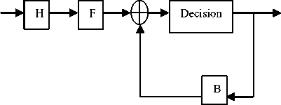
Figure 2 Brute Force Approach
As shown in Figure 2, a simplified block diagram of a DFE where the forward filter and the feedback filter can each be a linear filter . In the model considered above the input to the filter having transfer function H is y, which is matched filter [14].
v = H*y,
Then v is equalized by a feedforward filter F and a feedback filter B whereas the two filters can be calculated using the Cholesky factorization of the equivalent channel matrix S after matched filtering:
S = HH = G T G
where т is a diagonal matrix with positive elements and G is an upper triangular matrix and monic. The feedforward filter coefficient and the feedback filter coefficient is given by the expression:
F = t- 1G - 1 (18)
and
and that of the ideal MMSE-linear equalizer (MMSE-LE) is
LE min
{T b +n ' Tb N o
2 n -n / T b X(ejwTb ) + No
dw}
where we denote X ( ejwTb ) to be the folded spectrum
i.e ,
X(e jwT b
1 +^
) = V z
T b n =-^
H(w + 2n —)2 T b
Where H(w) denote the frequency response of the combined channel, the transmit and the channel filters,
Then, the output SNR y m is given by
_ 1 - J min y да .
j min
G . F lo w C h a r t fo r s im u la ti ng MIMO System with Non-Linear Receiver
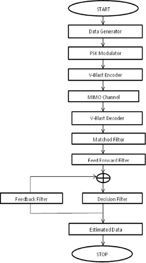
Figure 3 Flow Chart for simulating MIMO System with NonLinear Receiver
|
1090 |
-10.0 |
12900 |
-10.0 |
|
1730 |
-15.0 |
17100 |
25.2 |
|
2510 |
-20.0 |
20000 |
-16.0 |
TABLE.2 ITU channel model for outdoor to indoor and pedestrian test environment
|
Channel A |
Channel B |
||
|
Relative delays (ns) |
Average Power (dB) |
Relative delays (ns) |
Average Power (dB) |
|
0 |
0 |
0 |
0 |
|
110 |
-9.7 |
200 |
-0.9 |
|
190 |
-19.2 |
800 |
-4.9 |
|
410 |
-22.8 |
1200 |
-8 |
|
2300 |
-7.8 |
||
|
3700 |
-23.9 |
||
B. Comparison between ZF and MMSE receiver
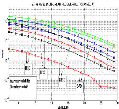
Figure.4 BER v/s SNR (Eb/No) curve for ZF and MMSE receiver in Test Channel A for different modulation order.
-
III. results
This paper deals with the performance analysis of the non-linear equalizer in vehicular channel condition. Performance has been analyzed based on MATLAB based simulation of MIMO system with linear and nonlinear equalizer.
A. Channel Characteristics
In this paper, ITU channel models for Vehicular Test Environment and outdoor to indoor and Pedestrian Test environment are considered. The channel characteristic for both the channel in term of relative delays (ns) and average power (dB) have been represented in table 1 and 2 as given below.
TABLE.1 ITU channel model for vehicular test environment
|
Channel A |
Channel B |
||
|
Relative delays (ns) |
Average Power (dB) |
Relative delays (ns) |
Average Power (dB) |
|
0 |
0 |
0 |
-2.5 |
|
310 |
-1.0 |
300 |
0 |
|
710 |
-9.0 |
8.900 |
-12.8 |
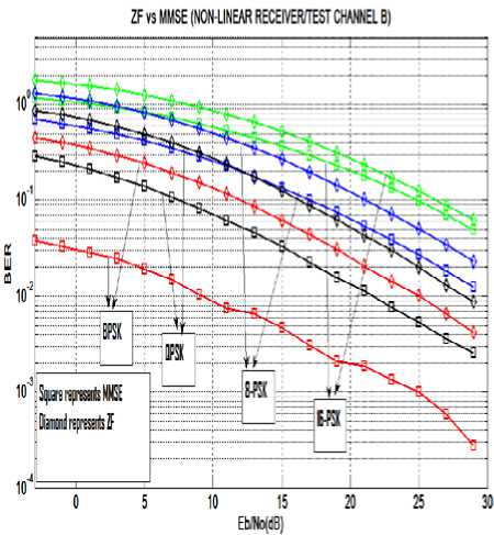
Figure.5 BER v/s SNR (Eb/No) curve for ZF and MMSE receiver in Test Channel B for different modulation order.
As shown in Figure 4 and 5 the BER v/s SNR (Eb/No) curve for ZF and MMSE receiver in a Vehicular Test Environment at different modulation order. It is observed that with the increase in SNR, the BER decreases and with the increase in modulation order, the BER increases. The BER performance of MMSE receiver is better than the ZF receiver .
As shown in Figure 6 and 7 the BER v/s SNR (Eb/No) curve for ZF and MMSE receiver in the Pedestrian Environment at different modulation order. It is observed that with the increase in SNR, the BER value decreases and with the increase in the modulation order, the BER value increases. The BER performance of MMSE receiver is better than the ZF receiver .
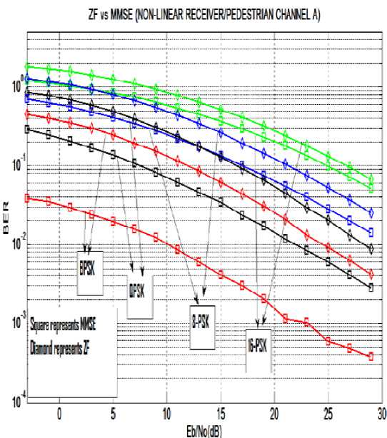
Figure.6 BER v/s SNR (Eb/No) curve for ZF and MMSE receiver in Pedestrian Channel A for different modulation
TABLE.3 ber gap between zf and mmse receiver for different modulation scheme at constant snr
|
SNR (dB) |
BER Gap |
|||
|
BPSK |
QPSK |
8-PSK |
16-PSK |
|
|
5 |
0.0596 |
0.1357 |
0.1942 |
0.2096 |
|
25 |
0.002014 |
0.006249 |
0.01379 |
0.02365 |
Table.3 shows the BER gap between ZF and MMSE receiver for a different modulation scheme at a particular SNR. It is seen that at constant SNR, BER gap increases with the increase in modulation order and with the increase in SNR, the BER gap for the same modulation scheme decreases.
C. Comparison between Linear and Non-Linear receiver
order.
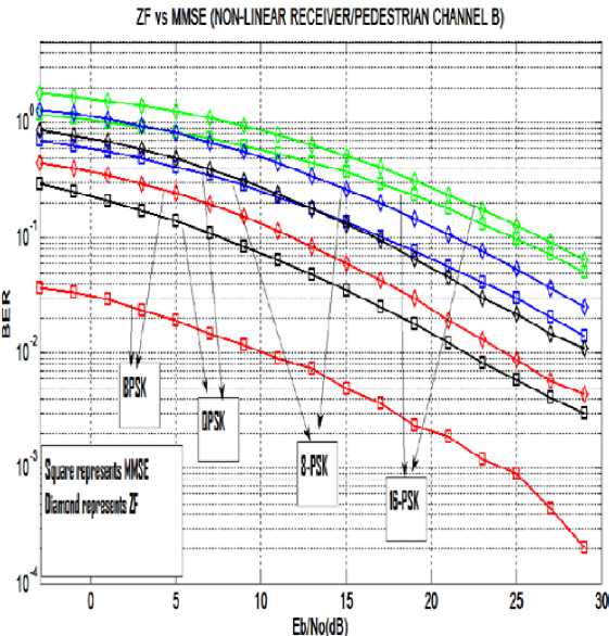
Figure.7 BER v/s SNR (Eb/No) curve for ZF and MMSE receiver in Pedestrian Channel B for different modulation
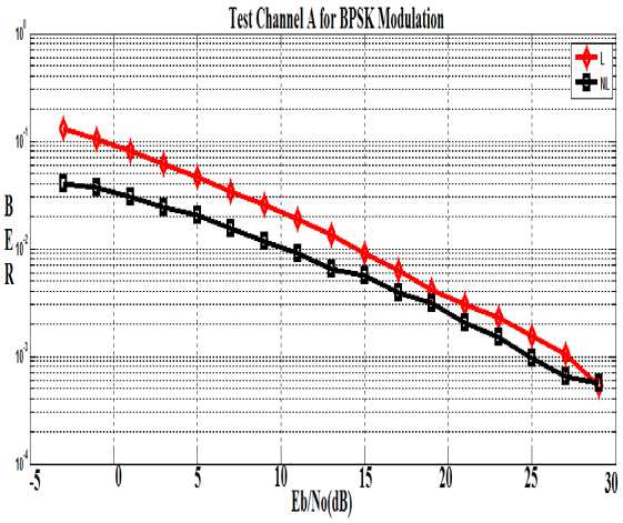
Figure.8 BER v/s SNR (Eb/No) curve for Linear (L) and NonLinear (NL) receiver in Test Channel A for BPSK modulation
TABLE. 4: BER Gap between Linear and Non-Linear receiver in Test Channel A for BPSK modulation
|
SNR(dB) |
BER |
BER Gap |
|
|
Linear |
Non Linear |
||
|
-3 |
0.1305 |
0.04016 |
0.09034 |
|
5 |
0.04678 |
0.02028 |
0.0265 |
|
25 |
0.001563 |
0.0009687 |
0.0005943 |
From the above table it is clear that as the value of SNR is increased, the BER gap between linear and nonlinear receiver decreases. In this paper we have considered MMSE-DFE as a non-linear equalizer. Thus we can conclude that at high SNR the performance of the linear and non-linear receiver converges because at high SNR the noise level is very less and the feedback path in non-linear equalizer become less significant.
order.
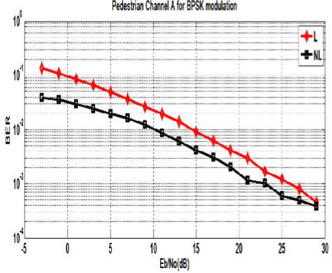
Figure.9 BER v/s SNR (Eb/No) curve for Linear (L) and NonLinear (NL) receiver in Pedestrian Channel A for BPSK modulation.
As shown in Figure 8 and 9 the comparison between linear and non-linear receiver having a fixed antenna configuration and BPSK modulation for Vehicular Test channel A and Pedestrian channel A. It is observed that as the SNR increases the BER value decreases. The BER performance of the non-linear receiver (MMSE-DFE) is better than the linear receiver (MMSE).
TABLE.5 ber gap between linear and non-linear receiver at constant snr
|
SNR (dB) |
BER Gap |
|
5 |
0.03025 |
|
25 |
0.0006247 |
Table.5 shows the BER gap between linear and nonlinear receiver for a particular SNR. It shows that as the SNR is increased the BER gap decreases. This is due to the fact that the performance on the MMSE-DFE and MMSE converges at high SNR level.
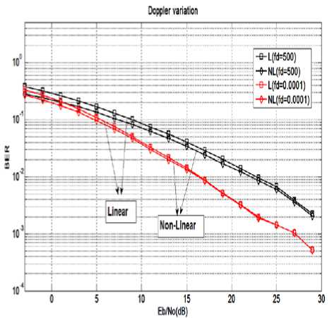
Figure.10 BER v/s SNR (Eb/No) curve for Linear (L) and Non-Linear (NL) receiver in Pedestrian Channel A for different Doppler frequency (fd).
As shown in Figure. 10 the BER v/s SNR (Eb/No) curve for linear and non-linear receiver in Pedestrian channel A at different Doppler frequency. From the above figure it is clear that as the Doppler frequency increases, BER value increases. It also shows that at high SNR the linear and non-linear receiver converges because at high SNR the noise level is very less and the basic block of Non-Linear receiver is MMSE receiver which is a Linear receiver. From the simulated result it is interesting to note that with low Doppler frequency, the performance of the linear and non-linear receiver converges at a fast rate in comparison to that of with high Doppler frequency.
-
IV. Conclusion
In this paper, the BER performance of a MIMO system with linear and non-linear receiver is analyzed. Through the simulated result one can conclude that MMSE equalizer shows a better BER performance than that of with ZF receiver. Also non-linear equalizer provides better BER performance than linear equalizer. As in simulated result, in a dynamic vehicular situation and in a very low SNR region the non-linear receiver outperforms the linear receiver and comes out as a suitable solution to deal with the vehicular environment. Based on studies and analysis one can obtain a better BER performance by implementing non-linear receiver in dynamic channel condition.
References Performance Analysis of Non-Linear Equalizer in MIMO System for Vehicular Channel
- A .J .Paulraj et al., “An overview of MIMO Communication- a key to Gigabit Wireless”, Proc. IEEE, vol. 92, no. 2, Feb. 2004, pp. 198-218.
- D. Gesbert, M.Shafi, D.S.Shiu, P. Smith, and A. Naguib, “From theory to practice: An overview of MIMO space-time coded wireless systems,” IEEE J. Select. Areaa Commun. Special Issue on MIMO System, pt. I, vol. 21, pp. 281-302, Apr. 2003.
- C.X. Wang, X. Cheng, and D.I. Laurenson, “Vehicle –to Vehicle channel modeling and measurement: Recent advances and future challenges,” IEEE Commun. Mag., vol. 47, no. 11, pp. 96-103, Nov. 2009.
- J.G. Prokis, Digital Communications, 3rd ed. New York: McGraw-Hill, 1995.
- G.J. Foschini, G.D. Golden, R.A. Valenzuela, and P.W. Wolniansky, “Simplified processing for high spectral efficiency wireless communication employing multiple-element arrays,” Wireless Pers. Commun., vol. 6, pp. 311-335, Mar. 1999.
- G. Ginis and J. M. Cioffi, “ON the relationship between V-BLAST and GDFE,” IEEE Commun. Lett., vol. 5, pp. 364-366, Sep. 2001.
- G. Bauch,”MIMO Technology for the Wireless Future,” Proc. International symposium on Personal indoor and Mobile Radio Communications, Cannes, France, Sept., 2008.
- Junqiang Shen, and Zhi Ding,”Zero-Forcing Blind Equalization Based on Subspace Estimation for Multiuser System,” IEEE Transactions on communication, vol. 49, No. 2, February 2001, pp. 262-271.
- Samarendra Nath Sur, Debjyoti Ghosh, Debasish Bhaskar and R. Bera, “Performance Analysis of V-BLAST MIMO System in Rician Channel environment,” International Journal of Computer Science and Information Technologies (IJCSIT), vol. 2 (1), 2011.
- Yi Jiang, Mahesh K. Varanasi and Jian Li, “Performance Analysis ZF and MMSE Equalizers for MIMO Systems : An In-depth Study of the High SNR Regime,” IEEE Transaction on information theory, vol. 57, no. 4, April 2011.
- P.S. Bednarz and J.M. Cioffi, “Decision feedback equalization for a channel with error correcting capabilities,” in Proc. IEEE International Conference on Communication, Montreal, Canada, 1997, pp. 1607-1612.
- N. Al-Dhahir and J.M. Cioffi,”MMSE decision feedback equalizer: Finite-Length results,” IEEE Trans. Inform, Theory, vol. 41, pp. 961-976, July 1995.
- Amit Agarwal, S. N. Sur, Arun Kumar Singh, Hemant Gurung, Abhishek Kumar Gupta and R.Bera,”Performance Analysis of Linear and Non-Linear Equalizer in Rician Channel,”, Procedia Technology 4 ( 2012 ) 687 – 691, Elsevier Ltd, 2012. doi: 10.1016/j.protcy.2012.05.11.
- Jungwon Lee, Dimitris Toumpakaris, Edward W.Jang, and Hui-Ling Lou,”DFE-based Receiver Implementation for MIMO Sysyems Employing Hybrid ARQ,” IEEE Communication Society, 2008.
- M. Stojanovic, J.G. Proakis, and J. Catipovic,”Analysis of the impact of channel estimation errors on the performance of a decision-feedback equalizer in fading multipath channels,” IEEE Trans. On Comm. , vol 43, no. 2/3/4, 877-886, Feb. /Mar./Apr. 1995.
