Performance Analysis of QoS Multicast Routing in Mobile Ad Hoc Networks Using Directional Antennas

Author: Yuan Li, Xing Luo
Journal: International Journal of Computer Network and Information Security(IJCNIS) @ijcnis
Article in issue: 2 vol.2, 2010.
Free access
In this paper, a quality of service (QoS) multicast routing protocol in mobile ad hoc networks (MANETs) by using directional antennas has been presented. Many important applications, such as audio/video conferencing, require the quality of service guarantee. Directional antenna technology provides the capability for considerable increase in spatial reuse, which increases the efficiency of communication. This paper studies TDMA-based timeslot allocation and directional antennas, and presents an effective algorithm for calculating bandwidth of a multicast tree. We also propose a novel on-demand QoS multicasting routing algorithm in TDMA-based mobile ad hoc networks using directional antennas. The simulation result shows the performance of this QoS multicast routing algorithm in TDMA-based mobile ad hoc networks using directional antennas.
Directional antennas, TDMA, QoS, multicast routing, Ad Hoc Networks
Short address: https://sciup.org/15010992
IDR: 15010992
Text of the scientific article Performance Analysis of QoS Multicast Routing in Mobile Ad Hoc Networks Using Directional Antennas
Published Online December 2010 in MECS
A mobile ad hoc network (MANET) consists of wireless nodes that communicate with each other in the absence of a fixed wireless network infrastructure. Nodes cooperate to forward data packets with each other, thus a node can communicate with another node by multi-hop. In the mobile ad hoc network, node mobility causes unpredictable topology change, the design of quality of service (QoS) routing protocol is more complicated than traditional networks. The ability to provide QoS support is dependent on how well the channel resources are managed by the protocol at the MAC layer. MAC protocols can be classified into two categories: contention-based MAC protocols and scheduled-based MAC protocols.
Recently, people have intensively studied QoS issues. QoS routing protocols proposed in [1, 2] were studied for contention-based MAC layer. The contention-based
Manuscript received March 16, 2010;
nature makes contention-based MAC protocols difficult to allocate and reserve bandwidth, which is desired by real-time multimedia application, such as audio/video conferencing.
In the schedule-based MAC protocols, each node that has been assigned a set of time slots can transmit data packets. Schedule-based MAC protocols are potentially better suited to meet QoS requirement by reserving bandwidth and following the transmission schedule. Scheduled-based MAC protocols can be classified into two categories: topology-dependent scheduling [3] and topology-transparent scheduling [4].
In the topology-dependent scheduling, each node finds conflict-free time slots by using network topology information. In the assumed Time Division Multiple Access (TDMA) model [5], the use of a time slot for a link depends on the status of its 2-hop neighboring links. TDMA-based QoS routing protocols in [6, 7, 8] take the slot assignment and interference into consideration. A stronger channel model Code Division Multiple Access (CDMA)-over-TDMA was adopted to relieve the link interference [8]. The use of a time slot on a link only depends on the status of its 1-hop neighboring links. When the bandwidth requirement is high and the network resource is rare, multi-path QoS routing protocols are developed to provide QoS support [9, 10, 11, 12].
Multicasting is a basic one-to-many communication way. A multicast group contains a special node which is responsible for transmitting data packets to the other nodes in the same group. Pushed by real-time applications with QoS requirements, a.g., audio/video conferencing and distance education, a TDMA-based QoS multicast routing protocol for wireless mobile ad hoc networks has been presented in [13].
Quality of service is more difficult to guarantee in wireless networks, especially for real-time multimedia application. There are several parameters of QoS, such as packet loss rate, delay, bandwidth etc. We focus its discussion on bandwidth, because it is one of the most critical requirements for real time application. In order to satisfy the QoS requirements of the applications, multicast protocols are required to construct multicast trees with QoS guaranteed.
In wireless networks, nodes transmit data by using an omni-directional antenna that radiates its power equally in all directions. In the above protocols, all nodes transmit data packages by using the omni-directional antenna. Directional antennas allow a node transmit data packages in a particular direction. At the same time, a receiving node can focus its antenna in a particular direction [14].
Directional antenna technology provides the following advantages [14]: (1) a smaller amount of power can be used; (2) other nodes can use the surrounding area in the other directions to transmit, which increases the spatial reuse; (3) route has shorter hops and smaller end-to-end delay. A MultiBeam Adaptive Array (MBAA) system is used in [15] and is capable of forming multiple beams for simultaneous transmissions or receptions in different directions.
This paper presents an effective algorithm for calculating the bandwidth of a multicast tree. A QoS multicast routing algorithm in TDMA-based mobile ad hoc networks using directional antennas has been proposed. When a new flow with QoS bandwidth requirement is initiated, a QoS Request (QREQ) package is flooded for determining multiple bandwidth-satisfied routes. Destination nodes collect path information from source node and send it back to source node by QoS Response (QREP) package. The source node determines the construction of a QoS multicast tree according to the path information from the destination nodes.
The rest of this paper is organized as follows: Section II describes the related works. In Section Ш, the multicast QoS routing protocol by using directional antennas is presented. The simulation results are provided in Section W . Section V concludes this paper.
-
II. Related Works
Unlike in wired networks, calculation of path bandwidth in infrastructure-less TDMA-based ad hoc networks is more difficult. The reason is that additional constraints have to be considered, such as the node mobility, limited channel bandwidth, radio interference.
The mode of operation is half duplex. This is because an antenna cannot send or receive at the same time. Radio interference problem in wireless networks must be addressed. In a frame consisting of fix number of time slots, each of which can be used by a node for sending or receiving data packets [8]. In order to address radio interference problem, a node can use a particular time slot only if the neighboring nodes which are one or two hops away do not use the same time slot [8].
For a given node, each slot is marked as either “free” or “reserved”. Where “free” means the slot is not used by the node, and is available for allocation bandwidth during the route search. “Reserved” means that the slot has been reserved for a QoS path and is not available for allocation bandwidth during the route search.

12345 12345 12345 12345 12345
(a) path
(b) slot status for five nodes

2,3,5 2,4 1,2 3,5
(c) common free slots of links
Figure 1. A path and time slot allocation
LB ( AB )=3
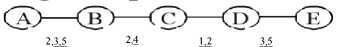
PB(ABCDE)=1
Figure 2. Slots schedule (Underline means allocated)
Consider a path and time slot allocation in Figure 1. In Fig.1 (a), suppose that there is a path from a source node A to a destination node E . Fig.1 (b) shows slot status for five nodes. The number with shadow means “reserved” slots, and other numbers without shadow mean “free” slots. Fig. 1(c) shows common free slots for links in path. Link Bandwidth ( LB ) is defined as the element number in set of slots that are marked as “free” in end nodes of a link. Such as LB ( AB ) = |Free_Slots( A ) I Free_Slots( B ) | = |{2,3,5} I {2,3,4,5} | = |{2,3,5}| =3. The link bandwidth on link ( AB ) is three slots.
Finding path bandwidth in TDMA-based ad hoc network is explained below. In Figure.2, we allocate slots {1, 2} and {3, 5} to link ( C , D ) and link ( D , E ) because there are not common free slots on continuous links. Then allocate slot {4} to link ( B , C ) because node C cannot send and receive data packages in the same slot {2} simultaneously. At last, allocate slots {3, 5} to link ( A , B ). Path bandwidth ( PB ) is defined as the minimum link bandwidth along the path. PB ( ABCDE ) = Min {2, 1, 2, 2} = 1. In other words, the bandwidth of path form the source node A to the destination node E is one slot.
There are a limited number of QoS multicasting protocols for wireless network environment. Y. S. Chen proposes a hexagonal-tree QoS multicasting protocol [16]. Ke et al. present a multi-constrained QoS-based multicast routing algorithm using the advantage of wireless network [17]. Zhao et al. have proposed a reliable multicast routing which is a multicast routing algorithm based on link quality based metric (link cost) [18]. Furthermore, Han and Guo have studied the problem of collision-free multicast in multi-channel wireless network, and presented two heuristic-based algorithms with the aim of reducing both the interface redundancy and the multicast latency [19].
Above these schemes allocate bandwidth by using omni-directional antennas. There are a limited number of bandwidth allocation schemes by using directional antennas technology. Jawhar and Wu research the resource scheduling in wireless networks using directional antennas [20]. It is assumed that a MBAA antenna is capable of broadcasting by adjusting the beam width.
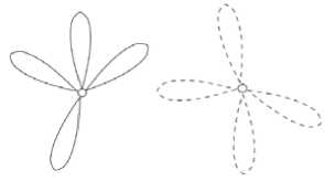
(a) Transmission mode (b) Reception mode (c) Communication mode Figure 3. Transmission pattern of antenna
B

Figure.3 shows a node equipped with a MBAA antenna array with four beams. Fig. 3 (a) shows the transmission mode of a node. Fig.3 (b) shows the reception mode of a node and Fig.3 (c) shows the communication mode from transmitter A to receiver B .
Jawhar and Wu present the slot allocation rules for directional antennas [20]. Suppose two nodes x and y are 1-hop neighbors. If node x want to transmit data to node y , node x must orient its one transmitting beam in the direction of node y and y must orient its one receiving beam in the direction of node x . A data slot t is free and can be allocated to send data from node x to neighbor y if the following conditions are satisfied:
-
1) Transmitter x don’t receive data in slot t by any antennas, and receiver y don’t send data in slot t by any antennas.
-
2) Neighbors of transmitter x don’t receive data in slot t , from x where neighbors is in the same angular direction as receiver y .
-
3) Neighbors of receiver y don’t send data in slot t , from y where neighbors are in the same direction as transmitter x .
-
III. Definition and Suppossion
In this paper, we represent a static multi-hop wireless network with an undirected network graph G ( V , L ). Where V represents the set of nodes and L represents the set of links between the nodes. In wireless networks, we suppose that the interference range ( R I ) between two nodes is twice of the transmission range ( R T ) of node. i.e., R I =2 x R T .
Suppose there are a source node S and a set of destination nodes R . Our purpose is to find a set T in which connect the source node S with each destination node r i e R (1 < i < m ), and paths found from S to r i can satisfy the quality of service requirement of the application. Given a multicast tree t e T , l ( v i , v j ) e t is a link in multicast tree t ( v i e V , v j e V) , we give the following definitions.
Definition 1:
The bandwidth of a multicast tree is defined as the minimum path bandwidth in the tree.
bandwidth (T) = Min{path bandwidthi} (1 < i < m) (1)
Definition 2:
The delay of a multicast tree is defined as the maximum path delay in the tree.
delay ( T ) = Max{ £ delay (A)} (2)
l i e PATHs
Definition 3:
The network cost of a multicast tree is defined as the total cost of all the paths in the tree.
cost( T ) = cos t ( Path i ) (3)
i = 1
Definition 4:
The cost of a multicast tree is the consumed network resource in all paths. The consumed network resource in a path is defined as the reserved path bandwidth times the hop number in the path.
cost(Pathi)= path bandwidthix hop number (Pathi) (4)
Based on the above definitions, the problem of satisfying the quality of service requirement can be formulated as follows. Given a graph G ( V , L ), our work is to find a tree T such that the following three conditions are satisfied. Where B is the minimum bandwidth requirement of the application, D is the maximum delay requirement of the application, and C is the maximum cost requirement of the application.
bandwidthT) ^ B(5)
delay(T) < D(6)
cost(T) < C(7)
Definition 5:
The bandwidth of link l in a multicast tree is the sum of the path bandwidths of the current connections that use this link l .
bandwidth( l ) = ^ bandwidth (8)
l c Path i
Definition 6:
If the path is interference-free scheduled, then any three consecutive links on a path are not assigned same time slots. For any slot t , any interference-free link scheduling must satisfy the following condition. Where l 1 , l 2 and l 3 are three consecutive links in a path. T ( l i , t ) denotes whether the link l i use slot t to transmit data packages.
T (11, t) + T (12, t) + T (13, t) < 1 (9)
-
IV. QoS Multicast Routing Protocol
A. Data Structures
In wireless networks, let each node x maintains three tables: send table ( ST ), receive table ( RT ) and hop-count matrix ( H ).
The send table of node x (ie., STx [i, j]) contains slot status for the 1-hop or 2-hop neighbor i of node x for sending data. If slot j of node i has been reserved for sending data, then STx [i, j] = 1; If slot j has been allocated for sending data, STx [i, j] = 0; Otherwise, slot j of node i is free and STx [i, j] = -1.
The receive table of node x (ie., RT x [ i , j ]) contains slot status for the 1-hop or 2-hop neighbor i of node x for receiving data. If slot j of node i has been reserved for receiving data, then RT x [ i , j ] = 1; If slot j has been allocated for receiving data, RT x [ i , j ] = 0; Otherwise, slot j of node i is free and RT x [ i , j ] = -1.
The hop-count matrix Hx [ i , j ] contains neighborhood information about the 1-hop and 2-hop neighbor i of node x . If node i has node j as a neighbor, then H x [ i , j ] = 1; Otherwise, H x [ i , j ] = 0.
The above three tables also contain angular groups field. The entry A[ a ] i j denotes the set of angular groups to which the a th sending/receiving antenna is pointed. A[ a ] i j =null indicates that the a th antenna for node i is not used during slot j .
B. QoS multicast routing by directional antennas
Our QoS multicast routing protocol by directional antennas requires finding routes satisfing QoS requirement from a source node to a group of destination nodes. Suppose that each node is equipped with a MBAA antenna array with four beams.
When a source node S wants to send data to a group of destination nodes with a bandwidth requirement of b slots and maximal delay bound D , it broadcasts a QREQ ( S , Destination_Set , id , b , D , x , PATH , NH , TTL ) package to all 1-hop neighbors. The QREQ package contains the following fields.
-
(1) S is a source node;
-
(2) Destination_Set is a set of destination nodes;
-
(3) id is identity of request;
-
(4) b is the bandwidth requirement;
-
(5) D is the maximal delay requirement;
-
(6) x is a node currently relaying the QREQ.
-
(7) PATH is path together with the available slots that has been discovered.
-
(8) NH is a list of next-hop nodes of node x , together with the format (( h’ 1 , l’ 1 ), ( h’ 2 , l’ 2 )… ( h’ n , l’ n )). Where h’i has potential to serve as the next hop of node x , along with a list of slot l’ i . Node x may transmit data to neighbor h’ i by using slots in l’ i .
-
(9) TTL is the delay bound which is equal to D .
Figure.4 shows the process of dealing with QREQ package. When an intermediate node y receives a QREQ package from 1-hop neighbor node x , it will decide whether QREQ has been received according to S and id . If yes, it will drop this QREQ package to avoid loop path. If node y has been in PATH , it will drop the RREQ. If node y is not a node in NH , it drops the RREQ. If value of TTL is 0, it drops the RREQ package. Otherwise, it will reduce TTL by 1, adds itself into PATH , and adds its free time slots into PATH .
Node y creates temporary send table (STtemp) and temporary receive table (RTtemp). Then copy all entries in STy into STtemp, and copy all entries in RTy into RTtemp. Assign STtemp[hj, t] = STtemp[hj+1, t] =0 for each slot t in the list li (i=m, m+1). In order to avoid hidden terminal problem, the same slot can’t be allocated to three consecutive links (i.e., lm, lm+1, l’temp). Let NHtemp=null at first.
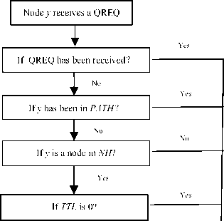
No
TTL -1; add itself into PATH;
Create ST temp , RT temp and NH temp ; Broadcast the new QREQ;
Figure 4. The process of dealing with QREQ package
Drops RREQ
For every 1-hop neighbor node z of node y , do L = select_slot ( y , z , b , ST temp , RT temp ). The procedure select_slot ( y , z , b , ST temp , RT temp ) denotes find b free slots from link ( y , z ) according to the ST temp and RT temp . If L is not null, then NH temp =NH temp |( z , L ).
If L is null, then discards this QREQ. The reason is that node y cannot find one neighbor to extend next hop such that link bandwidth can satisfy the bandwidth requirement b of the application. It mainly relies on slot allocation rules for directional antennas to do the selection.
If the following three conditions hold, slot t is an available slot that can be allocated to the link ( y , z ). Where A y w ∧ A y z ≠ Φ denotes that 1-hop neighbor w of node y is in the same direction as z from node y .
Condition 1: (RTtemp[y, t]=-1) ∧(STtemp[z, t]=-1)
This condition shows that node y does not receive data in slot t by any antennas, and 1-hop neighbor z does not send data in slot t by any antennas.
Condition2: (Hy[y, w]=1) (RTtemp[w, t]=-1) ∧(Ayw ∧Ayz ≠Φ)
This condition implies that 1-hop neighbor node w of node y does not receive data in slot t , from node y where 1-hop neighbor node w is in the same angular direction as node z .
Condition 3: (Hy[z, w]=1) ∧(STtemp[w, t]=-1) ∧(Azw∧ Azy≠Φ)
This condition expresses that 1-hop neighbor node w of node z does not send data in slot t, from node z where 1- hop neighbor node w is in the same angular direction as node y.
When finishing the above steps, a new QREQ package will be rebroadcasted and the status of selected slots will be changed from free to allocated if the NH temp is not null. When the QREQ package is forwarded from the source node S , it can be regarded as a special case of intermediate nodes. The above steps are performed by replacing y with S , and PATH and NH are null at first.
When a destination node D i ( D i e DestinationSet ) receives the first QREQ, a path p 1 has been formed. The path bandwidth is the minimum number of available slots of links in PATH . In other words, the path bandwidth is the number of slots in l narrow (i.e., b i =| l narrow |). l narrow is the bandwidth of the narrowest link. The destination node D i sends a QREP( S , Di , id , bi , PATH ) package along the reverse PATH . Every intermediate nodes along PATH will reserve b i slots.
When the source node S receives all QREP packages from the destination nodes in Destination_Set , it computes the available bandwidth and the delay of a multicast tree.
If the following two conditions are satisfied, the source node S will find a QoS multicast tree. Where delay ( l i ) expresses the hop-count of the i th route, and D expresses the maximal delay and b is the bandwidth requirement of the application.
Min { b i } > b (10)
Max { £ delay (ф < D (11)
l i e PATHs
-
V. Simulation
In this section, a simulation study is performed by using ns 2 to evaluate the performance of our protocol. Suppose 50 nodes randomly placed in 1500m x 300m area. Every connection requests is generated with a randomly chosen source-destinations set pair. The number of date slots in a frame is 32. The data rate of a slot is 512Kbps. The maximal speed of node is 1m/s. The number of source node is 1. Suppose that the transmission range of wireless nodes is 250 meters and the interference range between wireless nodes is 500 meters.
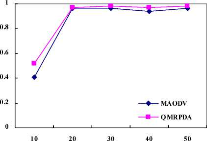
Fig 5 shows the packet delivery ratio under different network environment for our QoS multicast routing protocol with directional antennas and other routing protocols. Our proposed QoS multicast routing protocol with directional antennas is labeled as QMRPDA. MAODV protocol and AODV protocol are compared with our protocol. Assume that the number of directional antennas is four.
In Fig 5, it can be seen that when the number of destination nodes increases, QMRPDA and MAODV will have higher packet delivery ratio. Except that the number of destination nodes is 10, the packet delivery ratio of two multicast protocol is above 97% and 94%. As the number of destination nodes increases, QMRPDA will gradually ourperform MAODV.
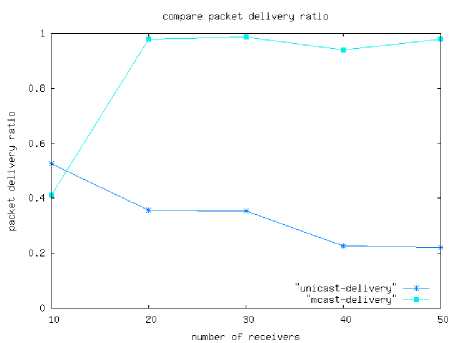
(a) Packet delivery ratio of AODV and MAODV
number of receivers
(b) Packet delivery ratio of QMRPDA and MAODV
Figure 5. Packet delivery ratio under different network environment
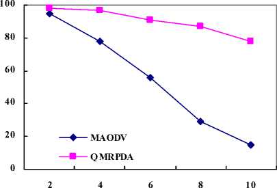
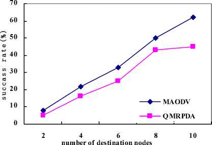
Fig. 6 shows the call success rate under different network environment for our QoS multicast routing protocol with directional antennas and MAODV. When the number of destination nodes is very small or bandwidth requirement is very low, MAODV will almost have the same call success rate with our QoS multicast routing protocol. However, as the number of destination nodes or bandwidth requirement increases, the call success rate of the QMRPDA will gradually out perform the MAODV.
In Fig. 6(a), when the bandwidth requirement increases, the call success rate of QMRPDA will range from 97% to 78%. MAODV will be blocked. In Fig. 6(b), when the number of destination nodes increases, interference between links will increase. QMRPDA alleviates the interference between links by using directional antennas.
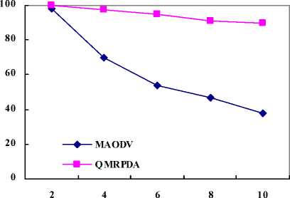
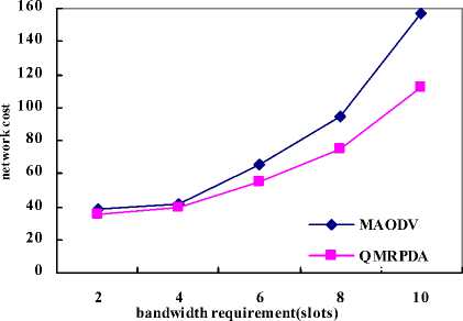
Fig.7 shows the network cost under different network environment for our QoS multicast routing protocol with directional antennas and MAODV. When the number of destination nodes is very small or bandwidth requirement is very low, MAODV will almost have the same network cost with our QoS multicast routing protocol with four antennas. In Fig. 7(a), when the bandwidth requirement increases, the network cost of MAODV is higher than the cost of QMRPDA.
bandwidth requirement(slots)
(a) The call success rate under different bandwidth requirements
number of destination nodes
-
(b) The network cost under different number of destinations Figure 7. Network cost under different network enviroment
In Fig. 7(b), when the number of destination nodes increases, interference between links will increase. The available bandwidth on links will decrease. Though MAODV protocol selects a multicast tree with small network cost, but these paths may not meet the bandwidth requirement, thus MAODV has the higher network cost than QMRPDA protocol.
-
VI. Conclusion
In this paper, we propose a novel QoS multicast routing protocol in TDMA-based mobile ad hoc networks using directional antennas. The source node tries to discover a multicast tree that is capable of providing the desired QoS requirement. The slot allocation and reservation procedure use the local topology information. The protocol takes advantage of the significant increase in spatial reuse provided by the directional antenna environment. The simulation results clearly show that compared with MAODV, our approach can obtain better performance in terms of the packet delivery ratio, call success rate and network cost.
(b) The call success rate under different number of destinations Figure 6. The call success rate under different network environments
Acknowledgment
This work has been supported by The Young and Middle-aged Elitists’ Scientific and Technological Innovation Team Project of the Institutions of Higher Education in Hubei Province (No. 200902), Key Scientific Research Project of Hubei Education Department (No. B20091904).
(a) The network cost under different bandwidth requirements
References Performance Analysis of QoS Multicast Routing in Mobile Ad Hoc Networks Using Directional Antennas
- L. Chen and W. B. Heinzelman, “QoS-aware Routing Based on Bandwidth Estimation for Mobile Ad Hoc Networks,” IEEE J. Selected Areas in Comm., vol. 23, pp. 561-572, 2005.
- Z. Jia, R. Gupta, J. Walrand, and P. Varaiya, “Bandwidth Guaranteed Routing for Ad-Hoc Networks with Interference Consideration,” Proc. IEEE Symp. Computer and Comm (ISCC’05), pp3-9, 2005.
- A. Ephremides and T. V. Truong, “Scheduing Broadcast in multihop radio networks,” IEEE Trans on Commun, 38(4):456-460, Apri, 1990.
- Y. S. Su, S. L. Su, and J. S. Li, “Joint Topology-Transparent Scheduling and QoS Routing in Mobile Ad Hoc Network7s,” IEEE Intel. Conf. On Networding, Architecture, and Storage, pp. 70-77, 2008.
- C. Zhu and M. S. Corson, “QoS Routing for Mobile Ad Hoc Networks,” Proc. INFOCOM’02, pp. 958-967, 2002.
- W. H. Liao, Y. C. Tswng, and K. P. Shih, “A TDMA-based Bandwidth Re-servation Protocol for QoS Routing in a wireless Mobile Ad Hoc Network,” Proc. IEEE Int’l Conf.Comm.(ICC’02), pp.3186-3190, 2002.
- K. P. Shih, C. Y. Chang, Y. D. Chen, and T. H. Chuang, “Dyanmic Bandwidth Allocation for QoS Routing in TDMA-based Mobile Ad Hoc Networks,” Computer Comm., vol.29, pp.1316-1329, 2006.
- C. R. Lin and J. S. Liu, “QoS routing in Ad Hoc Wireless Networks,” IEEE J. Selected Areas in Comm., vol. 17, pp. 1426-1438, 1999.
- Y. S. Chen, Y. C. Tseng, J. P. Sheu, and P. H. Kou, “An On-Demand, Link-State, Multi-Path QoS Routing,” Computer Comm., vol. 27, pp.27-40, 2004.
- Y. S. Chen and Y. T. Yu, “Spiral-Multipath QoS Routing in a Wireless Mobile Ad Hoc Network,” ICICE Trans on Commun, pp. 104-116, 2004.
- W. H. Liao, Y. C. Tswng, J. P. Sheu, “A Multi-path QoS Routing Protocol in a Wireless Mobile Ad Hoc Network,” IEEE Intel. Conf. on Networking, pp. 158-167, 2001.
- Y. S. Chen, S. J. Jan, and M. C. Chuang, “A Shoelace-Based QoS Routing for Mobile Ad Hoc Using Directional Antenna,” IEEE TENCON 2007, pp. 1-4, 2007.
- Y. S. Chen, T. H. Lin, and Y. W. Lin, “A hexagonal-tree TDMA-based QoS multicasting protocol for wireless mobile ad hoc networks,” Telecommunication Systems, vol. 35, pp.1-20, 2007
- I. Jawhar and J. Wu, “Resource Scheduling in Wireless Networks Using Directional Antennas,” IEEE Transactions on Parallel and Distributed Systems, vol. 21, pp. 1240-1253, 2010.
- L. Bao and J. J. Garcia-Luna-Aceves, “Transmission Scheduling in Ad Hoc Networks with Directional Antennas,” Proc. Eighth Ann.Int’l Conf. Mobile Computing and Networking, pp. 48-58, Sept, 2002.
- Y. S. Chen, T. H. Lin and Y. W. Lin, “A hexagonal-tree TDMA-based QoS multicasting protocol for wireless mobile ad hoc networks,” Telecommunication Systems, vol. 35, pp.1-20, 2007.
- Ke Z, Li L, Sun Q and Chen N, “A QoS multicast routing algorithm for wireless mesh networks,” Proc. Eighth Int’l Conf.Software Engineering, Artifical Intelligence, Networding, and Parallel/Distributed Computing, vol. 1pp. 835-840, 2007.
- Zhao L, Al Dubai A and Min G, “A QoS aware multicast algorithm for wireless mesh networks,” Proc. Int’l Symposium on Parallel and Distributed Processing, pp. 1-8, 2009.
- Han K and Guo Q, “Reducing multicast redundancy and latency in wireless mesh networks,” Proc. First Int’l Workshop on Education Technology and Computer Science, vol. 1, pp. 1075-1079, 2009.
- I. Jawhar and J. Wu, “Resource Scheduling in Wireless Networks Using Directional Antennas,” IEEE Transactions on Parallel and Distributed Systems, vol. 21, pp. 1240-1253, 2010
