Performance Analysis of Rectangular and circular Shape Building Deployment for an Indoor Visible Light Communication System

Author: Ram Sharma, A. Charan Kumari
Journal: International Journal of Computer Network and Information Security(IJCNIS) @ijcnis
Article in issue: 7 vol.9, 2017.
Free access
The LED (Light emitting diode) based lighting systems are gaining popularity for its dual use i.e. for energy efficient lighting systems as well as for indoor optical wireless communication systems. Although, Visible light spectrum has the capability to provide very large system bandwidth (in THz), yet these systems have the limitation on account of limited modulation bandwidth. Besides, Visible light communication (VLC) systems also suffer due to multi-path propagation resulting in further depletion of system bandwidth due to pulse broadening. Therefore, one of the deployment objective of a visible light communication (VLC) system is to reduce the root mean square (RMS) delay parameter besides minimizing the number of LEDs. Hence, performance analysis of two geometrical shape structures mainly rectangular and circular models are explored for ubiquitous indoor coverage using hyper- heuristics evolutionary algorithm(HypEA) under spatial receiver mobility. Therefore, it is possible to achieve lower RMS delay spread and hence multi- fold increase in the overall system bandwidth without the use of complex system techniques like OFDM- MIMO etc.
Average outage area ratio, hyper-heuristic evolutionary algorithm, indoor VLC system, root mean square delay, Signal to Noise Ratio
Short address: https://sciup.org/15011862
IDR: 15011862
Text of the scientific article Performance Analysis of Rectangular and circular Shape Building Deployment for an Indoor Visible Light Communication System
Published Online July 2017 in MECS
Light emitting diodes (LEDs) are energy efficient, comparatively low cost and eco-friendly devices which are being used extensively for lighting systems in the indoor environment. LEDs have seen phenomenal growth in terms of technology enhancement resulting in increased life span, high intensity and low power which makes it very useful for indoor Visible light communication (VLC)system. Among various types of LEDs including PC-LEDs (Phosphorous converted LEDs), organic LEDs, micro-chip LEDs (µ- LEDs), multichip LEDs, the 3 dB bandwidth of micro chip LEDs may go up to 450 MHz [1]- [2]. Thus, the use of fast switching, high illumination white LEDs are likely to enhance the performance of a VLC system in terms of bandwidth parameters. Over the last few decades, a qualitative progress has been witnessed towards innovating new wireless technologies. This also reflects the ever rising demand for voice, data and various other multimedia services with guaranteed quality of service parameters (QOS) which are putting additional pressure on the existing spectrum which is a scarce resource. The Next Generation Wireless Network (NGWN) especially the indoor networks will have to be evolved with very high data rates[3].
Presently, the demand for mobile and data services in the indoor communication domain is increasing exponentially due to various multimedia applications. The recent studies indicate that a substantial portion (more than 70 percent) of wireless traffic originates indoors. This is usually catered through radio femtocells which are low-power, low-cost base stations (BSs). These cellular base stations are overlaid on the existing cellular network and are generally user deployed. The femtocells improve the indoor capacity as well as the coverage mainly due to the frequency reuse within the range of tens of meters[4]. An alternative solution to radio frequency (RF) technique is VLC technology which has the potential of delivering greater data rate densities ( b/s/Hz/m 2)[5]. The main attraction of VLC technology is its spectrum which is available for free and is presently unregulated. Besides VLC can be used inside airplanes, hospitals, factories, mines, power plants, petrochemical plants etc where the use of RF technology is prohibited. Since lighting is an essential requirement for indoor illumination, therefore, no extra energy is required for information transmission except for a minimal additional power requirement for the driver circuitry for communication. In this way, VLC is also capable of reducing the carbon footprint in the information and communication technology (ICT) industry resulting in the energy efficient networks[6].
This may also be stated that vast unused spectrum may provide the necessary bandwidth to meet the evergrowing demand for increased telecommunication traffic.
VLC can further help in establishing more secure networks. There remain, of course, many challenges that VLC systems are currently facing due to being a relatively new technology. There are issues that remain from the inherent nonlinearity of LEDs, bandwidth limitations, signal modulation aspects, multi-access as well as power delivery to the transceiver. However, since such technical challenges have already been overcome in RF technique after decades of research, Similarly, VLC is well poised to go along a similar but much-accelerated path. Hence there is no doubt that VLC will be able to provide ubiquitous communication network in future communication generations[7].
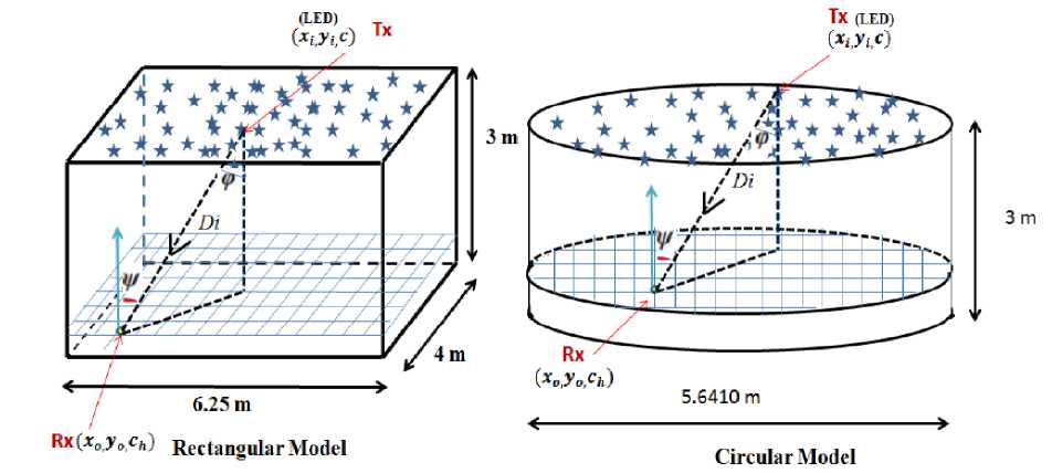
Fig.1. Proposed system Models
The VLC communication system may employ various link topologies depending on the transmitters beam directionality and receivers field of view (FOV). For a mobile VLC system, the nondirected-LOS first proposed by [8]. For indoor VLC systems, the genetic evolutionary algorithm was first implemented by [9]- [10] to modify the optical intensity to analyze the signal to noise ratio (SNR) fluctuations. Further Particle swarm optimization (PSO) technique was used for LED deployment by [11]. One of the most important advantages of a VLC system is its bandwidth reuse so as to achieve high spatial spectral efficiency. The LEDs are capable of providing highly directional beams which make it possible to transmit the signal with lesser interference. Therefore, non-interfering links in close proximity could make it possible to achieve large data density [12] and spatial reuse of modulation bandwidth in adjacent communication cells [13]-[14]. An adaptive receiver technique has been suggested by [15] to address a number of challenges posed by LED-based indoor communication system especially the signal distortion due to multipath propagation which limits the system's bandwidth. Further, an Electro-optic Modulators for low loss wide bandwidth capability for optical communication system has been discussed by [16] including the optimization of a number of system parameters. An IR-based mobile system comprising a single IR source and a mobile receiver based on nondirected-LOS diffused topology was investigated for its system performance by[17] followed by its channel capacity and BER estimation along with detailed analysis of various other system parameters by[18].
In literature, a different heuristic technique known as hyper-heuristic evolutionary algorithm (HypEA) have been suggested by [19] for dynamic assignment of radio frequency channels. The HypEA approach [20] is presented in Appendix A. Motivated by this approach and the computing efficiency of the algorithm, we propose to implement HypEA technique to the proposed VLC problem for two types of system models. System model 1 is proposed to be a rectangular room and system model 2 is consisting of a circular room. The LEDs are placed on the rooftop. The system performance is analyzed and compared after the HypEA implementation for the two system models to ensure receiver mobility mainly with the following contributions,
-
• We analyze the average outage area ratio defined as the average outage area ratio as the area where the receiver detects an error during its movement to the total floor area of the room. A comparison is thus made for the optimum deployment of LEDs for both the models.
-
• The impact of LED semi-angle on the receiver mobility has been analyzed along with the number of LEDs required at various semi-angle of LEDs.
-
• The root mean square (RMS) delay is analyzed to assess the inter-symbol interference (ISI). RMS delay at various semi-angle has also been analyzed. It has been demonstrated that more
directionality improves the RMS delay and hence the ISI is reduced.
The rest of this paper is organized as follows. The related work is presented in section II and the system model in section III. The problem is formulated in section IV. The results are analyzed in section V. Finally, the conclusion is given in section VI.
-
II. Related Work
4G/5G Indoor VLC (380 – 780 nm) can be considered as a relatively new technology proposed as an alternative to indoor IR (780-950 nm) access technologies[21,22] offering a number of functionalities. In addition to illumination, VLC offers data communication and indoor localization (where current RF based global positioning systems (GPS) offers limited or no coverage in the indoor and underground environment using the existing white light emitting diodes (LED) based lighting fixtures[23]. These features have made the emerging field of indoor short-range VLCs very attractive to the worldwide research community, through bodies such as the VLC consortium (more than 20 organizations) in Japan in 2003 [24], the Wireless World Research Forum[14], the European OMEGA project [25], IEEE standardization body [26, 27], and UK research council funded ultraparallel VLC [28].
The current IEEE VLC standard approved in 2011 supports up to 96 Mbps. A Task Group recently revived the work in IEEE 802.15.7 and is working on an enhanced VLC physical layer based on OFDM to enable peak data rates at Gbps. It is also planned that this standard will support optical camera communication (OCC) where Smartphone cameras are used for reception in low data rate applications[29]. Standardization is expected to be finalized by the end of 2017. With the emergence of Indium Gallium Nitride (InGaN) technology it has been possible to manufacture efficient white LEDs in a number ways: (a) combining red, green, blue light sources (RGB) offer typically 20 MHz of Existing off-the-shelf LEDs have a limited bandwidth (up to 50 MHz for incoherent IR, <10 MHz for WPLED and 400 kHz for organic LEDs). Using commercial high power LEDs, VLC systems can provide 200+ Mbps data rates. In VLCs the most popular way to increase the system bandwidth is to use a blue filter and adopt spectrally efficient modulation schemes such as DMT and orthogonal frequency division multiplexing (OFDM) [30]. A data rate of 230 Mb/s was reported in [31], which uses a bandwidth of 30 MHz with the nonreturn to zero (NRZ) on-off keying (OOK) data format and an avalanche Photo-detector.
-
III. System Model
Each system model considers an indoor room having an area dimension 6 . 25 m x 4 m for rectangular whereas the circular shape possesses a radius of 2.8205 in meters.
Both the models thus represent the same area i.e. 25 square meters. The height of the structures is considered as 3 meters for these models. Also, the receiver is mobile on the x-y plane whose location is given as (xo, yo, ch). It is proposed to deploy N LEDs on the roof/ceiling at positions (xi, yi, c), where c = 3 meters and i ∈ (1, 2, 3, ....N ). For rectangular shape, the placement coordinates of LEDs are bound by the dimension such that 0 < xi < 6.25 and 0 < yi < 4 . Accordingly, LED positioning in the circular shape is bound within the desired circle boundary of requisite radius as given above.
Among all the modulation techniques based on intensity modulation with direct detection (IM/DD), on-off keying (OOK) is the most appropriate, simple and widely accepted modulation scheme used in optical wireless communication (OWC) system because of its ease of hardware implementation, simple receiver design, bandwidth efficiency and cost- effectiveness [32].
Table 1. Comparison of Average Outage Area Ratio ’R’ and the Number of LEDs at semi- angle ( ϕ 1 / 2 = 60 o )
|
Sl. No. |
No. of LEDs |
Value of 'R' (Rectangular Model) |
Value of 'R' (circular Model) |
|
1 |
10 |
1.0000 |
1.0000 |
|
2 |
20 |
1.0000 |
1.0000 |
|
3 |
30 |
1.0000 |
1.0000 |
|
4 |
40 |
0.7684 |
1.0000 |
|
5 |
50 |
0.6692 |
1.0000 |
|
6 |
60 |
0.5616 |
1.0000 |
|
7 |
70 |
0.4447 |
0.5246 |
|
8 |
80 |
0.3089 |
0.4453 |
|
9 |
90 |
0.1756 |
0.3768 |
|
10 |
100 |
0.0576 |
0.2571 |
|
11 |
110 |
0.0066 |
0.0000 |
|
12 |
120 |
0.0000 |
0.0000 |
The binary information sequence can be mapped directly to the sequence of light pulses at the transmitter according to the rule: if the information bit is 1, transmit a laser pulse; if it is 0, transmit nothing , Therefore, there is a one-to-one correspondence between 1’s in the datastream, and the occurrence of light pulses emanating from the transmitter. The OOK modulation format is proposed for our system investigation accordingly. The modulated bit stream using intensity modulation/ direct detection (IM/DD) is therefore transmitted into the free space medium and is received at PN/PIN photodetector receiver. The receiver is placed at a height, z = ch = 0.85 meters on the x-y plane above the ground level. The receiver current, Y (i), is expressed as Y (i) = ζ X(i)* h(i) + η, where ζ represents the responsivity of the photo detector in A/W, X(i) is the transmitted optical signal which is nonnegative i.e. X(i) ≥ 0, h(i) denotes the channel impulse response and η is the additive white Gaussian noise (AWGN) with zero mean and variance σ2. The channel impulse response h(i) between the ith LED and the receiver is given as in [33] as
1 ^ - y
Q ( x ) = -;={ exp 2 dy (8)
V 2 п x
h ( i ) =-
( m + 1)2 A cos m (Ф) T s (V)g(V) cos(V ), if 0 < V < V 2П D i c
0,
ifV ^ Vc
where, n , denotes the order of Lambertian emission and is expressed in terms of semi-angle ( ϕ 1 / 2 ) at halfilluminance of a LED as, m = ln 2 / ln cos( ϕ 1 / 2), A is the area of the photodetector receiver, D i is the distance between a LED and a receiver, is the angle of incidence, ф denotes the angle of irradiance and T(ф ) presents the gain of the optical filter. The gain of an optical concentrator is denoted by g (ф ) whereas the receiver’s field of view is expressed as ф c . The optical concentrator’s gain, g (ф ), is given as,
Since the receiver is uniformly distributed on the x-y plane at z = ch , let its probability distribution function (pdf) be defined by the function f ( xo, yo ). The average outage area ratio, R , is now defined by [12] as the ratio of the average outage area where the BER is greater than the threshold level, Pth , to the total receiver plane area, Stotal such that,
E [ ^ ( P ber ( x , y ) > P th )]
S Total
R = U S ( P ber ( x , y ) > P th ) f ( xo . yo ) dxodyo 00
S Total
g (V ) = -
P
sin 2 ( V c )
0,
If 0 < V < Vc ifV ^ Vc
where µ denotes the refractive index. By using the Cartesian coordinate system, cos(ϕ) can be expressed as cos(^) =-------------c—ch------------f (3)
[( c - c h ) 2 + ( X 0 - x i ) 2 + ( y 0 - y i ) 2 ] 2
Further, It can be expressed that cos (ф)= cos( ф ). Since Ts (ф ) =Ts and g (ф ) =g , the expression (1) can be written as
. TsgA ( C - Ch ) m+1„'
hi =--------------------------------------m+г
2 n 2[( c - C h ) 2 + ( X 0 — X i ) 2 + ( y 0 - y i ) 2 ] 2
The received power at the detector due to all the LEDs can thus be expressed as
Pr = jNPthi(5)
i = 1
where p ti is the transmitted power of the ith LED. Accordingly, the electrical SNR, γ , can be given as
, = ZPPL cr
For the OOK modulation scheme, the bit error rate can be expressed as in [34] as
Pber = Q()
The threshold value, Pth , has been considered as 10 - 6 as per available literature [5].
The RMS delay is a good measure to understand the ISI caused due to the spread of the LEDs. The mean delay and RMS delay of the impulse response is measured as,
u z N 1 t i h^ t )
Z N 1 h 2 ( t )
and,
T rms =
I z N 1 ( t i - p ) h"( t )
V z N h 2 ( t )
where ц and t r ms denote the mean delay and RMS delay respectively. The t , denotes the transmission delay due to ith LED and hd denotes the impulse response due to i tR LED.
IV. Problem Formulation
The proposed VLC system is expected to perform with zero average outage area ratio, ’R’, within indoor room scenario under receiver mobility. So a requisite amount of SNR level is to be maintained throughout the indoor room environment. The average outage area ratio, R , thus depends upon the number of LEDs which are distributed within indoor room involving the different type of structures along with their positions. So the main objective is to obtain the zero outage area ratio through optimization of the LED positions as well as involving semi- angle.
where,
Table 2. Comparison of average outage area ratio ’R’ and the number of LEDs at various semi-angle values
|
Semi Angle (Degrees). |
No. of LEDs (Rectangular) |
No. of LEDs (Circular) |
Value of 'R' |
|
2.5 |
530 |
140 |
0.00 |
|
5 |
170 |
40 |
0.00 |
|
7.5 |
110 |
40 |
0.00 |
|
10 |
80 |
40 |
0.00 |
|
15 |
68 |
50 |
0.00 |
|
20 |
70 |
50 |
0.00 |
|
30 |
75 |
70 |
0.00 |
|
40 |
90 |
85 |
0.00 |
|
50 |
100 |
100 |
0.00 |
|
60 |
120 |
110 |
0.00 |
|
70 |
130 |
125 |
0.00 |
|
80 |
140 |
135 |
0.00 |
Let the LED location is described as (x,y) and correspondingly the vector x = (x1, x2, x3, xN) and vector, y = (y1, y2, y3, ....... yN) represents x and the y positions for N LEDs. Hence the problem statement for the LED deployment would be as, min(x,y) [R]
This is subject to, 0 < xi < a, i ∈ (1 , 2 , 3, ......N) and 0
< yi < b, i = (1 , 2 , 3 , ......N) where a and b are the length and the breadth of the room. In order to compute the average outage area ratio, R , as per the definition in (9).
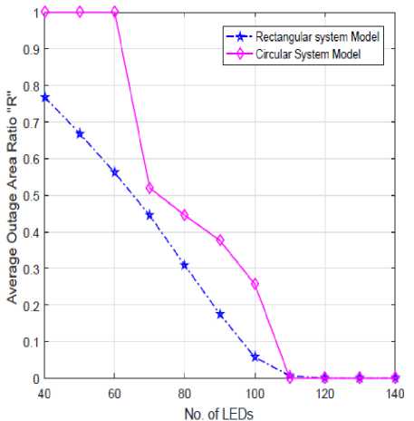
Fig.2. Average Outage Area Ratio vs. No. of LEDs the receiver plane has been divided into L number of regular grids with respect to x and y-axis. Therefore the objective function for obtaining, R, is depicted as,
L
where P l is defined as the probability that a receiver is placed in the l th grid and its corresponding BER is expressed as P l BER ( x, y ). Since the receiver distribution is considered as uniform distribution, therefore the probability that a receiver lies in l th grid would be given as Pl = 1/ L, Also, the function U (Ω) is defined as,
[ 1, a> 0 и ( ^ ) = ’ (14)
[ 0, ^< 0
Thus, a problem formulation is done to implement the LED placement within the defined search space for the optimal location of LEDs as per the figure 1. Further, the variation of LED semi-angle is analyzed for the requirement of number of LEDs for receiver mobility. Thus, a total of N LEDs are distributed optimally using HypEA search technique.
-
V. Results and Discussion
We have discussed two types of indoor VLC system models earlier. As per the problem stated, it is desired to achieved full mobility by using the minimum number of LED resources. Thus, the proposed models consist of rectangular and circular structures. The rectangular shape comprises of room dimension as (a x b x c) in meters with length, ′a′ as 6.5 m, breadth ′b′ as 4 m and height ′c′ as 3 m. The circular shape assumes the radius of 2.8205 m and the height being 3 m. Both the structures have the same floor area of 25 square meters. It is assumed that the detector receiver is spatially mobile on the communication floor. The transmitted optical power, Pit , of each LED is considered as 20 mW. The responsivity of the receiver detector is taken as 0.53 A/W with its physical area as 1 square cm. The gain of an optical filter ′T s ′ and the Gain of an optical concentrator ′g′ is considered as 1 and 2 respectively. The communication floor is assumed to be at a height ( c h ) of 0.85 m. The total floor area has been divided into 10,000 number of grids denoted as ’L’. The receiver has equal probability to move anywhere within the indoor room at communication floor. The threshold value of average bit error rate, Pth , is described as 10 - 6 as per available literature [10]. This refers to as the threshold level of average BER below which the transmission is error-free and above which the receiver detects an error.
The results are thus analyzed and presented for the proposed system models in this section with the main contribution as, i) Average Outage area ratio versus Number of LEDs ii) Number of LEDs versus the LED semi- angle iii) RMS delay versus LED semi- angle.
-
A. Average outage area ratio
The analysis of average outage area ratio "R" represents the ratio of the area where the receiver detects a transmission error resulting in the system outage to the ratio of the entire receiver floor area. For evaluation of mobility aspects of the receiver, the receiver is moved to each one of the 10000 grid locations. The main objectives of the analysis of the proposed system models are to achieve full receiver mobility within the indoor room as proposed. The plot between the average outage area ratio and the number of LEDs deployed within the indoor room is presented in figure 2 for both the models at a particular semi-angle of ( ϕ 1 / 2 = 60 o ). This can be observed from the plot that in the rectangular model, the value of ’R’ decreases gradually while the number of LEDs is increased. This can also be observed that as we increase the number of LEDs in the rectangular model, the system outage decreases although the outage remains at 1 (complete outage) up till 30 LEDs. The value of "R" remain at 0.7684 at 40 LEDs. Further, the value of "R" continuously declines and finally reduces to zero with 110 LEDs. Thus the full mobility is achieved with zero value of "R" at 110 LEDs. In the case of circular structure, initially, the value of "R" remain 1 till 60 LEDs but after that, there is a sharp decline in the number of LEDs is increased. It can be observed that the value of "R" becomes 0.5246 with the deployment of 70 LEDs. Finally, the zero value of "R" is achieved with 110 LEDs. Hence the fully mobile system within the indoor room for the circular structure is attained with 110 LEDs. This clearly shows that circular structures can have full mobility at less resource deployment. Therefore, clearly resulting in 9 percent less resource allocation in this case for full mobility of an indoor VLC system. The value of "R" at various numbers of LEDs are tabulated in table I.
-
B. Number of LEDs versus semi- angle
In this section, we analyze the impact of semi-angle on average outage area ratio "R" and the number of LEDs deployed to achieve full mobility. This can be clearly observed that semi-angle plays a significant role and impacts the value of "R". The variation of LED semiangle and the corresponding number of LEDs is plotted in figure 3 for attaining the zero value of "R". This can be observed from the plot that at semi-angle value of 0/12 = 2.5°, the number of LEDs corresponds to 530 LEDs in case of rectangular model as compared to 140 LEDs in circular model. At such a narrow-angle, the LED shows the high degree of directionally, therefore, increasing the overall data density. However, as the semiangle is increased, the requirement of LEDs also become lesser till an optimal value of semi-angle to attain full receiver mobility. Accordingly, This can also be observed that for the rectangular model, the minimum number of LEDs for system mobility is achieved at ϕ1/2 = 15o. In this model, 68 LEDs are required to ensure zero value of ’R’ at this semi-angle. However, for the circular model, the system is optimized at ϕ1/2 = 10o with 40 LEDs for making the VLC system fully mobile. This may also be seen from the plot that any further increase in semi-angle also increases the requirement of LEDs resources. At 40o semi-angle, the LED requirement for rectangular and circular model remain at 90 and 85 respectively. However, this increases to a level of 140 and 135 LEDs at semiangle value of 80o. In summary, this analysis shows that the optimal design of semi-angle can reduce the resource requirement of LED deployment for the proposed indoor mobile VLC system. The overall analysis results are tabulated in table II.
-
C. RMS delay versus LED semi- angle
The analysis of RMS delay is presented in figure 4.
Table 3. Comparison of Optimal System Performance
|
Parameter |
Rectangular |
circular |
|
Semi angle |
15o |
10o |
|
Number of LEDs |
68 |
40 |
|
Value of 'R' |
0.00 |
0.00 |
|
Minimum RMS delay (seconds) |
7.148933 x 10⁻¹¹ |
6.946209 x 10⁻¹² |
|
Maximum RMS delay (seconds) |
2.422964x10⁻¹⁰ |
7.891754 x 10⁻¹¹ |
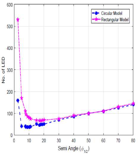
Fig.3. Semi angle vs. No. of LEDs for 'R' = 0
The RMS delay indicates the level of inter-symbol interference (ISI) which largely affects the VLC system’s bandwidth. The mean delay and RMS delay are crucial to determine the data rate of the system. The data rate can easily be depleted by higher interference levels. The increase in RMS delay is the result of multipath propagation. Due to Multipath propagation, the pulse gets spread therefore limiting the system's bandwidth. This necessitates the need to mitigate the effect of multipath that should reduce the RMS delay. So RMS delay has to be minimized as much as possible. In general, the width of the transmitted pulse should be at least ten times as high as the value of RMS delay. This is observed in both the system models that RMS delay increases with increase in LED semi-angle. The narrow semi-angle makes the beam more directional thus such beams can deliver higher data density. However, this can be observed from the respective plot that at extremely lower semi-angles, at optimal value of semi-angle of 15o, the RMS delay of 0.0714 nanoseconds(ns) is achieved whereas, for the circular model, the RMS delay is computed as 0.00694 ns at 10o semi-angle value. This is the optimal scenario where the least number of LEDs not only attains to full mobility but also results in the optimal value of RMS delay. Correspondingly, the maximum RMS delay is obtained as 0.2429 ns and 0.0789 ns respectively for rectangular and circular models. It can also be seen that the RMS value deteriorates as the semiangle is increased which indicates that higher value of semi-angle increases the level of ISI thus increasing the pulse spread. The RMS delay at 80o is observed as 1.65 ns and 1.85 ns respectively for circular and rectangular models which is extremely high as compared to the values obtained at lower semi-angle values. This indicates that higher data rates can be achieved at lower semi-angle values. This can also be observed that RMS delay for the circular structure is marginally lower as compared to the rectangular structure. The maximum and minimum value of RMS delay along with the optimal value of LEDs have been tabulated in table III.
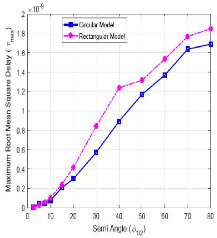
Fig.4. RMS delay (s) vs. LED semi angle for 'R' = 0
-
VI. Conclusion
We have analyzed the LED-based indoor mobile VLC system based on two different structures using HypEA technique. The deployment of LEDs using HypEA for rectangular and circular structures have been investigated extensively. The system mobility parameters especially the average outage area ratio have been discussed with respect to the number of LEDs. The effect of variation of semi-angle on the LED resources has been largely analyzed. Further, the RMS delay parameter has been investigated and its impact on data rate has been studied. A comparison between the two system models has been accomplished accordingly to identify the use of optimal resources for the indoor mobile VLC communication system. Hence, It may be concluded that LED resources can be optimized without degrading the system parameters using HypEA including the computation of the optimal semi-angle value for different structures. In future, the multi-objective problems related to VLC systems could be implemented using HypEA for performance analysis.
APPENDIX - A
Hyper-heuristic Evolutionary Algorithm.
The Hyper-heuristics are defined as heuristics to choose heuristics [35]. It reduces the search effort to find a solution and hence considered as an efficient technique. With the objective of finding optimal solutions, metaheuristic operates directly on the problem search space whereas the hyper-heuristic works on the heuristics search space which contains all the heuristics that is used to solve a given problem. The term hyper-heuristics was coined by Cowling [36]. The hyper-heuristics is able to manage the choice of which lower-level heuristic method is to be applied at any given point of time depending upon the ability of the heuristic in exploring the search space. The basic objective of hyper-heuristics is to evolve more general systems that are able to cater for a wide range of problem domains.
The basic framework of the HypEA is presented in figure 5. There are two phases in which the first phase selects the type of mutation to be adopted. The CR is a random number drawn from the uniform distribution on a unit interval to select an Evolutionary Algorithm (EA) model either with copy or with exchange mutation with equal probability. The values of h b and h e denotes the beginning and ending of the subscripts of low-level hyper-heuristics thus selected. A specific low-level heuristic is selected in the second phase within the
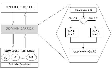
Fig.5. Framework of Hyper-heuristics selected group. The reinforcement learning strategy is used in this phase with adaptive weights using roulettewheel for selecting a specific model of EA. The pseudo code of the HypEA is given in algorithm below.
Algorithm 1 Hyper-heuristic Evolutionary Algorithm (Hy- pEA) ___________________________________________ 1: Initialize parent population
-
2: Evaluate the Illness of parent population
-
3: While (not termination-condition) do
-
4: Select a low-level heuristic based on the selection mechanism
-
5: Apply the selected low-level heuristic on the parent population and obtain offspring population
-
6: Evaluate the offspring population
-
7: Combine parent and offspring populations
-
8: Son the combined population and select the individuals for the next generation
-
9: end while
The general form of the low-level heuristics is depicted as EA/selection/crossover/mutation. Selection pertains to the way in which the parents are selected to generate the offspring. Two types of selection may be used as rand and rand-to-best. In rand mechanism, both the parents are selected randomly from the population, whereas in rand-to-best, one parent is selected randomly from the population and the other parent is elite (the best one). Three types of crossover operators may be used to generate the offspring. The first operator being uniform crossover while the second operator is a hybrid crossover1 (hc1). It is defined by hybridizing the singlepoint crossover with uniform crossover. The third operator is known as hybrid crossover2 (hc2). This is created by the hybridization of two point crossover with uniform crossover. The two types of mutation are referred as - copy and exchange. In the first mutation operator (copy), two genes are selected randomly and the second gene is copied into the first one. In the second mutation operator (exchange), two randomly selected genes exchange their positions[20]. Based on the selection process described above with regards to the crossover and mutation operators, twelve low-level heuristics are designed for the hyper-heuristic. These are expressed in Table IV.
Table 4. Set of Low Level Heuristics Designed for HypEA
|
Group with copy mutation |
Group with exchange mutation |
|
hl: EA/rand/unifornVcopy |
117: BA/rand/unifannfexchange |
|
h2: EA/rand-to-bestfunifornVcopy |
h8 : EA/rand-to-best/unifornV exchange |
|
113: EA/rand/hcl/copy |
h9 : ЕА/rand/hcl/exchange |
|
h4: EA/rind-to-best/hcl/copy |
hlO: EA/rand-to-best/hcl/exchange |
|
h5: EA/rmu№c2/copy |
hl 1 : EA>rand/hc2/ exchange |
|
h6: EA7rand-to-best/hc2/copy |
h 12 : EA/rand-to-best/hc2/ exchange |
The hyper-heuristic selects a promising low-level heuristic at the beginning of every iteration based on the information about the effectiveness of each low-level heuristic accumulated in previous runs. This is implemented through the principle of reinforcement learning [20]. The key idea is to reward improving low- level heuristics during each iteration of the search by increasing its weight and punish poorly performing ones by decreasing its weight.
References Performance Analysis of Rectangular and circular Shape Building Deployment for an Indoor Visible Light Communication System
- A. Kelly, "High-speed GaN micro-LED arrays for data communications," Proceedings of the 14th ICTON Coventry, U.K., pp.1-5, 2012.
- S. Zhang, "1.5 Gbit/s multi-channel visible light communications using CMOS-controlled GaN-based LEDs," Journal of Light wave Technology, vol. 31, no. 8, pp. 1211-1216, 2013.
- Jyoti Madaan, Indu Kashyap, "Vertical Handoff with Predictive Received Signal Strength in Next Generation Wireless Network", International Journal of Computer Network and Information Security(IJCNIS), Vol.8, No.8, pp.27-38, 2016.
- V. Chandrasekhar, J. Andrews, and A. Gatherer, "Femtocell Networks: A Survey," IEEE Communications Magazine, vol. 46, no. 9, pp. 56-67, sep. 2008.
- Y. Tanaka, T. Komine, S. Haruyama, and M. Nakagawa, "Indoor Visible Communication Utilizing Plural White LEDs as Lighting," IEEE International Symposium on Personal, Indoor and Mobile Radio Communications, San Diego, CA, USA, pp. 81-85, vol. 2, Oct.3, 2001.
- G. Auer, "How Much Energy Is Needed to Run a Wireless Network," IEEE Wireless Communications, vol. 18, no. 5, pp. 40-49, Oct. 2011.
- H. Burchardt, N. Serafimovski, D. Tsonev, Stefan Videv and Harald Haas, VLC: Beyond Point-to-Point Communication, IEEE Communications Magazine, pp. 98-105, Jul. 2014.
- Sharma R.K., Kaushal. H., Sharma P.K., "Analysis of indoor FSO link under diffused channel topology," Proceedings of IEEE International Conference on Computing, Communication and Automation (ICCCA), Noida, India, May 2015.
- G. Pang, T. Kwan, C.-H. Chan, and H. Liu, "Led trans light as a communications device", IEEE International Conference on Intelligent Transportation Tokyo, Japan, pp. 788-793, 1999.
- Jupeng Ding, "Evolutionary Algorithm Based Power Coverage Optimization for Visible Light Communications", IEEE Communications Letters, vol. 16, no. 4, pp. 439-441, Apr. 2012.
- J. P. Ding and Y. F. Ji, "Evolutionary algorithm-based optimization of the signal to noise ratio for indoor visible-light communication utilizing white light-emitting diode,'' IET Optoelectronics, vol. 6, no. 6, pp. 307-317, Sep. 2012.
- Rui Guan, Jin Yuan-Wang, Yun Peng-Wen, Jun Bo-Wang, "PSO-based LED deployment optimization for visible light communications", IEEE International Conference on Wireless Communications and Signal Processing (WCSP), China, pp. 24-26 Oct. 2013.
- C. Chow, C. Yeh, Y. Liu, P. Huang, and Y. Liu, "Adaptive scheme for maintaining the performance of the in-home white-led visible light wireless communications using OFDM, " Optics Communications, vol. 292, no. 1, pp. 49- 52, 2013.
- Y. Wang, N. Chi, J. Yu, and H. Shang, "Demonstration of 575-mb/s downlink and 225-mb/s uplink bi-directional scm-WDM visible light communication using RGB led and phosphor-based led'' Optics Express, vol. 21, no. 1, pp. 1203-1208, 2013.
- M. Biagi, T. Borogovac, and T. Little, "Adaptive receiver for indoor visible light communications, " Journal of Lightwave Technology, vol. 31, no. 23, pp. 3676-3686, 2013.
- A. Nabih, Z. Rashed, "Optimization Design Parameters of Electro-optic Modulators for Low Loss Wide Bandwidth Capability of Optical Communication Systems," International Journal of Computer Network and Information Security(IJCNIS), Vol. 4, No. 5, June 2012.
- R. Sharma, M. Aggarwal, S. Ahuja, "Performance Analysis of Indoor FSO Communication Systems Under Receiver Mobility," IEEE International Conference on Micro-Electronics and Telecommunication Engineering (ICMETE)} Ghaziabad, India, 2016.
- R. Sharma, M. Aggarwal, S. Ahuja, "Channel Capacity and BER Estimation of Indoor Optical Wireless Communication System Under receiver mobility, "Journal of Optical Communication," De Gruyter, 2017.
- G.Kendall and M.Mohamad, "Channel assignment optimization using a hyper-heuristic," Proceedings of IEEE Conference on Cybernetics and Intelligent Systems, pp.791-796, 2004.
- A. Charan Kumari and K.Srinivas, "Hyper-heuristic approach for multi-objective software module clustering", Journal of Systems and Software, Volume 117, Pages 384-401, July 2016.
- D. Bykhovsky and S. Arnon, "Multiple access resource allocation in visible light communication systems," Journal of Lightwave Technology, vol. 32, no. 8, pp. 1594-1600, 2014.
- S. Arnon, "Visible Light Communication," Cambridge University Press, Feb. 2015.
- R. F. Karlicek, "Smart lighting-Beyond simple illumination," in Photonics Society Summer Topical Meeting Series, IEEE, pp. 147-148, 2012.
- W. W. R. Forum, Available: http://www.wwrf.ch/, 2014
- O. H. G. Access. Available: http://www.ict-omega.eu/
- IEEE 802.15 WPAN™ Task Group 7 (TG7), Visible Light Communication, Available: http://www.ieee802.org/15/ pub/TG7.html, 3 March 2015.
- T. Kishi, H. Tanaka, Y. Umeda, and O. Takyu, "A High-speed LED driver that sweeps out the remaining carriers for visible light communications," Journal of Lightwave Technology, vol. 32, pp. 239-249, 2014.
- G. M. Lazzerini, F. Di Stasio, C. Flechon, D. J. Caruana, and F. Cacialli, "Low-temperature treatment of semiconducting interlayers for high-efficiency light emitting diodes based on a green-emitting polyfluorene derivative," Applied Physics Letters, vol. 99, no. 24, 2011.
- Z. Ghassemlooy, W. Popoola, and S. Rajbhandari, Optical Wireless Communications: System and Channel Modeling with MATLAB. Boca Raton, FL: Taylor & Francis Group, 2012.
- G. Cossu, A. M. Khalid, P. Choudhury, R. Corsini, and E. Ciaramella, "3.4 Gbit/s visible optical wireless transmission based on RGB LED," Opt. Exp., vol. 20, pp. B501–B506, 10 Dec. 2012.
- J. Vucic, C. Kottke, S. Nerreter, K. Habel, A. Buttner, K. D. Langer, and J. W. Walewski, "230 Mbit/s via a wireless visible-light link based on OOK modulation of phosphorescent white LEDs," in Proc. Opt. Fiber Communication./Nat. Fiber Opt. Eng. Conf., pp. 1–3, 2010.
- Mehdi Rouissat, A. Riad Borsai, M. Chikh-Bled, "Isochronous and Anisochronous Modulation Schemes in Wireless Optical Communication Systems ", IJIEEB, vol.4, no.3, pp.19-25, 2012.
- J. M. Kahn and J. R. Barry, "Wireless infrared communications," IEEE Proceedings, vol. 85, no. 2, pp. 265-298, Feb. 1997.
- T. Komine and M. Nakagawa, "Fundamental Analysis for Visible Light Communication System using LED Lights, " IEEE Transactions on Consumer Electronics, Vol. 50, No. 1, 2004
- E. Burke, G. Kendall, J. Newall, E. Hart, P. Ross and S. Schulenburg, "Hyper-heuristics: an emerging direction in modern search technology," in Handbook of meta-heuristics. F. Glover and G.A. Kochenberger, Ed. Kluwer Academic Publishers, pp. 457-474, 2003.
- P. Cowling, G. Kendall and E. Soubeiga, "Hyper-heuristic Approach to Scheduling a Sales Summit," in Proceedings of the Third International Conference of Practice And Theory of Automated Timetabling, pp. 176-190, 2001.
