Performance comparison of steganography techniques

Author: Rinku Sharma, Reema Ganotra, Sangeeta Dhall, Shailender Gupta
Journal: International Journal of Computer Network and Information Security @ijcnis
Article in issue: 9 vol.10, 2018.
Free access
Confidentiality calls for substantial research and development in network security and data communication. Several techniques have been proposed for the past decades to ensure secure and confidential transmission of data. Steganography is a significant method of hiding data in another media, such that it is physically and virtually invisible. It is used primarily to ensure secure communication in an indiscernible fashion so that the hidden information is not discovered at any stage. The goal is to hide the presence of secret information rather than the contents of information to avoid breaching of data confidentiality. This paper is an effort to bring about a comparison of some of the recent techniques used for steganography on the basis of embedding capacity and Peak signal to noise ratio (PSNR), Universal image quality index (UIQI), Number of pixel change rate (NPCR) and correlation. The performance metrics undertaken are robustness, security analysis and perceptual quality. The techniques were implemented in MATLAB 2013a v 8.1.0.604.
Steganography, BPCS, PSNR, Entropy
Short address: https://sciup.org/15015632
IDR: 15015632 | DOI: 10.5815/ijcnis.2018.09.04
Text of the scientific article Performance comparison of steganography techniques
Published Online September 2018 in MECS DOI: 10.5815/ijcnis.2018.09.04
Good quality network security is an integral part of data communication infrastructure. With the growth in intelligent transmission and communication networks, a breech in security is a matter of concern [1, 2, 3]. The ITRC report gives the number of data breaches which demonstrates that the numbers have taken a great hike over the years. This is shown as in the figure 1:
One primary clause that ensures secure data communication is data confidentially. Steganography produces an efficient mechanism for secure transmission of sensitive data [3, 4, 5]. The data is embedded in a cover media in a fashion such that its existence is not detected by an intruder. The most basic steganography technique uses an image to hide the secretive information .This is demonstrated as in figure 2.
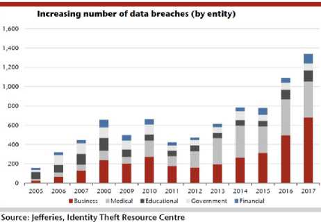
Fig.1. ITRC Report for Number of Data Breaches in years 2005-2017
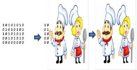
Fig.2. The Basic Scheme of Steganography
This paper compares most of the popular steganography techniques which have good embedding capacity and robustness. The rest of the paper is organized as follows: Section II explains the techniques implemented. Section III gives simulation set-up parameters. Section IV gives the snapshots. Section V provides the performance metrics on the basis of which results and conclusion are formulated in section VI and VII respectively.
-
II. Technniques Implemented
The implemented steganography techniques are described in this section.
-
A. Implementation using BPCS
BPCS stands for Bit Plane Complexity segmentation [14]. The last plane of the cover image is a complex noisy plane which is used for embedding. The First step in BPCS is to segment the cover image into 8 planes. Blocks of 8x8 are formulated of each plane. After block segmentation, canonical gray code conversion is applied on pure binary codes present in each block.
The next step is to divide the data into 8x8 blocks. Complexity is calculated for each data that is to be embedded. The complexity ( α ) is given by
к
м
Where, α should be lie from 0 to 1.
M is the total number of blocks and k is total no. transition changing from white to black or vice versa.
Threshold value is computed by:
th =«* Стах (2)
Where, Cmax is maximum complexity of Block. This threshold value acts as cut-off for block selection i.e. the blocks having complexity value greater than the threshold value are opted for embedding. Also complexity for data blocks is calculated to check whether it should be embedded without modifications or some needs to be done. If the complexity of the data block is greater than the threshold it is embedded into the image blocks directly. Otherwise, the conjugate of the block is taken to be embedded into the image block as shown in figure 3.
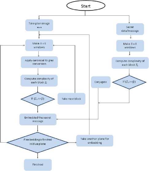
Fig.3. BPCS Steganography
Algorithm: Embedding Block
Input: secret message
Output: Embedding block
Step 1: Take secret message.
Step 2: Make 8x8 window of secret message.
Step 4: Calculate complexity of each Block.
Step 5: Select threshold values on the Base of complexity value
Step 6: Take direct data for embedding whose complexity value greater then to threshold value else take conjugate.
Algorithm: Stego Image
Input: Plain image Im MXN where M, N are height and width of the image, secret message (embedding block).
Output: Stego Image
Step 1: Take plain image (m x n) where M, N are the height and width.
Step 2: Make 8x8 window of entire image.
Step 3: Apply canonical to gray conversion of all windows.
Step 4: Calculate complexity of each Block.
Step 5: Select threshold values on the Base of complexity value
Step 6: Select that block whose complexity value is grater then threshold value.
Step 7: Embed the secret message into blue plane.
Step 8: Take another plane if embedding in blue plain is finished.
-
B. Implementation using Status Bit
The first step in Status bit Steganography involves the extraction of the R, G and B planes from the cover media. The most significant bits of each plane are taken and their decimal equivalent is computed [10, 11, 12,13, 14, 15] then, the binary values of the pixels in the blue plane are computed. Embedding Decision would be taken on the basis of darker and lighter pixels.
If the MSB bits contains at least two “1” bits, then the pixel is called as lighter pixel. If the MSB bits contains at least two “0” bits, then the pixel is called as lighter pixel . The decimal equivalent (Zn) of the three MSB bits of each RGB pixels is used to decide the position of embedding in blue plane.
Embedding in lighter pixels : - If the bit position ‘Zn’ and message bit is same, then change the LSB bit of the pixels of blue plane into 1 otherwise make it 0.
Embedding in darker pixels: - If the bit position ‘Zn’ and message bit is same, then change the LSB bit of the pixels of blue plane into 1, otherwise make it 0. Here, there is one more condition that if all the MSB bits of pixels are 0, then directly inserts the message in blue plane
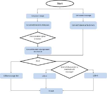
Fig.4. LSB Status Steganography
Algorithm: compute the lighter and darker pixels
Input: Plain image Im MXN where M, N are height and width of the image, data.
Output: Stego image
Step 1: Take plain image
Step 2: Make 3x3 windows of plain image.
Step 3: Collect the MSB bits from a pixel {R, G, B} color space.
Step 4 : For darker pixels- if the MSB bits contain at least two bit 1, then the pixels is used for data hiding.
Step 5: For lighter pixels- if the MSB bits contain at least two bit 0, then the pixels is used for data hiding.
Algorithm: Embedding data in darker pixels
Input : Darker pixels of Blue planes
Output : Stego image
Step1 : The decimal representation Z n of three MSB bits of RGB pixels are used for determining the position in blue plane. Now if bit position Zn and message bit is same then change the LSB bits of the pixels of blue plane into1 otherwise 0.
Algorithm: Embedding data in lighter pixels
Input : lighter pixels of Blue planes
Output : stego image
Step 1: The decimal representation Zn of three MSB bits of RGB pixels is used for determining the position in blue planes. If the bit position Zn and message bit is same then change the LSB bits of the pixels of blue plane into 1 otherwise 0.
Step 2 : If all three MSB bits of pixels are 0 then in this situation directly insert the message bit in blue plain.
-
C. Implementation using LSB Steganography
In the first step of this technique, the binary value of the pixels in the image and that of the message is computed. The LSB of pixel is then compared with the corresponding bit of the message [4, 5, 6, 7, 8, 9]. If the message bit and LSB of pixel are found to be same, no change in the pixels ensues. If they are found to be different, an increment or a decrement in the LSB of corresponding pixel is undertaken for embedding the data.
The whole message length is traversed for comparison with corresponding pixels’ LSB till the end of the message is reached. The rest of the pixels in the image are unchanged. The process is shown in figure 5.
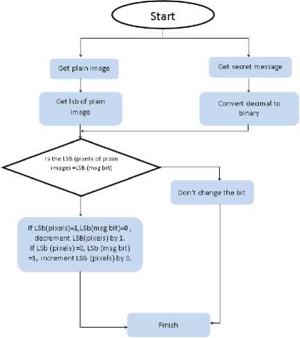
Fig.5. LSB using Steganography
Algorithm: Stego Image
Input: Plain image ImMXN where M, N are height and width of the image, data.
Output : Stego image
Step 1: Take plain image
Step 2: Take the LSBs of all pixels of Plain Image
Step 3: Convert the data, decimal to binary
Step 4: If the LSB of image pixels not equal to msg bit then don’t change the LSB of image pixels.
Step 5: a) If LSB(pixels of plain image)=1,LSB(msg bit)=0 , then decrement LSB(pixels) by 1.
-
b) If LSB (pixels of plain image) =0, LSB (msg bit) =1, then increment LSB (pixels) by 0.
S tep 6: Transmit the stego Image.
-
D. Implementation using LSB based Image Steganography using Secret Key
To hide the secret information, the cover image is divided into three planes (Red, Green and Blue). After dividing each plane, the secret key is chosen on the basis of user. The secret key is converted into one-dimension array of bit stream [16, 17,18, 19, 20].
Secret key and red plane are used only for decision making to hide the information into either Green plane or Blue plane. Each bit of secret key is ex-ored with the LSB of red plane. The obtained ex-or results decide that the information will be embedded in either Green plane or Blue plane.
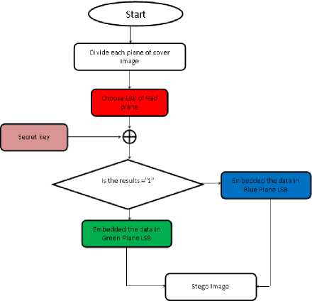
Fig.6. LSB based Image Steganography using Secret Key
Table 1. Simulation Setup Parameters
|
Parameter |
Values |
|
Data size |
16X16 (color image) |
|
Image size |
256 x 256 512 x 512 1024 x 1024 |
|
Image category |
Color image (.bmp format) |
|
Programing language tool |
MATLB 2013a v 8.1.064 |
|
Simulation implemented |
64 bit MATLAB |
|
Processor |
1.4 Ghz dual core Intel i5 |
|
Memory size |
4 GB/1TB of1600 Mhz LPDDR3 |
-
IV. Snapshots
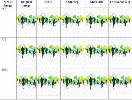
Relationship of original image and stego image obtained by implementation of steganography techniques is described in table 2.
Algorithm: Stego Image
Input: Plain image Im MXN where M, N are height and width of the image, secret key data.
Output : Stego image
Step 1: Take plain image
Step 2 : Divide image into three planes (R, G, and B).
Step 3: Convert the secret key into binary, if it is then keep it as such.
Step 4: Convert the secret key into one dimension array.
Step 5: Ex-or each bit of secret key with LSB of Red plane.
Step 6: Change the LSB of Green plane pixel if Ex-or result is 1 else, embed the data in LSB of Blue plane pixel. Step.7: Transmit the stego image.
NOTE: Decryption process of each technique is just reverse as like encryption.
III. Simulation Setup Parameters
Hardware and software requirement for simulation and implementation of intended steganography techniques are given in table 1.
Table 3. Comparison of Histogram for 256 x 256 Images
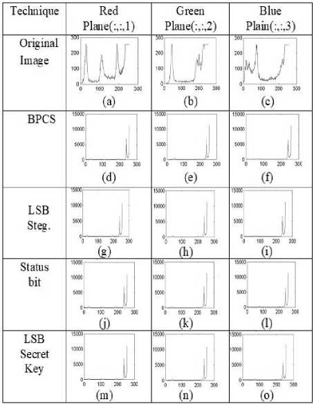
Table 2. Comparison of stego Image
-
A. Histogram Analysis for 256 x 256 Image
Relationship of original image and stego image histogram analysis found by implementation of steganography techniques is described in table 3.
-
B. Histogram Analysis for 512 x 512 Image
Table 4. Comparison of Histogram for 512 x 512 Images
|
Techniq ue |
Red Plane(:,:,1) |
Green Plane(:,:,2) |
Blue Plain(:,:,3) |
|
Original Image |
0------------------ 0 100 200 300 (a) |
p % 100 200 300 (b) |
™Пi J 100 % 100 200 300 (C) |
|
BPCS |
% 100 200 300 (d) |
% 100 200 300 (e) |
% 100 200 300 (f) |
|
LSB Steg. |
0 100 200 300 (g) |
___и 0 100 200 300 (h) |
% 100 МО ж (i) |
|
Status bit |
3 2 % 100 200 300 (j) |
% 100 200 300 (k) |
% 100 MO 300 (l) |
C. Histogram Analysis for 1024 x 1024 Image
Table 5. Comparison of Histogram for 1024 x 1024 Images
|
Technique |
Red Plane(:,:,1) |
Green Plane(:,:,2) |
Blue Plain(:,:,3) |
|
Original Image |
% 100 2 00 300 (a) |
200 o'---- 0 100 200 300 (b)` |
100 200 300 (c) |
|
BPCS |
0 100 200 300 (d) |
' ll % 100 200 300 (e) |
100 200 300 (f) |
|
LSB Steg. |
% 100 200 SOO (g) |
% 200 300 (h) |
21-------------------------- 1.5 0 100 200 300 (i) |
|
Status bit |
°C 100 200 300 (j) |
% 100 200 Ж (k) |
% 100 200 Ж (l) |
|
LSB Secret Key |
1.5 ■ 0 100 200 300 (m) |
100 200 300 (n) |
% 100 200 MO (o) |
(a) Shows the histograms of Red plane of original image (b) Shows the histograms of Green plane of original image (c) Shows the histograms of Blue plane of original image (d) Shows the histograms of Red plane using BPCS Technique (e) Shows the histograms of Green plane using BPCS Technique (f) Shows the histograms of Blue plane using BPCS Technique (g) Shows the histograms of Red plane using LSB Steganography Technique (h) Shows the histograms of Green plane using LSB Steganography Technique (i) Shows the histograms of Blue plane using LSB Steganography Technique (j) Shows the histograms of Red plane using status bit Steganography Technique (k) Shows the histograms of Green plane using status bit Steganography Technique (l)Shows the histograms of Blue plane using status bit Steganography Technique (m) Shows the histograms of Red plane using LSB Secret key Steganography Technique (n) Shows the histograms of Green plane using LSB Secret key Steganography Technique (o) Shows the histograms of Blue plane using LSB Secret key Steganography Technique.
-
V. Performance Metrics
For thorough exploration of the techniques, three analyses were performed that are explained in the subsequent section.
-
A. Security Analysis
For security analysis, histograms of original image and encrypted-image are matched. A technique is said to be secure when the difference in the histograms is negligible which means the parameter values lie close to its ideal values. The parameters which are used for security analysis are listed below:
-
• Jaccard Index:
The Jaccard index, also known as the Jaccard similarity coefficient is used for comparing similarity between the original image and the encrypted-image. The jaccard index is mathematically given by the formula
J(x,Y) =
X П Y
XUY
Where, X is the original image and Y is the encrypted-image
J (X, Y) is the jaccard index between image matrices X and Y
X П Y is the intersection of matrices X and Y
X U Y is the union of matrices X and Y
The value of Jaccard index lies between 0 and 1. 1 signifies perfect matching and 0 signifies total mismatch.
-
• Correlation Coefficient:
The correlation coefficient is a measure of the linear correlation (dependence) between two images X and Y , giving a value between +1 and -1 inclusive, where 1 signifies perfect match and -1 signifies total mismatch. The correlation coefficient is given by the formula
° X ° Y
Where, X is the original image and Y is the stego-image
p(X,Y") is the correlation coefficient between image matrices X and Y cov (X , Y) is the covariance between matrices X and Y ox is the standard deviation of X oY is the standard deviation of Y
-
• Intersection Coefficient:
Intersection coefficient of histograms counts the common number of pixels of same value between two histograms (histograms of cover image and stego-image). The intersection coefficient is given by the formula:
N
I(X,Y)=^
1=1
min(X(i), Y(i))
Where, X is the original image and Y is the stego-image
I(X,Y) is the intersection coefficient between image matrices X and Y
X and Y are the probability distributions of images A and B respectively
If value of intersection coefficient is 1 it signifies perfect match and if the value is 0 it signifies total mismatch.
-
• Bhattacharyya Coefficient:
The Bhattacharyya coefficient measures the similarity between two images by using their probability distributions. The formula for Bhattacharyya coefficient is given by:
N
1=1
Where, A is the original image and B is the stego-
C(X,Y) =
2^ x ^ y
Ox2 + Oy2
S(X,Y) -
2oxy
Ox + O y
Where, X is the original image and Y is the stego-image
Bx is the mean of matrixX
By is the mean of matrix Y ox is the standard deviation of matrixX oy is the standard deviation of matrix Y oxy is the covariance between matricesX and Y
-
B. Robustness Analysis
Robustness analysis is performed to measure the quality of image after implementation of particular technique. The parameters used for analysis of robustness are given below:
-
• Mean Square Error (MSE):
This parameter is a quantitative representation of the error that occurs in the final stego-image with respect to the original image. For a colour image MSE is given by:
"«-T^kiZcfZr^Z.Ull'-'X-Y)-FC~(X, Y)]л2
Where, M x N is the size of image (height and width respectively)
C=1 to 3 denotes the Red, Green and Blue colour plane respectively
Fc (X, Y)=value of pixel at position (X, Y) in c colour plane of cover image
Fc~(X, Y)=value of pixel at position (X, Y) in c colour plane of stego-image image
BC (A, B) is the Bhattacharyya coefficient between image matrices A and B
X and Y are the probability distributions of images A and B respectively
If value of Bhattacharyya coefficient is 1 it signifies perfect match and if the value is 0 it signifies total mismatch.
-
• Universal Image Quality Index(UIQI):
UIQI is used to measure the changes in stego-image with respect to the cover-image. In this measure the comparison of the images is broken down into three comparisons: luminance (L), contrast (C) and structural comparison (S).
L(X,Y) =
2 B x B y
Bx2 + By2
-
• Mean Absolute Error (MAE):
MAE is the average of absolute errors between the cover image and the stego-image. For a colour image the formula for MSE is given by:
MAE = ^^ 3 У N У M /6s [ fc ( x,y ) -
Mx«x3 c = 1 У - 1 X = 1 fc~(x,y)]2
Where, M x N is the size of image (height and width respectively)
C=1 to 3 denotes the Red, Green and Blue colour plane respectively
Fc (X, Y)=value of pixel at position (X, Y) in c colour plane of cover image
Fc ~ (X, Y)=value of pixel at position (X, Y) in c colour plane of stego-image
-
• Peak Signal to Noise Ratio (PSNR):
PSNR is the most commonly used parameter to measure the quality of image after embedding. Higher the PSNR value, higher the robustness of the stego-image. PSNR value is most commonly defined in terms of MSE. The formula for PSNR is given as:
PSNR = lOlog io (^L)
Where MAX is the maximum value of a pixel in the image. It is 255 for colour image of 8 bits.
-
VI. Results
-
A. Robustness
Robustness of a steganography technique can be measured by calculating the PSNR, MSE and entropy of stego image with respect to original image.
-
• PSNR
Peak signal to noise ratio shows the changes of original message with respect to the stego Image. As per result observation the best results shows by LSB and LSB Secret Key Steganography Techniques. This is shown in figure 7.
PSNR
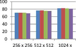
Image Size
key based encryption stegaonography lsb based stegaonography
status bit stegaonography
BPCS steganography
Fig.7. Comparison of PSNR
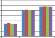
MSE
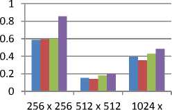
Image Size
key based encryption stegaonography lsb based stegaonography
status bit stegaonography
BPCS steganography
-
• MSE
MSE shows the quantitative representation of the error that occurs in the final stego-image with respect to the original image. This is shown in figure 8.
-
• Entropy
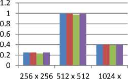
Entropy is important factor in terms of robustness. It shows that the probability of occurrence of pixels in encrypted image should be equal to the original plain image. So the maximum value of entropy is provided by the Status bit. This is shown in figure 9.
ENTROPY
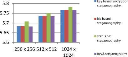
Image Size
Fig.9. Comparison of Entropy
-
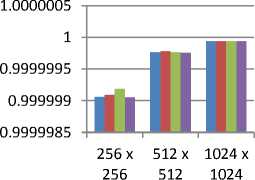
• Correlation Coefficient
0.9999995
0.999999
0.9999985
0.999998
0.9999975
0.999997
This parameter is used to find the linear correlation between two images. Its value must lie between (-1, 1). In this scheme the best results are shown by the LSB and Status bit Steganography technique. This is shown in figure 10.
Correlation
1.0000005
256 x 512 x 1024 x
256 512 1024
key based encryption stegaonography lsb based stegaonography status bit stegaonography
BPCS steganography
Image Size
Fig.10. Comparison of Correlation Coefficient
-
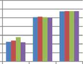
• Intersection Coefficient
Intersection coefficient of histogram of original and stego image is used to calculate the common number of pixels of same value between two images. The best results are shown by the BPCS and Status bit Steganography techniques. This is shown in figure 11.
Fig.8. Comparison of MSE
Intersection Coefficient
Imaze Size
key based encryption stegaonography lsb based stegaonography
status bit stegaonography
BPCS steganography
Fig.11. Comparison of Intersection Coefficient
-
• Jaccard Index
This factor is used to find the similarity between cover image and Stego Image. Its value also must lie in between (-1, 1). So the best results are provided by the LSB and BPCS Steganography techniques. This is shown in figure 12.
-
VII. Overall Comparison
-
A. PSNR:-
- Table 6 shows the comparison of PSNR values of all techniques.
Table 6. Comparison of PSNR
|
Image size |
BPCS Steganogra phy |
Status bit Steganogra phy |
LSB Steganogra phy |
LSB Secret Key Steganogra phy |
|
256 X 256 |
68.8033945 |
70.3607312 |
70.4184932 |
70.4297298 |
|
90476415 |
22298767 |
64726976 |
68198535 |
|
|
512 X 512 |
75.1284188 |
75.5753674 |
76.5797522 |
76.2956029 |
|
51299998 |
94174571 |
6306192 |
14916088 |
|
|
1024 X 1024 |
81.2582633 |
81.8087767 |
82.6508746 |
82.1633040 |
|
8168936 |
27900437 |
99263284 |
02255515 |
-
B. MSE:-
- Table 7 shows the comparison of MSE values of all techniques. 0.99998 0.99996 0.99994 0.99992 0.9999 0.99988
Jaccard Index
1.00002
256 x 512 x 1024 x
256 512 1024
-
■ key based encryption stegaonography
-
■ lsb based stegaonography
status bit stegaonography
-
■ BPCS steganography
Image Size
Fig.12. Comparison of Jaccard Index
Table 7. Comparison of MSE
|
Imag e size |
BPCS Steganograp hy |
Status bit Steganograp hy |
LSB Steganograp hy |
LSB Secret Key Steganogra phy |
|
256 X 256 |
0.85652669 |
0.59842156 |
0.59051513 |
0.58898925 |
|
270833337 |
921659362 |
671875 |
78125 |
|
|
512 X 512 |
0.19963582 |
0.18011239 |
0.14292399 |
0.15258789 |
|
356770834 |
925675135 |
088541669 |
0625 |
|
|
1024 X 1024 |
0.48669179 |
0.42874857 |
0.35317738 |
0.39513905 |
|
280598956 |
347686596 |
850911456 |
843098956 |
-
• UIQI
This parameter is used to measure the modifications in stego image with respect to the cover image. The best results shown by the Bpcs steganography and status bit steganography as shown in below.
-
C. Entropy:-
- Table 8 shows the comparison of Entropy values of all techniques
UIQI
-
■ key based encryption stegaonography
-
■ lsb based stegaonography
status bit stegaonography
-
■ BPCS steganography
Image Size
Fig.13. Comparison of UIQI
Table 8. Comparison of Entropy
|
Image size |
BPCS Steganogra phy |
Status bit Steganograp hy |
LSB Steganograp hy |
LSB Secret Key Steganogra phy |
|
256 X 256 |
5.6819561 |
5.70831778 |
5.684018599 |
5.6837178 |
|
067912518 |
47660442 |
9671187 |
965130013 |
|
|
512 X 512 |
5.7351863 |
5.74952317 |
5.736882404 |
5.7372235 |
|
467407274 |
40143229 |
4255113 |
001117264 |
|
|
1024 X 1024 |
5.7665946 |
5.78113672 |
5.767116194 |
5.7672020 |
|
878979781 |
38206337 |
0310984 |
404465014 |
-
D. Correlation Coefficient:-
- Table 9 shows the comparison of Correlation Coefficient values of all techniques.
Table 9. Comparison of Correlation
|
Image size |
BPCS Steganogra phy |
Status bit Steganograp hy |
LSB Steganogra phy |
LSB Secret Key Steganogra phy |
|
256 X 256 |
0.99999810 |
0.999998381 |
0.99999819 |
0.99999813 |
|
116155885 |
85416845 |
285453684 |
045791908 |
|
|
512 X 512 |
0.99999951 |
0.999999532 |
0.99999955 |
0.99999953 |
|
298750989 |
35229688 |
973976529 |
53833081 |
|
|
1024 X 1024 |
0.99999987 |
0.999999884 |
0.99999988 |
0.99999987 |
|
80502577 |
73720525 |
509118853 |
16463776 |
-
E. Intersection Coefficient:-
- Table 10 shows the comparison of Intersection Coefficient values of all techniques.
Table 10. Comparison of Intersection Coefficient
|
Image size |
BPCS Steganogra phy |
Status bit Steganograp hy |
LSB Steganogra phy |
LSB Secret Key Steganogra phy |
|
256 X 256 |
0.24835840 |
0.23154428 |
0.24835603 |
0.24835348 |
|
680893925 |
191046689 |
495373784 |
610465022 |
|
|
512 X 512 |
0.99388411 |
0.97536470 |
0.99388273 |
0.99388165 |
|
257678544 |
775934314 |
850978004 |
801008865 |
|
|
1024 X 1024 |
0.39675645 |
0.38939569 |
0.39675627 |
0.39675606 |
|
302009649 |
632666965 |
452248408 |
75920393 |
-
F. Jaccard Index
Table 11 shows the comparison of Jaccard Index values of all techniques.
Table 11. Comparison of Jaccard Index
|
Imag e size |
BPCS Steganogra phy |
Status bit Steganograp hy |
LSB Steganogra phy |
LSB Secret Key Steganogra phy |
|
256 X 256 |
0.99992834 |
0.999927879 |
0.99993178 |
0.99992940 |
|
898345062 |
38723726 |
394441506 |
831655186 |
|
|
512 X 512 |
0.99998164 |
0.999981582 |
0.99998340 |
0.99998248 |
|
163912162 |
79648375 |
156047349 |
335717332 |
|
|
1024 X 1024 |
0.99999537 |
0.999995438 |
0.99999564 |
0.99999513 |
|
926377824 |
16509651 |
578961153 |
630288095 |
-
G. UIQI
Table 12 shows the comparison of UIQI values of all techniques.
Table 12. Comparison of UIQI
|
Imag e size |
BPCS Steganogra phy |
Status bit Steganograp hy |
LSB Steganogra phy |
LSB Secret Key Steganogra phy |
|
256 X 256 |
0.99992834 |
0.999927879 |
0.99993178 |
0.99992940 |
|
898345062 |
38723726 |
394441506 |
831655186 |
|
|
512 X 512 |
0.99998164 |
0.999981582 |
0.99998340 |
0.99998248 |
|
163912162 |
79648375 |
156047349 |
335717332 |
|
|
1024 X 1024 |
0.99999537 |
0.999995438 |
0.99999564 |
0.99999513 |
|
926377824 |
16509651 |
578961153 |
630288095 |
-
VIII. Conclusions
In this paper various steganography techniques has been implemented for confidentiality and security purpose. The human perceptibility of blue plane is known to be very low as compared to any other plane. So, the data hidden in blue plane is considered to be much secure. Therefore, in BPCS technique all the data was embedded in complex noisy blue plane. The embedding capacity of BPCS techniques and LSB techniques is high. On comparison, it is found that the LSB steganography and LSB using secret key perform the best on the basis of PSNR. According to entropy and correlation point of view, the best results are shown by the status bit and BPCS steganography techniques.
References Performance comparison of steganography techniques
- Piyush Marwah (2010) Visual Cryptography Steganography in images. In processing of second International conference on Computing, Communication and networking Technologies, pp. 1-6.
- Gokul M, Umeshbabu R, Vasudevan SK (2012) Hybrid Steganography using Visual cryptography and LSB encryption method. Int J computes Appl 59 5-8.
- S.M. Masud Karim, Rahman MS (2011) A new approach for LSB based Image steganography using secret key. In proceedings of 14th international conference on computer and information Technology, pp. 286-291.
- Shailender Gupta, Ankur Goyal, Bharat Bhushan (2012) Information hiding using least significant steganography and cryptography. In I.J. Modern Education and Computer Science 6: 27-34.
- Chaudhary D, Gupta S, Kumari M (2016) A novel hybrid security mechanism for data communication networks. International Journal of information privacy, Security and integrity 2(3):2166-231.
- Ritesh B, Shailender Sharma G (2016) An innovative image encryption scheme based on chaotic map and vigenere scheme. Multimedia Tools and Application 1-34. doi:10.1007/s11042-016-3926-9.
- Chaudhary D, Gupta S, Sweety Deswal (2015) origin of Hybrid security mechanism and ways of improvement. In international journal of Big Data security Intelligence doi:10.21742/ijbdsi.2015.2.2.01 pp. 1-22.
- Nivedhita R. and meyyappan T. (2012) Image security using Steganography and Cryptography Techniques. In international journal of Engineering trends and Technology, Vol. 3, pp.366-371.
- Mohammad A, Yahya A (2010) public- Key steganography based on matching method. Eur j Sci Res 40(2):223-231.
- Ramakrishna Mathe, Atukuri V, and Devireddy SK, (2012) securing Information Cryptography and steganography. In International Journal of Computer Science and Information Technologies, Vol.3, pp 4251-4255.
- Islam MR, Siddiqa A, Uddin MP(2014) An efficient filtering based approach improving LSB image Steganography using status bit along with AES cryptography. In proceedings of 3rd International Conference on informatics, Electronics and vision, pp 1-6.
- Shingote Parshuram N, Syed A (2014) Advanced security using Cryptography and LSB matching Steganography. International journal of comp. and Elec. Research 3(2):52-55.
- S. Gupta, A Goyal, B Bhushan (2012) Information hiding using least significant bit steganography and Cryptography. In I.j. Modern Education and comp. Science 6:27-34.
- Tayal N., Bansal R., Dhal S., Gupta S (2016) A novel hybrid security mechanisms for data Communication networks. Doi: 10.1007/s11042-016-4111-x.
- Singh, A., Malik (2013) securing data by using cryptography with steganography. In international journal of advanced research in comp. science and software Eng. pp. 404-409, ISSN: 2277-128X.
- Nivedhitha R, DT Meyyappan, Phil M (2012) Image security using steganography and cryptographic techniques. In international journal of engineering trends and technology, vol. 3, pp. 366-371.
- Shamir A (1979) How to share a secret comm. ACM 22(11): 612-613.
- V. Padmavathi, B.V. Vardhan, A. V. N Krishna (2016) Quantum Cryptography and Quantum Key Distribution Protocols: A Survey. 2016 IEEE 6th international conference on Advanced Computing DOI:10.1109/IACC.2016.109.
- Ahmed A. Abd EI-Latif, Li Li, Ning wang, Qi Han, Xiamu Niu (2012) A new approach to chaotic image encryption based on Quantum Chaotic System, exploiting Color spaces. Doi: 10.1016/j.sigpro.2013.03.031.
- Alvarez G., S. Li, (2006) some basic cryptography requirement for chaos-based cryptosystem, international journal of bifurcation and chaos 16.2129-2151.
