Performance Evaluation of Super Resolution Image Reconstruction using IWT and BPT with Different Colour Transforms

Author: P.Ashok Babu, K.V.S.V.R.Prasad
Journal: International Journal of Image, Graphics and Signal Processing(IJIGSP) @ijigsp
Article in issue: 11 vol.6, 2014.
Free access
Super resolution (SR) images play an important role in Image processing applications. Spatial resolution is the key parameter in many applications of image processing. Super resolution images can be used to improve the spatial resolution. In this paper a new SR image reconstruction algorithm is proposed using Integer wavelet transform (IWT) and Binary plane technique (BPT). The proposed method is analyzed in different color space transforms such as CIELAB, YCbCr and RGB. In this paper we compared PSNR, ISNR, Blocking effect and Homogeneity with different colour images in RGB, YCbCr and CIELAB domains. Qualitative analysis shows that the proposed method in CIELAB color space transforms has better performance.
Super Resolution, Bi Cubic Interpolation, YCbCr, CIELAB, IWT, and BPT
Short address: https://sciup.org/15013450
IDR: 15013450
Text of the scientific article Performance Evaluation of Super Resolution Image Reconstruction using IWT and BPT with Different Colour Transforms
Published Online October 2014 in MECS
Image Super-Resolution (SR) is a technique which aims at the estimation of a High-Resolution (HR) image from one or several Low-Resolution (LR) images that promises to overcome some of the inherent resolution limitations of low-cost imaging sensors ( e.g. , cell phone cameras or surveillance cameras), and allows better utilization of the growing capability of HR displays ( e.g. , HD LCDs).The problem of SR image reconstruction is first discussed by T. S. Huang and R. Y. Tsai [1]. Conventional super-resolution approaches normally require multiple LR inputs of the same scene with subpixel motions. Thus the SR method cast as an inverse problem of recovering the original HR image by fusing the LR inputs, based on reasonable assumptions or prior knowledge about the observation model.
Ideally, the low resolution images would differ only in small sub-pixel translations. In practice, the transformations can be more substantial that involves rotations or more complex geometric distortions, or the scene may change if the source images are in successive frames in a video sequence. Hence we focus our attention mainly on the static images [2].In practice the images are degraded by many factors such as atmospheric effects, relative motion between the camera and the object, camera blur (due to hand shaking and improper calibration of lens), down sampling and noise. The limited sensor density leads to aliasing effects, limiting the spatial resolution of the achieved image, may be contaminated by atmospheric turbulence before reaching the imaging system. Going through the camera, the motion related high resolution frames will incur different kinds of blurring effects, such as optical blur and motion blur [11].These blurred images are then down-sampled at the image sensors (e.g. CCD detectors) into pixels, by an integral of the image falling into each sensor area. These down-sampled images are further affected by the sensor noise and color filtering noise. Finally the frames captured by the low resolution imaging system are blurred, decimated, and noisy versions of the underlying true scene. These factors can be mathematically represented as [8]
^(m,n) = [Hcam(x,У)*F((Ham(x,У)*X(x,У))] Mm,n] (1)
The resultant Y(m,n) is degraded noisy and blurred image.


(a) (b)

(c) (d)

(e)
Fig 1. Pictorial representation of equation (1) and resultant degraded images (a). Original Image (b). Atmospheric Effect (c). Motion effect (d). Down sample (e). Resultant degraded image.
-
II. Integer Wavelet Transform
Integer wavelet transforms maps an integer data set into another integer data set. This transform is perfectly invertible and gives exactly the original data set. If the input data consists of sequence of integers, then the filtered outputs no longer consist of integers which do not allow perfect reconstruction of the original image. However, with the introduction of Wavelet transforms that map integers to integers, we are able to characterize the output completely with integers. The S-transform that map integers to integers is the best example of Wavelet transform. The 2D Spatial transform can be computed for an image using equations (2a), (2b),(2c) and (2d). Of course the transform is reversible, i.e., we can exactly recover the original image pixels from the computed transform coefficients. The inverse is given in equations (3a), (3b), (3c), and (3d). The transform results in four classes of coefficients: (A) the low pass coefficients, (H) coefficients represent horizontal features of the image, (V) and (D) reflect vertical and diagonal information respectively. During the transform, we ignore any odd pixels on the border [4][5][6].
|
A i,j = ( I 2i,2j + I 2i+1,2j ) / 2 |
(2a) |
|
H i,j = I 2i,2j+1 – I 2i,2j |
(2b) |
|
V i,j = I 2i+1,2j - I 2i,2j |
(2c) |
|
D i,j = I 2i+1,2j+1 – I 2i,2j |
(2d) |
|
I 2i ,2j= A i,j –[ H i,j /2] |
(3a) |
|
I 2i,2j+1 = A i,j +[ H i,j +1 )/2] |
(3b) |
|
I 2i+1,2j = I 2i,2j+1 + V i,j – H i,j |
(3c) |
I 2i+1,2j+1 = I 2i+1,2j + D i,j – V i,j (3d)
-
III. Loss Less Binary Plane Technique
This Method is based on Spatial Domain of the Image that is suitable for natural and synthetic image compression. The main aim of this technique is to use the repeated values in consecutive pixels position. For a set of repeated consecutive values, only one value is retained. In the Binary Plane technique two codes are used to build the bit plane. The first part contains the codes as given below:
Code 1(one) is used to indicate the current pixel which differs from the previous pixel. In this case the current pixel is moved to the data table.
Code 0 (Zero) is used to indicate that the current pixel is exactly same as the previous pixel. This eliminates the storage of the current pixel.
The second part is the data table which holds only the essential pixel value for the set of consecutive repeated values, and only one value is stored in the data table. In this technique, the current values are stored in the table if it is not similar as previous value but not stored if it is similar then the previous values, the bit plane and data table are merged into one file. However, the main aim of this technique is to acquiring benefits of the similar value in the consecutive pixels rather than storing all of them. The main advantage of binary plane technique is that it helps to maintain the gray scale value compression which provides better quality image as compared to other compression techniques[3][4][5].
-
A. Overview of Binary Plane Technique
The binary plane technique is used in the first stage of compression where the compressed file which is usually maintained in two parts , the first part is bit plane which holds the bits ‘0’ for each pixel similar to the previous pixel and bit ‘ 1’ for each pixel different from the previous pixel [3]. While, the second part is the data table which holds only the essential pixel values that is for the set of consecutive repeated values and only one value is stored in the data table. In the technique, the current values are stored in the table if it is not similar as previous value and not stored if it is similar to the previous values and later the bit plane and data table are merged into one file [4] . However, the main aim of this technique is acquiring benefits of the similar value in the consecutive pixels and instead of storing all of them. Moreover, the main advantage of binary plane technique is that it helps to maintain the gray scale value while compression which provides better quality image as compared to other compression techniques.
-
B. B. Lossy Binary Plane Technique
This Method is based on Spatial Domain of the Image and is Suitable for Natural and Synthetic Image Compression. The main aim of this technique is to use the repeated values in consecutive pixels positions. For a set of repeated consecutive values only one value is retained. In the Binary Plane technique two codes are used as discussed above to build the bit plane. An example will briefly demonstrate the working of this technique. If the Image file contains the following pixels 128 80 80 80 300 90 90 180 180 180 180 20 20 223 99 99 then the bit plane file contains 1100110100011100 and data file contains 128 300 90 180 20 223 99.
In the Lossy binary plane technique scalar quantization is done for the data table using equation (1)
(PP-TV/2)>=CP<= (PP+TV/2-1) (4)
Now the new data table is 128 300 90 180 20 223
And the bit plane is 1 1 1 1 1 1 0
-
IV. Color Space Tranforms [6]
-
(a). RGB to YC b C r
Y = 0.299*R + 0.587*G + 0.114*B(5a)
Cb = 128 – 0.1687*R – 0.3312*G + 0.5*B(5b)
Cr = 128 + 0.5*R – 0.4186*G – 0.0813*B(5c)
Where PP-Previous pixel, CP-current Pixel, TVThreshold value then the range of data table will be modified as shown in the figure 2.
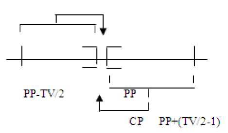
Fig 2. Modification of the data table with threshold value
For eg: let us consider a numerical example, if the image file contains the following pixels
128 300 90 180 20 223 99 TV=4 ε [-2, +1]
Table 1. Modified Bit Plane and data plane
|
CP |
PP |
Range |
BP |
DT |
|
128 |
0 |
(-2,1) |
1 |
128 |
|
300 |
128 |
(126,129) |
1 |
300 |
|
90 |
300 |
(298,301) |
1 |
90 |
|
180 |
90 |
(88,91) |
1 |
180 |
|
20 |
180 |
(178,181) |
1 |
20 |
|
223 |
20 |
(18,21) |
1 |
223 |
|
222 |
223 |
(221,224) |
0 |
- |
CP: Current Pixel PP: Past Pixel
BP: Bit Plane DT: Data Plane
(b).CIELAB
The L * a * b * space consists of a luminosity layer L *, a chromaticity-layer a *, which indicates where color falls along the red-green axis, and a chromaticity-layer b *, which indicates where the color falls along the blueyellow axis. The intermediate variables for converting RGB to CIELAB are as follows.
W = 0.4303*R + 0.3416*G + 0.1784*B(6a)
Y = 0.2219*R + 0.7086*G + 0.0713*B(6b)
Z = 0.0202*R + 0.1296*G+ 0.9393*B(6c)
У
L * = 116( h (—)) -16(7a)
Y s
W У a * = 500( h (—)) - h (-)
WsYs
Y 7
b* = 200( h (-) - h (-))(7c)
YsZs
Where Ys, Ws, Zs are the standard stimulus coefficients.
'h ( q ) = 3 4q , q > 0.0088
<
7.787 q + -6, q < 0.0088
Where ‘q’ is the threshold value, both a *and b * layer contains all color information. [7]
-
V. Proposed Method
In order to conduct the image concerning the compression of the images, the BPT algorithm is used by adopting the following steps:
-
1. Firstly, Integer Wavelet transforms and the Binary plane technique is applied to the source image where two codes are utilized to make bit plane. Code 1 is used to indicate that current pixel is
-
2. Then the difference coding technique is applied where the difference image is created by applying the exclusive OR logic operation between the neighboring pixels in the original image. While, it is observed that the difference can be coded more effectively when the average run length of the black pixels in the original image is greater than the two where the compression is attained due to the correlation between the adjacent pixels in the difference image is reduced when comparing it with the original image.
-
3. Then, the inverse of difference coding technique is applied whose results are then applied to inverse binary plane technique and inverse integer wavelet transform in order to reconstruct the image.
different from the previous pixel and in such situation current pixel is moved to the data table. However, Code 0 is used to demonstrate that the current pixel is similar to the previous pixel and eradicates the storage of current pixel.
The proposed method is applied for three color space domains such as RGB, YCbCr and CIELAB .The method can be followed by the proposed methodology for super resolution image reconstruction which is described in the following steps:
-
> Read a clean I 1 (x,y) , Blurred I 2 (x,y) and
Gaussian noise corrupted I 3 (x,y) LR images.
-
> Apply IWT to all the three LR images and
acquire the low frequency components.
-
> Apply loss less BPT (threshold=0) to these low frequency components and consider the values in the data table.
-
> The result of BPT will be a data planes and Bit planes. Out of three data planes choose two minimum values` of data planes and find the average between them.
-
> The modified data table values along with the bit plane components of I 1 (x,y) are given for the inverse BPT to obtain the modified low frequency components.
-
> Inverse IWT is applied for these components along with the high frequency components of I 1 (x,y).
-
> Finally, Spline based interpolation is applied to obtain a SR reconstructed image.
-
VI. Experimental Results
The proposed method is used to analyze the LIVE image database taking into consideration the effect of blur and noise.
(a) (b) (c)
(d) (e) (f)
Fig 3. Results obtained with the proposed method under different color space transforms (a). Original Image (b). Blurred image (c). Noisy image (d). SR image (RGB) (e) SR image (YCbCr) (f). SR image (CIELAB)
In order to measure the performance of super resolution algorithm, we have used the objective image quality measure such as PSNR and ISNR (Improvement in Signal to Noise Ratio).
-
(a) Peak Signal to Noise ratio:
PSNR = 10log10
255 ?
MSE )
Where mse = у [ f ( i , j ) F ( I , J )] , f(i,j) is the clean image Z N2
and F(I,J) is the SR reconstructed
Image which contains N×N pixels.
-
(b) Improved Signal to Noise ratio:
Z e f ( i , j ) - y ( i , j )]2
ISNR = 10log10 -,j----------------
Z e f ( i , j ) - g ( i , j )] 2
Where i,j are the total number of pixels in the horizontal and vertical dimensions of the image. f(i,j),y(i,j) and g(i,j) are the clean ,degraded and the reconstructed SR images.
(c) Homogeneity [9]
HOM
N - 1
E i, JeN
! , [ f ( x , У ) — f ( i , J )] 2
M
(d) Blocking Effect [10]

(a)
(a)
(b)

(b)
(C)
(d)
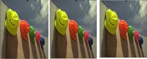
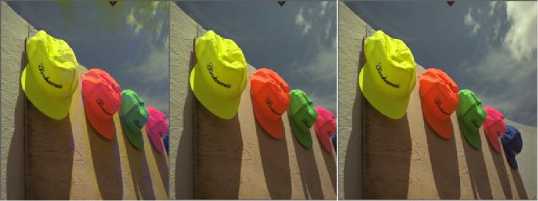
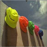
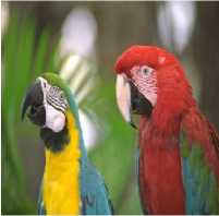
Fig 4: Test Samples taken from LIVE image database (a).Caps (b). Butterfly (c). Parrots (d) Woman
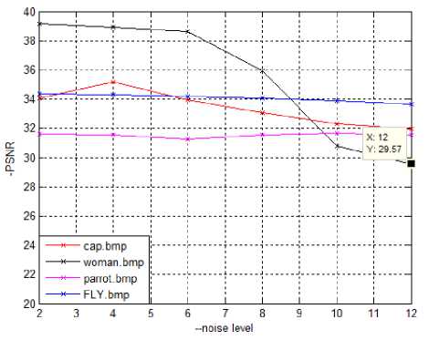
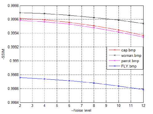
Fig 5. Compression of (a) PSNR and Noise level (b) SSIM and Noise level for Cap, Women, Parrot and Fly.
Table 2: Performance analysis of the proposed method in RGB Space domain
|
Image |
RGB Domain |
||||||
|
PSNR for Blur Image |
PSNR for Noisy Image |
PSNR for Super Resolution Image |
ISNR For Super Resolution Image w.r.t. Noisy Image |
ISNR For Super Resolution Image w.r.t. Blur Image |
Blocking Effect |
Homogeneity |
|
|
Caps |
37.0896 |
33.6841 |
40.9501 |
7.2659 |
3.8604 |
0.0220 |
0.3247 |
|
Butterfly |
36.5199 |
38.557 |
51.2957 |
12.7387 |
14.7758 |
0.0447 |
0.4820 |
|
Parrots |
41.0189 |
39.5232 |
42.2606 |
2.7373 |
1.2417 |
0.0237 |
0.1202 |
|
Woman |
34.349 |
37.0695 |
46.1901 |
9.1206 |
11.8411 |
0.0296 |
0.4213 |
Table 3: Performance analysis of the proposed method in YCbCr Space domain
|
Image |
YC b C r Domain |
||||||
|
PSNR for Blur Image |
PSNR for Noisy Image |
PSNR for Super Resolution Image |
ISNR For Super Resolution Image w.r.t. Noisy Image |
ISNR For Super Resolution Image w.r.t. Blur Image |
Blocking Effect |
Homogeneit y |
|
|
Caps |
37.0896 |
33.6841 |
48.1629 |
14.4788 |
11.0733 |
0.0223 |
0.3276 |
|
Butterfly |
36.5199 |
38.557 |
48.3284 |
9.7715 |
11.8085 |
0.0450 |
0.4709 |
|
Parrots |
41.0189 |
39.5232 |
49.6263 |
10.103 |
8.6074 |
0.0244 |
0.1164 |
|
Woman |
34.349 |
37.0695 |
44.3098 |
7.2403 |
9.9608 |
0.0302 |
0.4128 |
Table 4: Performance analysis of the proposed method in CIELAB Space domain
|
Image |
CIELAB Domain |
||||||
|
PSNR for Blur Image |
PSNR for Noisy Image |
PSNR for Super Resolution Image |
ISNR For Super Resolution Image w.r.t. Noisy Image |
ISNR For Super Resolution Image w.r.t. Blur Image |
Blocking Effect |
Homogeneit y |
|
|
Caps |
37.0896 |
33.6841 |
52.8443 |
19.1602 |
15.7547 |
0.0228 |
0.3247 |
|
Butterfly |
36.5199 |
38.557 |
53.319 |
14.762 |
16.7991 |
0.0452 |
0.4843 |
|
Parrots |
41.0189 |
39.5232 |
52.4374 |
12.9142 |
11.4185 |
0.0244 |
0.1159 |
|
Woman |
34.349 |
37.0695 |
53.1288 |
16.0593 |
18.7798 |
0.0294 |
0.3771 |
-
VII. Conclusions
SR image reconstruction with IWT and BPT is proposed in the present context and a qualitative analysis is evaluated for different test samples taken from the LIVE image database under different color space transforms. From the data obtained we can conclude that the present method in CIELAB domain has shown better results than the other color space transformations. In the paper ‘Binary plane technique for super resolution image reconstruction using integer wavelet transform’ the author proposed a method and compared different methods in gray scale domain which proved to be the best in the paper. The result of Binary plane technique will be a data planes and bit planes. Instead of taking three data planes here we have taken minimum values of two data planes and we have find out average value between them. Due to this PSNR and ISNR values has improved.
A good qualitative analysis is evaluated with above mentioned parameters which are shown in the graphs in figure 5 which are comparison of PSNR and noise level, SSIM and noise level with respect to different images.
It can be known clearly from the above figures that the quality of SR image has great influence under higher noise levels but it doesn’t have a dramatic change when the blur mask size is varied. From this we can conclude that the proposed SR image reconstruction is robust against the blur where as it has a slight variation with noise .The method is computationally efficient since no complicated transforms are involved and the algorithm can be implemented without storing the entire image in memory, which makes embedded implementations easier. This paper can be further extended by considering different fusion algorithms and with different color transformation techniques
References Performance Evaluation of Super Resolution Image Reconstruction using IWT and BPT with Different Colour Transforms
- T. S. Huang and R. Y. Tsai, “Multi-frame image restoration and registration,” Adv. Comput. Vis. Image Process., vol. 1, pp. 317–339, 1984.
- M. E. Tipping and C. M. Bishop, “Bayesian image super-resolution,” Advances in Neural Information and Processing Systems 16, 2003.
- Dr. M.Ashok and Dr. T. Bhaskar Reddy, "Color image compression based on Luminance and Chrominance using Binary Wavelet Transform (BWT)and Binary Plane Technique (BPT)," International Journal of Computer Science and Information Technology & Security (IJCSITS) , vol. 1, no. 2, pp. 2249-9555 , 2012.
- N. Subhash Chandra et al., "Loss Less compression of Images using Binary Plane Difference and Huffman coding (BDH Technique) ," Journal of Theoretical and Applied Information Technology, vol. 3, no. 1, pp. 3-56, 2008.
- P.Ashok Babu,Dr.K.V.S.R.Prasad,” A lossy color image compression using IWT and BPT”,Graphics & Vision Vol:12,Iss:15,2012.
- R.C.Ganzalez “Digital Image Processing”, Pearson Education India.
- Ming-Ni Wu; Chia-Chen Lin; Chin-Chen Chang; , "Brain Tumor Detection Using Color-Based K-Means Clustering Segmentation," Third International Conference on Intelligent Information Hiding and Multimedia Signal Processing, 2007. IIHMSP 2007. vol.2, no., pp.245-250, 26-28 Nov. 2007
- S. Farsiu, M. D. Robinson, M. Elad, and P. Milanfar, “Fast and robust multiframe super-resolution,” IEEE Transactions on Image Processing, vol. 13, pp. 1327–1344, 2004.
- N. Idrissi, J. Martinez, and D. Aboutajdine, “Selecting a discriminant subset of co-occurrence matrix features for texture-based image retrieval,” in Proc. ISVC05, 2005, pp. 696–703.
- Zhou Wang; Sheikh, H.R.; Bovik, A.C.; , "No-reference perceptual quality assessment of JPEG compressed images," International Conference on Image Processing Proceedings. 2002 vol.1, no., pp. I-477- I-480 vol.1,2002.
- Jianchoa Yang,Thomas Huang, “ Image super resolution: Historical overview and future challenges”. www.ifp.illinois.edu/~jyang29/papers/chap1.pdf - United States.
