Platform Screen Doors Enhanced Bus Rapid Transit Intelligent Performance

Author: Chonghua Zhou
Journal: International Journal of Information Engineering and Electronic Business(IJIEEB) @ijieeb
Article in issue: 3 vol.3, 2011.
Free access
It is the last straw to clutch at to solve the urban traffic issue, to develop high-capacity rapid transit and promote transit priority. Characterized by low cost, short construction cycle and flexible development, Bus Rapid Transit (BRT) has been favored by more and more cities in the world. The Platform Screen Doors (PSDs) system is an important component at BRT stations, and it is original motive to be designed to satisfy the growing demand from BRT application to provide increased safety and comfort in the first. With the continual increased demand for BRT intelligent performance, the PSDs system is applied to get Bus Location Information with accurate position of arrival and departure at stop, to provide Real-Time Information (RTI) for BRT passengers using PSDs/GPS compound location technology, to put into practice Bus Fleet Management (BFM). Considering the capability of accurate location, it can be applied to actualize Bus Sign Priority in the future. The authors are luck to take in part the practice of BRT system, especially in the BRT intelligent systems, the papers will introduce upwards application and conceive in detail.
Platform Screen Doors, Bus Rapid Transit, Intelligent Performance, Bus Location Information, Real-Time Transit Information, Bus fleet management, Bus Sign Priority
Short address: https://sciup.org/15013094
IDR: 15013094
Text of the scientific article Platform Screen Doors Enhanced Bus Rapid Transit Intelligent Performance
Published Online June 2011 in MECS
The concept of the PSDs system is not new to metro system and it is fixed at train and subway stations platform edge to screen platform from train. And it can give metro system the following benefits: © Prevent passengers from falling or jumping on the tracks; © allow trains passing through the station at high speed; © reduce draught and air pressure caused by trains; © let the platforms be quieter and cleaner; © allow stations to be air-conditioned at lower cost in hot climate; © prevent people from throwing trash on the tracks and preventing track fires; © increase passengers comfort and average train speed and so on.
Similar requirements arose for BRT, and the PSDs system for BRT is original motive to be designed to satisfy the growing demand from BRT application to provide increased safety and comfort firstly. PSDs are installed at BRT stations platform edge and the system can ensure passengers safety by using a Multi-Level control ideal to open/close the Sliding Panels (SPs) which are an important part of it, when the SPs closing it can screen platform from bus lane, and when the SPs opening passengers can board and alight the bus by aligning with Onboard Passenger Doors (OPDs) location on bus set. With the continual increased demand for BRT intelligent performance, it is utilized to achieve various applications such as getting Bus Location Information, providing Real-Time Transit Information, implementing Bus Fleet Management, and assisting to actualize Bus Sign Priority. The reminder of the article is organized as following: System Architecture of the PSDs system is given in Section 2. Bus Location Information Based on PSDs is stated in Section 3. Real-Time Transit Information for BRT based on PSDs/GPS compound location technology is reported in Section 4. Bus Fleet Management Based on PSDs is paid in Section 5. Bus Sign Priority based on PSDs is conceived in Section 6. Conclusions are given in Section 7.
-
II. S YSTEM ARCHITECTURE
Thomas (2001) viewed BRT is “a rapid model of transportation that can combine the quality of rail transit and the flexibility of buses.” Levinson (2003) given a more detailed definition that “BRT is a flexible, rubber-tired rapid transit mode that combines stations, vehicles, services, running way, and ITS elements into an integrated system with a strong positive image and identity.” BRT as a part of urban public transit system has been more and more recognized and demonstrated in some cities such as Curitiba, Brazil, Colombia, Bogota, Ottawa, Brisbane and so on. The time when BRT at Beijing South-Center Corridor went into full operation in the end of 2005 was marked to express that BRT system had entered china, and in succession other cities opened it. In China, the cites including Beijing, Hangzhou, Changzhou, Chongqing, Jinan, Xiamen, Zhengzhou, Yancheng, Zaozhuang, Guangzhou have operated the BRT system and the cities such as Lanzhou, kunshan and so on are building it, many cities also have completed the BRT planning.
One significant visible distinction of BRT is the use of stations. To a success of a BRT system, the stations need provide a metro-like quality of service while guaranteeing fast bus operational speeds. Passengers will pay fares before entering BRT stations, and as with the metro will enjoy level boarding and alighting. Half-height or fullheight PSDs should be used when possible, and Chonghua Zhou (2010) viewed that the Half-height PSDs system has been used widely in China. Fig.1 shows the application of a PSDs system for BRT in China.
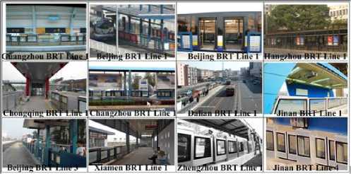
Figure 1. The Application of a PSDs system for BRT in China
The Half-height PSDs system is composed of Sliding Panels (SPs), Fixed Doors (FDs), Base, Drive Mechanism, Suspension and Guidance Agencies, Anti-Pinch Devices and Control System. Chonghua Zhou (2009) explained the elements and the Fig.2 shows the system architecture and components.
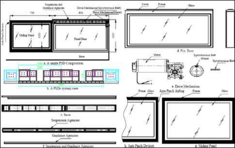
Figure 2. System Frame and Components for PSDs-BRT.
FDs are installed at the stations edge to act as a safety barrier to screen the platform from the bus lane, also as a shelter to protect SPs, Drive mechanism and other electrical elements from external unfavorable factors, and they used to as a holder to locate at one end of the Sliding Panel. And SPs can be driven to flexible move in a track which is limited by Suspension and Guidance Agencies, when SPs opening passengers can alight and board bus by corresponding OPDs, and when SPs closing the PSDs system screens platform from bus lane. The role of Base is to connect with ground-based tightly and it is designed to anti-corrosion and anti-rust characters. Drive Mechanism consists of Motor and Synchronous Belt, and it is designed to long life and smooth transmission. Especially, the Motor which has a small size and simple frame is considered preferentially. Suspension and Guidance Agencies are to act as a role of load-bearing and guiding, different cities have theirs load-bearing ways. The cities which use supporting technology to load-bearing include Hangzhou, Chongqing, Beijing and so on. And cities which use hanging technology to loadbearing such as Jinan BRT Line 1 and Line 2, Xiamen BRT Line 1 and so on. One end of SP has deployed AntiPinch Devices to detect the obstacles, and SP will re-open when Anti-Pinch Devices detect the obstacles and closed again after a pre-configured time delay. The PSDs system has Multi-level Control including System-Control, Platform-Control and Manual-Operation-Control.
To cope with various unexpected events, the PSD system is designed to 3 operation models including emergency operation model (Manual-Operation-Control), non-normal operation model (Platform-Control) and normal operation model (System-Control), and the first priority is given to Manual-Operation-Control, the second to Platform-Control and the third to System-Control. With sensors, drives and electronic controllers, each SP is allowing for automatic operation. System-Control is a control panel is installed each bus for drivers to control the doors open and close, Platform-Control is a local control panel is installed each station equipment room for the station staff to locally control the PSDs system when the System-Control can’t work, and Manual-OperationControl is the push operators for the manually operated SPs when the System-Control and Platform-Control are all invalidation.
In accordance with Fig.3, Control System consists of BRT Center facilities, BRT station facilities and onboard equipment which need deploy an Onboard Infrared Transceiver Device (OITD). The Center facilities consist of a central server, workstations and application software and so on. Station facilities include a PSD Station Controller (PSC), an Industrial Personal Computer (IPC), 12 Door Control Units (DCUs), a Platform Infrared Transceiver Device (PITD) and other facilities.
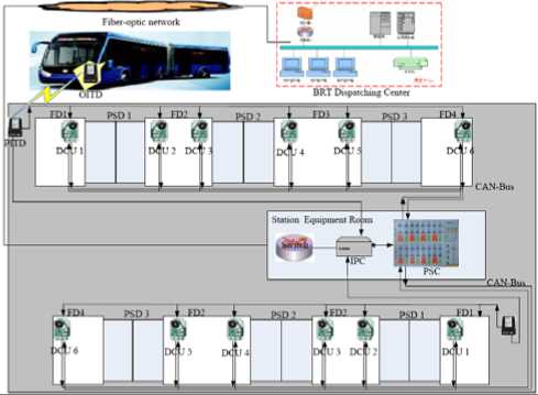
Figure 3. Control system Network topology diagram in Jinan.
The OITD sends out not only the order of open/close but also the data of vehicle character such as vehicle code, the order and data can be transmitted by IR wireless communication. When the PITD receives the order and data, it can control DCUs to open/close SPs, and at the same time it sends the data to the IPC. The PSC acts as 2 roles, one is to control the SPs when System-Control can’t work, the other is to display the status of SPs and report it to the IPC. When the IPC receives the data of vehicle code and status of SPs, it packages the date by installed in the IPC application software to upload to BRT Center through Fiber-optic network immediately. Center server application software is required to not only statistic and clear up the packages, but also form a database table and store in order to call for and print by Center workstations.
-
III. Bus Location Information
At present Bus Location Information is reported by the four principal technologies employed for Automatic Vehicle Location (AVL) System including GPS, Signpost and odometer, Radio navigation and location, Deadreckoning. GPS is the newest of these and is by far the most popular choice for transit agencies implementing new AVL systems today.
With the advantages of low in-vehicle cost, no blind spots or in interferences and repeatable accuracy, Ran Hee Jeong (2004) viewed that the signpost/odometer system was the most common location technology until the advent of GPS. And the Fig.4 shows communication processed of signpost technology.
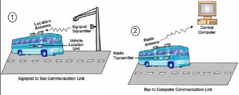
Figure 4. Communication processes of signpost technology.
In a signpost system, roadside proximity beacons are installed along routes. These signposts emit their ID at a certain radio frequency which is detected by the bus as it passes. With the signpost and vehicles ID known, the bus can thus be located to the last signpost passed. If control is centralized, location data is then usually sent from the vehicle to a central location by wireless transmissions. Fig.4 illustrates the communication processes between the transit vehicle, the electronic transmitter, and the central computer.
Compared the above passive identification, the PSDs system locate the bus position is a processes of active identification. Every BRT bus deploys an Infra-Red (IR) transceiver, and when the bus stops at platform within a permissible error distance, bus driver presses the open/close button which can control Onboard IR transceiver to send out an IR signal with order and data of bus ID, Direction etc, and the signal is detected by a Platform IR transceiver mounted at platform edge, then the Platform transceiver reports the signal to the PSDs Controller to open/close Sliding Panels and also reports it to the platform Industrial Personal Computer (IPC) synchronously, and bus ID and Bus Location at stop are usually sent from station to BRT Center via fiber-optic communication. Fig.5 shows the intercommunion between Onboard and Platform IR transceiver. With the advantages of low cost and point-to-point high speed data connection, infrared communication is used widely, particularly in embedded system, but it has some drawbacks, such as short-distance transmission and small-angle (cone angle less 30 degrees).
Once PSDs are fixed, and their size and location have been determined, it can’t be changed. But parking location of bus is flexible at platform, and it is allowed in a certain distance range. Ideal Stopping Position is defined in this article, when the center of OPDs completely is coincident to the center of PSDs and this time the front of bus in the bus lane can touch the location which is called Ideal Stopping Position. According with IR communication characteristic, it requires the drivers to accurately stop the bus at station, and its maximum in the ‘worst cast displacement’ measured from Ideal Stopping Position is 15 centimeters in Jinan. 15 centimeters error to Bus Location Information is very small, so we take the Ideal Stopping Position at every station as the Bus Location Information of arrival/departure at stop in practice.
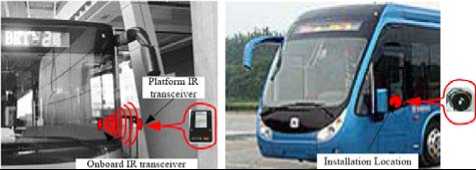
Figure 5. IR transceiver at Onboard and Platform.
Given the following definition: i is representative for bus ID, j is representative for BRT station ID, C j is representative for the Ideal Stopping Position Coordinate (x, y) at station j, A i j is representative for the time of bus i arrives at station j, and D i j is representative for the time of bus i departs at station j, the BRT Center only collects the datum of (i, C j , A i j ) or (i, C j , D i j ) which is real-time reported by IPC. Usually we measure the Ideal Stopping Position Coordinate (x, y) at every BRT station before the BRT system goes into full operation. So only recording the time bus arrival/departure at stop, Bus Location Information of accurate position of arrival and departure at stop is reported by the PSDs system.
-
IV. Real-Time Transit Information
Experience in the initial system
Compared to the traditional Real-time transit information system, the initial system in Jinan is
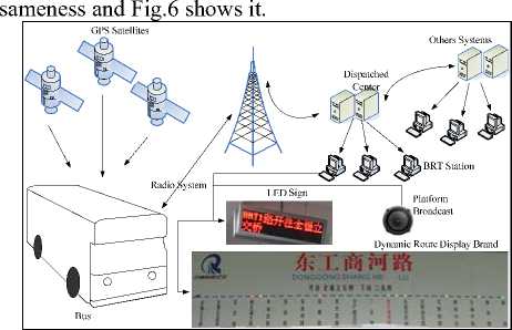
Figure 6. Architecture of the initial system for BRT in Jinan
As the capital city of Shandong Province along the eastern coastline of China, Jinan is the Center of the whole province of politics, economy, culture, science, education, and finance. In direct to response to its rapid economic development and explosive car growth need to strengthen and expand its infrastructure, leaders in the city of Jinan have decide to construct a 135-Km BRT network by 2010, their efforts have leaded to Jinan being named by the Central Government as a BRT Demonstration City in China.
The initial system was built from October 2007 to May 2008, and it covered 3 BRT lines. The infrastructure of the system at stop varies across the city with high quality BRT Center island station and stop poles or bays marked on the roadside. Traditionally the printed information at stop is patchy and inconsistent, BRT Center island station will be provided abundance real-time information and others will be rare. The project consists of: @ 89buses including 53 18-meter-long buses and 36 12-meter-long buses fitted with AVL equipment. ® 3 BRT lines including Line 1, Line 2 and Line 3 covered. And total 25 Center-island stations, of which 5 located Li’shan Road and 21 located Bei’yuan Street, deployed with real-time information display and broadcast facilities. @ total 100 at stop 2-line Light Emitting Diodes (LED) signs, 50 Dynamic Route Display Brands and 100 Broadcast Facilities. @ bus fleet management system for 3 BRT lines.
Onboard computers continuously calculate their position by looking at satellites, and every 20 seconds this datum is fed back to Dispatched Central (DC) computers using the GPRS network. The central computers then check it and match it to the GIS map which is very valuable to monitor operation buses, and it is also dispatched every 20 seconds to the BRT stations using the optical fiber communication network. The Industrial Personal Computer (IPC) of every BRT station receives the bus AVL datum and disseminates it by at stop facilities such as LED signs, Dynamic Route Display Brands and Broadcast Facilities. Each at stop LED sign lists up the next 2 buses which will pass the stations in succession, giving only details of route, destination. And the audio equipment will automatic broadcast the next arrival bus information such as “To Quan’fu Overpass BRT Line 1 will be arrival, please passengers ready for boarding” in Fig.6. Dynamic Route Display Brand (DRDB) is a complex intelligent device to dynamic display all running buses location using yellowing, red and green lights in a Brand which is hanging on the wall at station. Bus location has two states, off stop which is expressed by yellowing light whether vehicle has passed or not the station, at stop which is expressed by red and green lights, red light illustrates that bus has passed the station and green light states that bus hasn’t departure or arrival the station. And it is very valuable to passengers to know that how many buses will arrival and how far every bus is away from the station. A DRDB is hanging on the wall at station of Dong’gong’shang’he in Fig.6, and it shows that the whole BRT Line 1 has 9 running vehicles from Huang’gang to Quan’fu Overpass, of which 4 are off BRT station which are expressed by a yellow light, of which 2 are at BRT station and have passed the station which are expressed by a red light, of which 3 are at BRT station and vehicles hasn’t departure or arrival the station which are expressed by a green light.
Lesson in the initial system
With 19 stations, the first BRT line which starts from Huang’gang and ends Quan’fu Overpass and total 11.5Km has began operation on April 22, 2008, then BRT Line 2 which from Bei’yuan Overpass to Yan’shan Overpass and BRT Line 3 which is from Quan’fu Overpass to Xin’yi’zhuang was opened one after another. The initial system can satisfy the basic requirements providing real-time transit information for BRT passengers, but it is also discovered about weaknesses following as: the first is that it can’t accurately express the states of buses arrival/departure at stop. Usually, we can found a bus has departure at stop but the DRDB shows that the bus is parking at shop, and even the bus is far away the stop and waiting for the front traffic lights dozens of seconds or 1 minute, the DRDB still shows it. The case results that passengers complain the initial system and give a viewpoint of Real-time information system is not real-time. Analyzing the reason following as: @ Usually, the GPS time of the nearest location data from each stop is considered as the arrival time, and the departure time is the GPS time of the first location data appears just after the stopped data with speed zero, so the value of arrival time and departure time is not accurate and the time difference is existing in the system. ® And Ran Hee Jeong (2004) gave the most important reason is that the bus stops are located at the near side of the block and the distance between the bus stop and the intersection is relatively short. Therefore, when the intersection signal is red, the bus tends to stay at the bus stop. It is become the sensor of choice. The second is that the error of missing data of GPS is often found, especially under elevated highway or in bad weather such as rain and snow. And BRT Line 1 is all running under Bei’yuan Street elevated highway which is total 11.5 Km, and BRT Line 2 and Line 3 have part of route under it. So the error seriously impacts the initial system and it results to mess real-time transit services to passengers. For example, without signs indicate that a bus will arrival at stop by forecasting of broadcast or displaying of LED sign and DRDB, but a bus is arrival at stop suddenly and the passengers who are waiting for at stop have to hurriedly board the bus. The case can cause to safety problems easily, so it results that the passengers complain the initial system inevitably.
The upwards explained weaknesses give passengers some troubles really, and it is necessary to combine a certain technology to compensate for inevitable shortcomings of GPS.
System design for the upgrade system
The upgrade system will combine GPS and signpost system or called PSDs system to provide more accurate AVL data and disseminate real-time information to passenger in Jinan future BRT projects. Chonghua Zhou
-
(2010) viewed that a Real-Time Information System for BRT Based on GPS/Signpost Compound Navigation technology and Fig.7 shows the architecture of the upgrade real-time information system for BRT in Jinan.
The upgrade system provides real-time information about bus services via at stop facilities such as LED signs, DRDB and Broadcast. The 4-line LED signs will give information to people waiting at BRT station about the Bus Route, Bus Code, Destination and waiting Distance which is expressed by how many stops is far away from the BRT stations. For example, with the assumption that at the moment bus “i” is arrival at BRT station “j”, the passengers are waiting for bus “i” at station “j+k” and the waiting Distance will display ‘k’, k ^ 0. DRDB and Broadcast facilities are similar to the initial system, and they have explained in this paper.
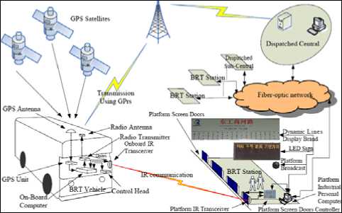
Figure 7. Architecture of the upgrade system for BRT in Jinan
Every 20sedconds DC computers receives bus AVL information which is continuously calculated by OnBoard Computer by looking at satellites using the GPRS data communications network, and they also receive bus arrival/departure real-time information based on PSDs system from stops, then integrate upward 2 kinds of data and dispatch the integrated bus AVL data to every stops every 20sedconds using the optical fiber communication network. Stops receives the integrated bus AVL information and disseminate real-time information to passengers by at stop facilities, and if stops also receive bus arrival/departure information based on PSDs system using Infrared communication, IPC of stops will not only update real-time information to at facilities, but also upload the bus arrival/offsite information to DC computers. So it is a cycle of process between DC computers and IPC of stops.
Data processing for upgrade system
Data fusion technology is good utilized in there. DC processing module acts as a core for integrating GPS data and bus arrival/offsite data based on PSDs system, and processing module at stops also plays an important role in it. Fig.8 explains data processing flow, and T n is expressed as GPS Time of data n.
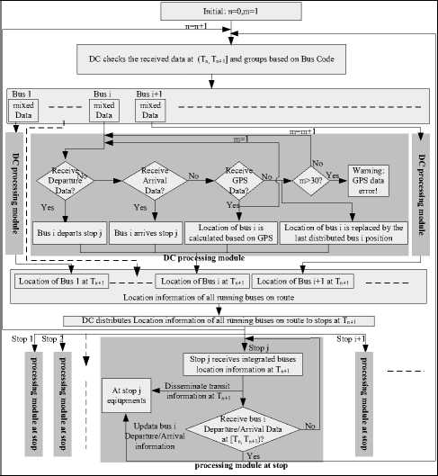
Figure 8. Data processing flow in the upgrade system
Upgrade system implement
The upgrade system was built from April 2009 to October 2009, and it also covered 3 BRT lines and 25 BRT stations. The real-time information system for BRT was notice to procurement on April 14, 2009, and the company of Shandong CVIC Software Engineering got the right to supply and installation the system on May, 2009. The project consisted of: @ 70 buses fitted with AVL equipment. @ 3 BRT lines including Line 4, Line 5 and Line 6 covered. And total 25 Center-island stations, of which 12 located East Er’huan Road, 5 located North Gonng’ye Road and 8 located Middle Ao’ti Road, deployed with real-time information display and broadcast facilities. @ total 75 at stop 4-line LED signs, 175 broadcast facilities; @ bus fleet management system for 3 BRT lines.
By now, the upgrade system operation is stable and it can provide satisfied real-time information about bus services to passenger, particularly accurate information of buses arrival and departure at stops, and it also can make up the drawbacks of failing to disseminate bus location due to missing data of GPS. In spite of all running routes and stations of BRT Line 4 are under East Er’huan Road elevated highway, passengers are satisfy with disseminating real-time transit information via at stop facilities and it is rare to complaint about real-time information services in BRT Line 4, Line 5 and Line 6.
V Bus Fleet Management
System architecture
The concept of Bus Fleet Management System (BFMS) is not new to city public transit, and it is a system which buses in modern fleet are equipped with automatic vehicle location (AVL) devices providing their location information to Bus Fleet Management Center (BFMC) that enables them to determine the current location of buses, estimate time of arrival at bus stops, etc. The key requirement of BFMS is the ability to locate a bus location throughout its travel, to transmit this information back to a BFMC, and then to process this data usefully to ensure you make effective use of your bus fleet. There are several technologies that allow AVL including GPS, Signpost and odometer, Radio navigation/location, Deadreckoning, and usually implement information transmission such as wireless communication and fiberoptic communication. Using GPS and GPRS (General Packet Radio Service) technology, the system of BFMS is becoming increasingly popular in the world today, and in China it is similar for practicing those technologies to BFMS for BRT which is important part of city public transport.
Compared the conventional BFMS using GPS location technology, it will put forward a system which is richly available to accurately locate bus position of arrival/departure at station platform based on the Platform Screen Doors (PSDs) system.
The Architecture of Bus Fleet Management System (BFMS) for BRT is simple, when bus docks and the driver presses the open/close door button which connects with Onboard IR transceiver, the bus ID which is sent by Onboard IR transceiver to the platform IR receiver by IR communication and the platform IPC can record the system clock. Then the datum with bus ID, and recorded time and the ID of the Platform IR transceiver is fed back to Bus Fleet Management Center (BFMC) computers using the Fiber-optic network. According to ID of the Platform IR transceiver matching the value of Coordinate in the BFMC’s database, BFMC could position the bus location and display onto the map to estimate vehicle arrivals, which enhance whole bus management performance. Fig.9 shows the architecture of BFMS for BRT based on the PSDs system.
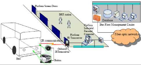
Figure 9. The architecture of BFMS for BRT based on PSDs.
is not rigid. So in China detect incidents to BFMS is difficult and the most task of a BFM operator is to realtime monitor bus fleet, and operating data management etc.
Using the upload real-tine datum from IPCs, the central computers can match the datum to GIS map which is very valuable to monitor operating buses. But in the system the position is only the Platform IR transceivers’ Coordinate and it only can show bus position of arrival/departure at station platform. So a simple figure can illustrate bus real-time position without GIS map such as in Fig.10 which is Buses real-time monitor in Zhengzhou BRT 1line.
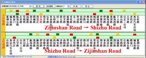
Figure 10. Buses real-time monitor in Zhengzhou BRT 1line.
In Fig.10, the red block expresses that a bus is stopping at station, the green block denotes that a bus depart at station within 30 seconds, and the croci black is represented for a bus depart at station beyond 30 seconds. From the upper figure, it is clear that in the direction form Zi’jin’shan Road to Shi’zhu Road at 10:23:24 on June 2, 2009, there are five buses are stopping at station, five buses have departed at station within 30 seconds, six buses have departed at station beyond 30 seconds. At the same time, there are five buses are stopping at station, five buses have departed at station within 30 seconds, four buses have departed at station beyond 30 seconds in the direction form Shi’zhu Road to Zi’jin’shan Road.
It also is an important management task for establish the database of basic information including BRT lines, bus configuration corresponding bus ID, value of Coordinate corresponding ID of Platform IR transceiver and station etc. Of course, along with the BRT system enlarge increasingly, the database will be updated and maintain unceasingly.
According to the datum (i, C j , A i j ) or (i, C j , D i j ), the system of BFMS can analyze to operating result including dwell time, travel time, average speed and so on, those data is very valuable for BRT operator. Fig.11 shows the dwell time at the station of Hanghai east Raod on May 29, 2009 and the travel time from Hanghai east Road to Shihua Road on June 17, 2009.
Application of BFMS forBRT
BFMS is a system which facilitates the efficient management and scheduling of bus routes to ensure that buses run as per the schedule. A typical task of a BFM operator is to detect incidents (delays, advances, breakdowns,...) by comparing the theoretical timetable of the buses with the real one. In China the bus corporation only can offer to the timetable of the first bus and the last bus for every station, and the time of bus arriving at stop
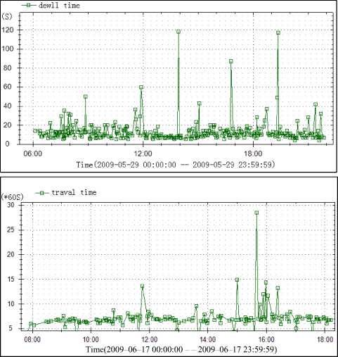
Figure 11. The chart of dwell time and travel time.
Compared popular BFMS, the advantage of the system in this article is cheap cost, better usability. Using the existing station resource of the PSDs system, only to increase simple hardware and software program, the system of BFMS for BRT can build well and rapidly. The deficiency of detect incidents for operator in BFMS application will be improved in the future and perfect application in the system of BFMS will be the direction of effort.
VI Bus Sign priority
Bus Signal Priority (BSP) is a traffic signal enhancement strategy that facilitates efficient movement of buses through signalized intersections. And it has been deployed in many cities around the world, but most BSP systems do not work well in BRT networks with nearside central island stations because of the uncertainty in dwell time. Luckily, the PSDs system is capable to report the accurate time of bus departing at stop for BSP. It will put forward an idea of Bus Signal Priority System for BRT Networks with near-side central island stations.
System Architecture
Detection of buses is accomplished via a compound location technology based on PSDs/GPS. Onboard computers continuously calculate their position by looking at satellites, and every 20 seconds this datum is fed back to BRT Center computers using the GPRS network. And once the PSDs system detects the bus location of accurate position of arrival and departure at stop, it will report to BRT Center computers using Fiberoptic network. BRT Center real-time reports Bus Id and Location to Traffic Control Center, especially when bus departing at stop. According to bus schedule and bus location, the Traffic Control Center decides whether or not to implement sign priority. Green extension and early green are two major priority logics considered for Bus Signal Priority. If deciding to implement BSP, the Traffic Control Center will estimate the spending time from Ideal Stopping Position to near intersection Stopping Line and decide what kind of priority strategy will be actualized. Finally, according with the order form Traffic Control Center, the Signal Controller will implement priority sign to bus. Pic.12 is showing the system frame.
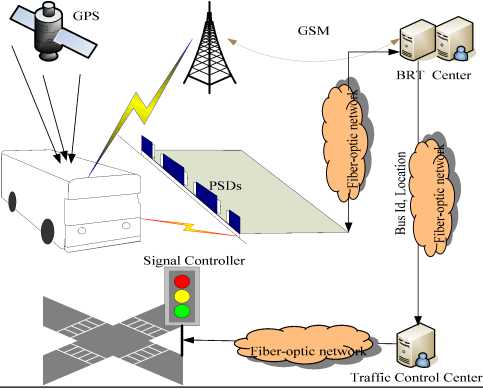
Figure 12. Bus Sign Priority System Architecture
System Analysis
With the advantage of the accurate time of bus departing at stop and estimating the spending time form Ideal Stopping Position to near intersection Stopping Line, the upwards system is capable to accomplish the sign priority for BRT networks with near-side central island stations.
A single near-side central island station need to serve both directions of travel, and to on direction travel it is belong to the kind of near-side bus stop, however to another direction travel it is belong to the kind of far-side bus stop. So the PSDs system can’t report the accurate position before passing intersection for far-side bus stop travel, and it need to add detective facilities to provide the accurate location. It is a deficiency to the Bus Sign Priority system, and it is expect to more and more improve before practicing.
VII Conclusions
This paper introduces some application on Platform Screen Doors in intelligent characteristic such as locating bus position, providing real-time transit information, achieving bus fleet management, and also conceives the architecture of bus sign priority using PSDs. Although the upwards application is not the original aim for Platform Screen Doors which is designed to satisfy the growing demand from BRT application to provide increased safety and comfort. And we wish the applications to facility BRT managers and BRT passengers and expect the applications to be taken into account in the BRT system plan and design.
Acknowledgment
The authors luckily took part in the job which is involving in Jinan BRT system plan, design and building, especially in BRT intelligent system. And we wish to thank Jinan Municipal and Public Utility Bureau and Jinan BRT Corp give the chance to achieve the practice of the BRT system. Meanwhile, we wish to thank Huai’an Hui’min Automobile Accessories Manufacturing Co.,LTD who was supplier of the PSDs system in Jinan, Zhengzhou etc, our work was supported in part by a grant from them.
References Platform Screen Doors Enhanced Bus Rapid Transit Intelligent Performance
- Thomas.E. Bus rapid transit presentation at the institute of transport engineers, Annual Meeting. Chicago, 2001.
- Levinson H.S., Zimmerman S., et al. TCRP Report 90 Bus Rapid Transit – Volume 1, Case Studies in Bus Rapid Transit, and Volume 2 Planning and Implementation Guidelines in Process (TCRP Project A-23), Transportation Research board, National Research Council, Washington, D.C, 2003.
- Chonghua Zhou, Zhizhe Su and Jiuzhou Zhou, “Design and implemention of the Platform Screen Doors system for BRT”, Proceedings of the 10th ICCTP, ASCE, Beijing, 2540-2552, 2010.
- Zhou Chonghua, Zhou Jiuzhou and Zhang Hui, “The system frame and control style of platform screen doors for bus rapid transit.” J. Development & Innovation of Machinery & Electrical Products, 122(4), 138-140, 2009.
- Ran Hee Jeong, “The Prediction of Bus Arrival time Using Automatic Vehicle Location Systems Data”, A Ph.D. Dissertation at Texas A&M University, 2004.
- Chonghua Zhou, Zuogang Gao,“A Real-Time Information System for BRT Based on GPS/Signpost Compound Navigation technology” , Proceedings of the LEITS2010, IEEE, Wuhan, 100-103, 2010.
