PLC controlled substation standby power form the input system

Author: Wang Bao Liang, Wu Liang, Zhang Siqian
Journal: Бюллетень науки и практики @bulletennauki
Section: Технические науки
Article in issue: 6 т.9, 2023.
Free access
This paper introduces the application of Siemens S7-200 PLC in standby power supply. PLC collects the normal running state signal of the primary equipment, which is used as the starting condition and locking condition of the standby power supply automatically input. It realizes different functions through programming to adapt to different running modes. Through PLC and king view in the laboratory, I verified the operation mode. It is also increases the obstacles, enriches the content of the standby self-casting system, and realizes the simulation of the joint adjustment with PLC. It is more obvious to watch the practical application of the stand auto-casting and the diversification of its functions.
Plc back up power, programable logic controller, self-resetting system
Short address: https://sciup.org/14127777
IDR: 14127777 | UDC: 62-53 | DOI: 10.33619/2414-2948/91/36
Резервное питание подстанции, управляемой программируемым логическим контроллером от системы ввода
Представлено применение программируемого логического контроллера PLC в резервном источнике энергии Siemens S7-200. PLC получает сигнал о нормальном состоянии работы одного из первых устройств в качестве условий запуска и условий блокировки для автоматических резервных источников энергии, программируя их для выполнения различных функций в соответствии с различными способами работы. В лаборатории PLC и Mastic King подтвердили, что резервное питание зависит от того, как работает система сброса, и как они взаимодействуют.
Text of the scientific article PLC controlled substation standby power form the input system
Бюллетень науки и практики / Bulletin of Science and Practice
UDC 62-53
The backup power system designed in this paper can guarantee the effect of automatically switching lines to ensure stable power supply in case of power failure. So that there will be no power outage in the substation. The design of the system affects the stable operation of the whole system, which is its core. The relay used in the early stage of our country belongs to the foundation of the system of power backup in substation station. There are complex defects of line. After the long-term work of the system, the probability of failure will be increased constantly. Consuming a great deal of manpower and material resources, the operation of the current power equipment has fallen far behind its needs. Based on the above situation, the research content of this paper, based on PLC as the basis, design a PLC-based standby self-investment system. Through relevant experiments, it can be seen that the back-up self-investment system based on PLC system has a series of advantages such as better safety and higher reliability, and can meet the requirements of control in actual situations [1].
With the continuous development of relay protection, the standby power supply has also been continuously developed and optimized. From the initial electromagnetic type, until now the microcomputer type, its development speed is fast. The initial electromagnetic type of selfpropelled equipment is mainly composed of the following parts, which are time, intermediate and low voltage relays. The staff can easily realize the operation of wiring, and the maintenance process is simple. Because of the above advantages, it has been widely used in various fields. At the same time, electromagnetic relay has the following defects, such as its large size leading to storage difficulties, short use time, slow running speed and other defects. After the optimization and development, the transistor — type equipment appeared. The emergence of this type overcomes the above mentioned defects such as large size, and its function has not been improved. In the actual situation of the project, there may be power failure caused by power failure, so the use of backup power supply is needed to ensure the smooth use of the entire power supply, which greatly improves the reliability of the whole system power supply process. The principle of backup power is simple and the cost is lower. Therefore, it has been widely used in various fields. The most common means of power generation in our country are thermal power generation. Therefore, the reliability of power supply process should be ensured. Therefore, the existence of backup power supply system can better improve this effect [2].
Research and application of automatic input device based on microcomputer standby power supply if there is a failure of the power supply circuit, resulting in a power failure, then the existence of the backup power supply system, will avoid the occurrence of this phenomenon. The self-propelled system has the effect of minimizing losses. The backup power supply has the following functions, such as automatic and rapid load switching, to ensure the smooth running of the circuit. This backup power supply is called an APD device. The continuous development of this device has also played a role in promoting the social economy.
Single bus section operation mode, in most of the application of large factories, then the use of PLC-based standby power source system, can greatly improve its reliability. In the last century, most APD devices were realized by relay, but there were many defects, such as more electric shock and lower service life, which led to the elimination of relay quickly. The development of integrated microcomputer APD device makes it adapt to the development of The Times and play its important effect. Compared with the traditional relay, the development of the new integrated microcomputer APD device has the following advantages: the first point is that the device is intuitive and simple. Its small volume, occupy a small space, at the same time for the data can be real-time view effect. Not only that, but you can also adjust the size of the run data. Second, the device has high reliability. Electromagnetic compatibility technology can greatly improve the reliability of the effect. At the same time, the combination of new anti-electromagnetic and PC devices, including digital filtering technology on the software, can reduce the probability of failure. The third feature is the high degree of intelligence of this device. Have a good ability to adapt. The fourth point is that the device has better comprehensive capacity. The device has two functions of networking and off
— networking. Is monitored by the master station when connecting to the network. Functions can be automatically completed when the system is disconnected from the network. Even if a fault occurs, the system reliability will not be reduced. The core of this device is the CPU. CPU functions can achieve the effect of BZT logic. Compared with the previous mechanical and electrical room equipment, its information processing speed is faster, while the memory function is stronger, the connection is relatively simple. By using BZT logic, the previous wiring debugging process is eliminated. Microcomputer BZT can play a comprehensive logic judgment effect; better solve the previous electric shock with bad defects. Can increase the size of the correct movement accuracy. This device can also carry out error correction query, once the error situation, the system can automatically deal with and eliminate interference, avoid the production of wrong action.
The main work of this paper Combined with the development status of the automatic input device of standby power supply at home and abroad and the background significance of the research, to understand the development prospect of the automatic input device of standby power supply and the structure and function principle of the standby power supply, understand the implementation of the programming logic of the automatic input device of standby power supply and the method of application. Application of Siemens series PLC in school laboratory to realize the control of standby power brake input [3].
Automatic input of standby power supply scheme Power supply scheme requirements the step-down substation of the factory is powered by line 1 and Line 2, and the power supply 1 and 2 are not started together. The capacity of Line 1 and line 2 of the transformer is the same and the capacity of line 2 is dark standby for each other. They are all equipped with current velocity break and overcurrent protection devices. In normal operation, the two power cables run separately. If an accident occurs in a circuit, the automatic input device of the standby power supply first cuts out the circuit breaker on the circuit, and then connects the low-voltage side bus circuit breaker. In this way, the normal line supplies power to all the loads on the buses in section I and II.
The BZT device can display the function of information in real time and has a good humancomputer interaction effect. The recording of information facilitates the operation of post-accident analysis. Microcomputer BZT is similar to theory. , can improve the quality of microcomputer BZT without using electromagnetic relay [4].
In practice, the APD device needs to meet the following conditions in order to be effective: for the APD device, it needs low voltage or no voltage to work. It is necessary to ensure that the power failure time of the device is short to improve the effect of self-starting. Allowing only one action at a time reduces the possibility of persistent failures. If used for many times, serious accidents will occur. In case of loss of voltage of working power supply, the APD device needs to delay the function of switching the circuit breaker of working power supply. The setting of this function can effectively avoid the back-up power supply.
Even if the fuse is blown, or the circuit breaker is tripped, the usual power supply is removed, but the APD device does not perform any operation. Perform this operation only when there is no voltage or current on the incoming line side. Standby voltage when there is no voltage or current, no operation is performed. This equipment needs to be equipped with the following two devices, which are low-voltage starting module and no-current detection starting module [5]. The removal time of external faults should be less than the delay time of the APD device.
To complete the effect of the action logic, you need to use the configuration permit condition and the locking condition to achieve. If it is through the secondary circuit connection, then it will not be able to complete the effect. First of all, it is necessary to charge the action logic, and then determine the allowed and locked conditions. If it is determined to meet the conditions, the corresponding action behavior will be carried out.
The charging logic is equipped in the software of the corresponding backup switching device. Compared with the previous pulse closing relay, it has a better functional effect. There will not be multiple actions of the backup automatic switching device. Although the above operations are properly solved according to the principle that the input of the standby locking contact is set as the pulse input, the standby device needs to be manually reset after the standby action, and manual operation or the corresponding protection device locks the standby action, which increases the operating procedure and the possibility of error for the operator [6].
Power supply scheme operation mode for the operation mode of substation, different analysis should be carried out according to the actual situation. In normal circumstances, there are three types of automatic input modes for checking standby voltage in open-loop substations. The first is the way of running the double bus. If any bus loses voltage and no current occurs at the same time, it is necessary to judge whether part of the load is lost according to the size of the actual power and then relevant judgment. The operation of cutting out the original power supply line. The second way is to fully reveal the nail open ring way. At this time, the load is fed through the incoming line B. It has been found through testing that there is no voltage in the bus bar of the substation and no current in the incoming line B. Incoming line A and B call by open-loop mode, and the automatic input switch changes accordingly. The working principle of both is the same: for this device, there is only one input mode, and once the input mode is changed, the reliability and stability will be reduced [7]. Line 1 and Line 2 use the room running in series or, for both transformers, the capacity size is the same. Dark devices for each other.
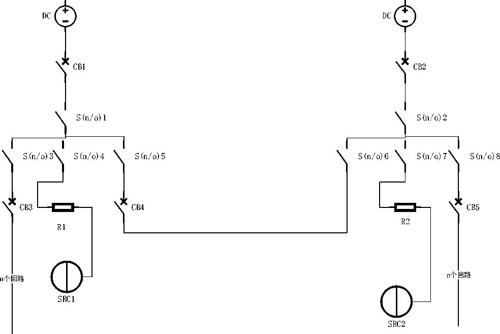
Figure 1. Schematic diagram of the main circuit
PLC type and model selection PLC is a variety of complex, mainly Siemens, Mitsubishi, Toshiba, etc., but can produce a set of equipment and a complete variety of mainly Siemens, Mitsubishi PLC. The PLC model selected by this system is S7-200 226, and its physical picture is shown in Figure 2.
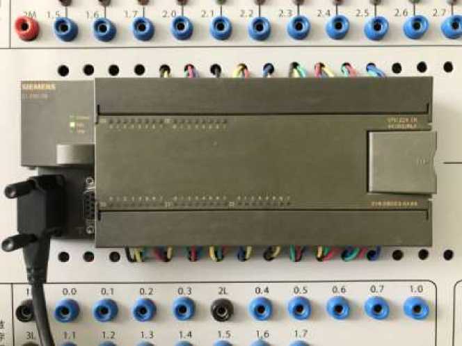
Figure 2. Actual picture of the S7-200
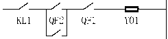
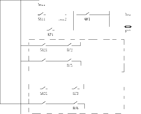
PLC output with circuit breaker controller the switching and closing control of circuit breakers QF1, QF2 and QF3 are divided into manual mode and automatic mode, which are switched by SA11, SA21 and SA31 respectively. No matter in manual mode or automatic mode, one circuit breaker QF1, QF2 and QF3 is locked but cannot be closed, so as to ensure that the two power supplies do not run in parallel, as shown in the Figure.
SA12, SA22 and SA32 are the manual station control switches of QF1, QF2 and QF3 respectively, while KC1, KC2, KC3 and KC4, KC5 and KC6 are the partial and closing relays respectively. KP1 and KP2 are the protective relay outlets of main transformer 1 and main transformer 2 respectively, and KP3 is the relay protection outlet of the bus block circuit breaker. KL1, KL2 and KL3 are anti-jump relays.
When the SA31 control switch is in the automatic position, the standby power automatic input device is in operation. In the manual position, the standby power input device automatically exits the operating state. When the standby power automatic input device is in operation, if QF1 trip, the control loop of QF3 knows that the auxiliary normally closed contact of QF1 is closed.
When QF2 is in the closed state, the closing coil Y03 of QF3 can be powered to close QF3, and the standby power supply is put into use. On the other hand, if the QF2 trip, the backup power will also be put into use.
FU1
FU2
QF1
FU3
SA11
SA12
KL1
KL1
QF3

LD1

LD2
SA11
KC1
R
KC4
SA11
R
SA12
YR1
SA11
KP1
SA21
KC2
KC5
SA31
KC3
Figure 3. Circuit breaker control schematic diagram
I/O allocation Table
Table
I/O ALLOCATION TABLE
|
input |
output |
||
|
Start/stop |
I0.1 |
Running indicator light |
Q0.0 |
|
QF1switch |
I0.2 |
Loss of voltage light on line 1 |
Q0.1 |
|
QF2switch |
I0.3 |
Loss of voltage light on line 2 |
Q0.2 |
|
QF3switch |
I0.4 |
Normal light on line 1 |
Q0.3 |
|
QF4switch |
I0.5 |
Normal light on line 2 |
Q0.4 |
|
QF5switch |
I0.6 |
||
|
Loss of pressure on line 1 |
I0.7 |
||
|
Loss of pressure on line 2 |
I0.8 |
||
|
Line 1 is normal |
I0.9 |
||
|
Line 2 is normal |
I1.0 |
||
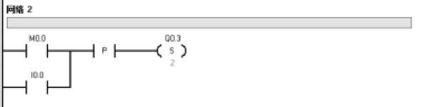
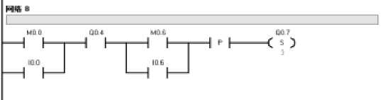
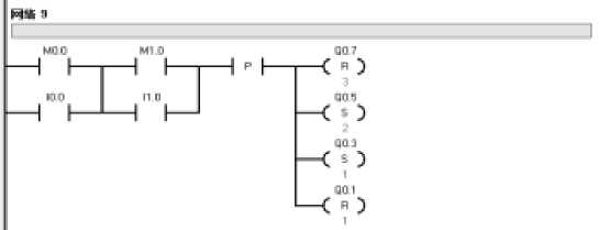
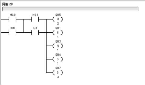
Programming ladder diagram: Input signals are directly used to control output signals, and several intermediate links, auxiliary components and auxiliary touch points are used to add memory, linkage, and interface functions. This can satisfy the relationship between the system exit signal and the input signal, as well as the chain and mutual locking requirements.
-
1. M0.0 is the intermediate relay, I0.0 is the conduction, P is the rising edge detection instruction, P detects the rising edge, Q0.3, Q0.4 is set to 1, line 1 normal indicator light.
-
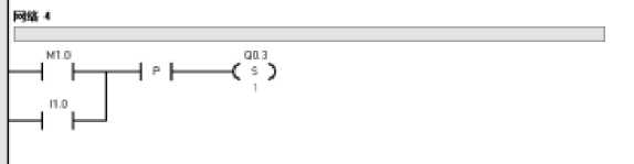
2. I1.0 is conductive, P detects rising edge, Q0.3 is set to 1, line 1 resumes normal operation, Line 1 normal indicator lights up.
-
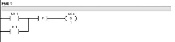
3. I1.1 is conductive, P detects rising edge, Q0.4 is set to 1, line 2 runs normally, Line 2 normal indicator lights up.
-
4. I0.0 is conductive, P detects the rising edge, Q0.5, Q0.6 set 1. QF1 switch coil starts

-
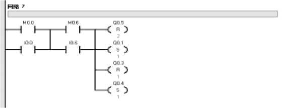
5. Press I0.6, Q0.5, Q0.6 to 0, Q0.1 to 1, Q0.3 to 0, and Q0.4 to 1. The voltage loss indicator of line 1 is on, the QF1 switch coil is off, and the normal indicator of Line 1 is off.
-
6. Set the Q0.4 switch coil to 1, press I0.6, P detects the rising edge, the voltage loss indicator of line 1 is on, and the normal indicator of line 2 is on.
-
7. Line 1 is normal, QF3 switch coil is set to 0, QF1 switch coil is set to 1, Line 1 voltage loss indicator light is on, Line 1 normal indicator light is off.
-
8. If QF1 and QF2 of line 1 are set to 0 (fault), then line 2, QF3, QF4 and QF5 are set to 1 (normal operation), Line 1 will turn on the voltage loss light and line 2 will turn on the normal operation light. The second row of trapezoids is self-locking.
Debugging and simulation Connect cables to the CPU226, input/output module and power supply based on the Tables. Connect the computer to CPU226Obtain communication, compile and download ladder diagram to PLC, debug and simulate the backup system. Open the program status monitoring to observe whether the ladder diagram written can meet the requirements of the subject.
In the process of debugging and simulation, according to the debugging function of PLC and the simulation function of Kingview, line 1 and line 2 are represented by keys and lights. When PLC starts to run, line 1 lights up. When there is a problem on line one, line two lights up.
PLC and Kingview link screen the first is the basic function of the standby power supply. If line 1 of the main power supply fails, the system automatically switches to line 2. Realize the application of standby power supply.
Conclusion Through the study of the function and structure of the automatic input device of standby power supply, this paper understands the background and research direction of automatic input of standby power supply. In addition, the comparison of the remote standby automatic power input device and the microcomputer standby automatic power input device lets us understand how to better choose the corresponding device to make the research more effective and economical. Finally, this paper introduces the relevant knowledge of Siemens S-200PLC, and successfully realizes the automatic input of standby power supply through PLC and realizes the simulation and joint adjustment with Kingview.
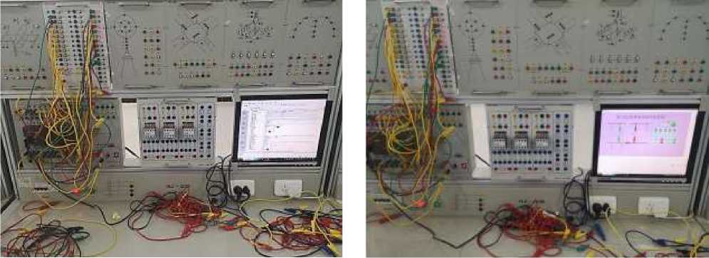
Figure 4. Debugging and simulation
Figure 5. Normal operation
Based on the above research and design, this paper draws the following conclusions:
-
1. This paper compares various automatic input devices of standby power supply, analyzes the outstanding advantages and shortcomings of various devices, so as to better use various devices to control the standby power supply.
-
2. Through the introduction of automatic input of standby power supply and various aspects of expansion and supplement, understand the typical connection of automatic input of standby power supply and its implementation. In this paper, various conditions of voltage loss are analyzed, so that the backup power can be correctly and successfully invested.
References PLC controlled substation standby power form the input system
- Xu Zhengya. Automatic Device of Power System. Beijing: Water Resources and Electric Power Press, 1992. P. 28-30.
- Wang Shaolong, Hu Yunfang Standby energy self - injection system based on PLC // Tianshui Power Supply Company. 2016. №9. P. 328-263.
- Mei Hongtao. Principle and Application of Programmable Controller (PLC). Beijing: China Water Resources and Hydropower Press, 1998. P. 198-200.
- Chen Yu, Duan Xin. Fundamentals and Programming Skills of Programmable Controller. Guangzhou. 2002. P. 56-71.
- Chen Maoying. Application of backup power automatic input device // Guangdong Electric Power News. 2007. V. 20. №12. P. 138-140.
- Tang Meifang, Liu Zhongyong. Standby power supply automatic input device application // Power Automation Equipment. 2006. V. 26. №11.
- Xiang Xianzheng, Chen Hui, Li Zhen, Chen Yulan. Automatic input strategy of microcomputer backup power supply suitable for security control system // Automation of Electric Power Systems. 2006. V. 30. №4. P. 66-67.
