Possibility of unification of radiation resistance requirements for spacecraft with different operating conditions

Author: Nazarenko A.A., Maksimov I.A., Kochura S.G.
Journal: Siberian Aerospace Journal @vestnik-sibsau-en
Section: Aviation and spacecraft engineering
Article in issue: 1 vol.24, 2023.
Free access
During the period of active lifetime in different types of orbits, spacecraft (SC) are exposed to various factors of outer space. The main factor influencing the performance of radio-electronic equipment is the ionizing radiation of outer space. The main effect associated with the impact of ionizing radiation of outer space on the SC (dose effects), in its physics, is determined by the radiation dose absorbed in the components of the electronic component base (ECB) and construction materials during the entire lifetime. This effect explains the failures in the operation of radio-electronic equipment due to the degradation of the parameters of the used ECB products and materials. Calculation of levels of exposure to absorbed doses depending on various parameters of the orbit is a necessary and important task for ensuring the SC functioning during a given lifetime, since calculations of radiation resistance are based on the levels of exposure in orbit. Carrying out calculations taking into account the SC and onboard equipment (OBE) design features is the key problem from the point of view of minimizing mass protection and the scope of tests of critical ECB products. In addition to taking into account the design of the SC and the OBE, an important aspect when calculating the radiation resistance is taking into account the relative position of the OBE in the SC. The paper considers the possibility of unifying the requirements for radiation resistance for SC with dif-ferent operating orbits and lifetime, as well as the possibility of carrying out a unified calculation without taking into account the design features of the SC, OBE and relative position within the SC.
Spacecraft, dose effects, onboard equipment, lifetime, unification
Short address: https://sciup.org/148329680
IDR: 148329680 | UDC: 621.38 | DOI: 10.31772/2712-8970-2023-24-1-126-135
Text of the article Possibility of unification of radiation resistance requirements for spacecraft with different operating conditions
Modern experience of space technology development is characterized by an increase in the functional complexity of OBE, an increase in the active lifetime and autonomy, together with a decrease in weight and size characteristics. The most important element hindering the successful implementation of the tasks set and the minimization of the weight and size characteristics is the impact of space factors on the SC onboard systems. The key space factor is the ionizing radiation of outer space [1–10].
Carrying out calculations of radiation resistance is a very labour-intensive and time-consuming task, since it implies a whole range of works. The calculation must take into account all the parameters that affect the radiation resistance - the orbit of operation, the design features of the SC and OBE. Taking into account the current trend towards the transition to serial production of SC in the shortest possible time, the issue of unifying requirements without carrying out calculations on radiation resistance for a specific SC becomes relevant in the case of borrowing OBE developed for one project and adapted to the composition of another SC.
Methodology for calculating the radiation resistance of onboard equipment (dose effects and bias effects)
At the moment, most calculations of the OBE radiation resistance are carried out using specialized software, taking into account the division into 3600 rays. Typical levels of absorbed doses inside the OBE, taking into account protection by the design of the OBE and SC for a specific location of ECB products, vary from 5 to 100 krad. The levels of radiation resistance of ECB products are also in the range from 5 to 100 krad.
At the same time, the level of resistance of the active ECB products used must exceed the level of exposure with a certain safety factor. This provision is fundamental in the formation of conclusions about the radiation resistance of OBE.
The basis for any technical expertise on the admission of the OBE as a part of SC to flight tests are the positive conclusions made in the Calculation (Analysis) of the radiation resistance of the OBE.
The main stages in the calculation:
-
– preparation of the SC model for calculation taking into account the specific location of the OBE;
-
– integration of the 3D model of the OBE with the SC model;
-
– calculation of the exposure level for ECB products using software for a specific operating orbit: the absorbed dose is calculated at the selected point of the device (the location of ECB products), based on the thickness of the mass protection for each of the rays in the angle of 4π sr when the space is divided into 3600 rays. Depending on the complexity of the device, the calculation is carried out for 10–30 points for each board. The degree of detail of the board used for the calculation and the illustration of the calculation are shown in fig. 1;
-
– calculation of safety factors for each ECB product (by dividing the resistance level of the ECB product by the calculated impact level);
-
– formation of a list of ECB products for testing flight lots. Tests are carried out for ECB products with Sf ˂ 3 or ECB products, for which a discrepancy between the level of resistance according to technical specifications (TS) was revealed (It is important: in accordance with the NTD RF, tests should be carried out precisely for those manufacturing dates of ECB products, with which the flight instrument will be completed);
-
– carrying out tests and adjusting the calculation of durability.
Since the methodology for calculating the OBE radiation resistance involves dividing the space into 3600 rays, and the total equivalent protection for a point is calculated taking into account the protection for each ray, accordingly, it is necessary to re-calculate the OBE radiation resistance for each specific case, even with a slight change of SC and OBE layouts.
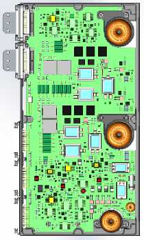
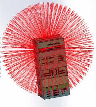
Fig. 1. Calculation illustration
Рис. 1. Иллюстрация расчёта
Requirements for a SC
The impact model, in terms of radiation resistance, depends on the orbit of operation and the active lifetime of the SC; besides, for SC developed in the interests of the state corporation for space activities “Roscosmos”, the requirements are set in accordance with the impact model set out in NTD RF. Requirements for commercial SC are determined by the customer and may differ from the model set out in the NTD RF, as they are set in accordance with with international standards – impact model AE8-max, AP8-min [11–15].
A comparative graph and dependences of the absorbed dose on the value of equivalent protection for the operating orbits of commercial SC and SC developed in the interests of the state corporation for space activities “Roscosmos”, as well as for SC with different orbits and active lifetime, is shown in Fig. 2 and in table 1–3.
Commercial SC. active lifetime 15 years, GSO
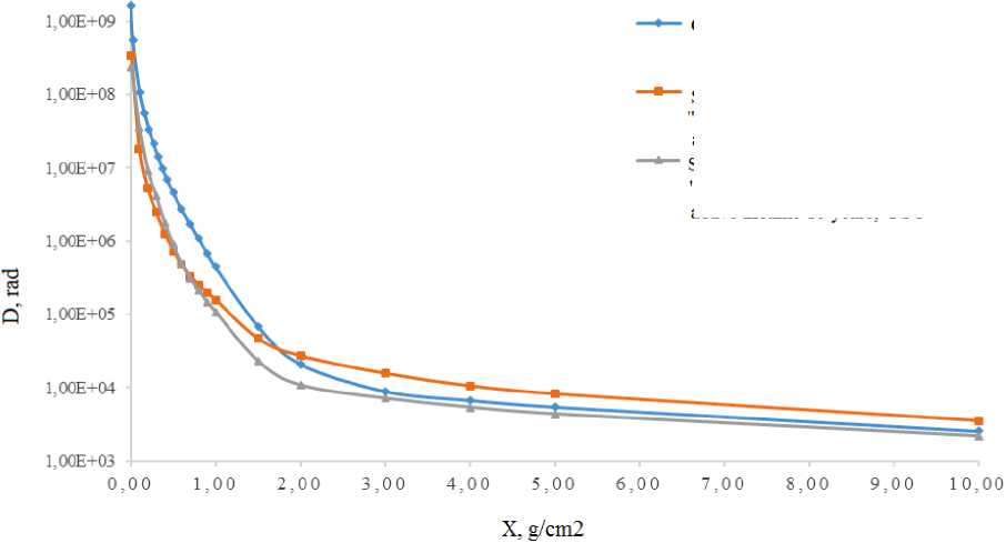
1 g/cm2 = 3.7 mm Al
SC in the interests of 'Roscosmos" andMoDRF, active lifetime 10 years, HEO SC in the interests of "Roscosmos" and MoD RF, active lifetime 10 years, GSO
Fig. 2. Comparison graph
Рис. 2. Сравнительный график
Table 1
Dependence of the absorbed dose on the value of protection for 10 years of active lifetime (taking into account the stage of final elimination) for SC in the interests of the state corporation for space activities "Roscosmos" in a 4π sr solid angle behind a spherical shield (according to the NTD RF)
|
Protection value, g/cm2 |
Absorbed dose, rad (total dose) |
|
0,01 |
2,32E+08 |
|
0,1 |
3,60E+07 |
|
0,2 |
9,14E+06 |
|
0,5 |
8,78E+05 |
|
0,8 |
2,10E+05 |
|
0,9 |
1,47E+05 |
|
1 |
1,08E+05 |
|
5 |
4,36E+03 |
|
8 |
2,76E+03 |
|
9 |
2,44E+03 |
|
10 |
2,18E+03 |
Table 2
Dependence of the absorbed dose on the value of protection for 15 years of active lifetime for commercial SC in a 4π sr solid angle behind a spherical shield (NASA model AE8, AP8)
|
Protection value, g/cm2 |
Absorbed dose, rad (total dose) |
|
2,70E-03 |
1,66E+09 |
|
2,70E-02 |
5,48E+08 |
|
1,08E-01 |
1,08E+08 |
|
4,86E-01 |
4,97E+06 |
|
6,08E-01 |
2,62E+06 |
|
6,75E-01 |
1,91E+06 |
|
1,01E+00 |
4,15E+05 |
|
1,08E+00 |
3,10E+05 |
|
1,15E+00 |
2,33E+05 |
|
1,55E+00 |
5,93E+04 |
|
2,03E+00 |
1,99E+04 |
|
2,09E+00 |
1,76E+04 |
|
2,16E+00 |
1,60E+04 |
|
2,23E+00 |
1,46E+04 |
|
2,70E+00 |
9,95E+03 |
|
2,97E+00 |
9,00E+03 |
|
3,24E+00 |
8.21E+03 |
|
3,51E+00 |
7,59E+03 |
|
4,05E+00 |
6,64E+03 |
|
5,40E+00 |
5,02E+03 |
|
1,35E+01 |
1,76E+03 |
Table 3
Dependence of the absorbed dose (for spherical protection geometry) on the value of protection for 10 years of active lifetime for SC in the interests of the state corporation for space activities "Roscosmos" in a 4π sr solid angle (in accordance with the NTD RF)
|
Protection value, g/cm2 |
Absorbed dose, rad (total dose) |
|
0,01 |
3,40E+08 |
|
0,1 |
1,82E+07 |
|
0,2 |
5,20E+06 |
|
0,3 |
2,47E+06 |
|
0,4 |
1,27E+06 |
|
0,5 |
7,39E+05 |
|
0,6 |
4,79E+05 |
|
0,7 |
3,36E+05 |
|
0,8 |
2,53E+05 |
|
0,9 |
1,96E+05 |
|
1 |
1,58E+05 |
|
1,5 |
4,67E+04 |
|
2 |
2,71E+04 |
|
3 |
1,56E+04 |
|
4 |
1,05E+04 |
|
5 |
8,21E+03 |
|
10 |
3,53E+03 |
Analyzing the data presented in fig. 2 and in tables 1–3, we can conclude that in the protection range of 0.01–1.5 g/cm2 (0–5.5 mm Al), the exposure levels according to the international model AE8, AP8 (commercial SC) several times (from 3 to 6) exceed the impact levels according to the NTD RF model for GSO and HEO, respectively. In the protection range of 2–10 g/cm2 (7.4–37 mm Al), the requirements for the HEO operating orbit according to the NTD RF are 1.5–2.5 times higher than those for commercial SC. Accordingly, in order to unify the requirements for radiation resistance for the above SC, it is necessary to form requirements based on the maximum values of absorbed doses for all protection ranges:
0.01–1.5 g/cm2 – model AE8, AP8 (commercial SC);
2–10 g/cm2 – model of NTD RF (SC in the interests of the state corporation for space activities “Roscosmos”, HEO, 10 years of active lifetime).
Unified requirements (envelope) are presented in fig. 3 and table 4.
It is permissible to use the requirements for SC in the interests of the state corporation for space activities “Roscosmos”, HEO, 10 years of active lifetime as unified requirements for displacement effects.
Commercial SC, active lifetime 15 years, GSO
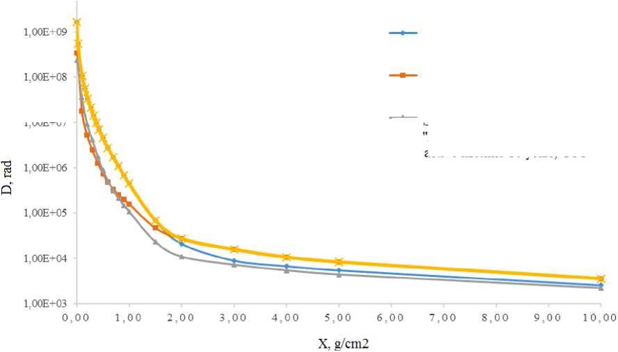
1 g/cm2 = 3,7 mm Al
Fig. 3. Unified requirements
SC in the interests of "Roscosmos" and MoD RF, active lifetime 10 years, HEO
“* SC in the interests of ’Roscosmos" and MoD RF, active lifetime 10 vears, GSO
Рис. 3. Унифицированные требования
Table 4
The dependence of the absorbed dose on the value of protection (unified for the “Express-RV” SC, “Express-AMU4” SC, “Yamal-501” SC, “Luch-5VM” SV) in a 4π sr solid angle
|
Protection value, g/cm2 |
Absorbed dose, rad (total dose) |
|
0,0027 |
1,66E+09 |
|
0,0270 |
5,48E+08 |
|
0,108 |
1,08E+08 |
|
0,162 |
5,66E+07 |
|
0,216 |
3,36E+07 |
|
0,270 |
2,14E+07 |
|
0,324 |
1,42E+07 |
|
0,378 |
9,72E+06 |
|
0,432 |
6,85E+06 |
|
0,500 |
4,62E+06 |
|
0,600 |
2,73E+06 |
|
0,700 |
1,71E+06 |
|
0,800 |
1,08E+06 |
|
0,900 |
6,88E+05 |
|
1,000 |
4,46E+05 |
|
1,500 |
6,94E+04 |
|
2,000 |
2,71E+04 |
|
3,000 |
1,56E+04 |
|
4,000 |
1,05E+04 |
|
5,000 |
8,21E+03 |
|
10,000 |
3,53E+03 |
Unified calculation
In view of the differences in the SC design and layout, the unification of the requirements for radiation resistance is not a guarantee of compliance with the resistance of the OBE as a part of a particular
SC. The only option in which the OBE can be borrowed to another SC without a full-fledged radiation calculation for a specific SC is when a simplified calculation was carried out for the OBE, as a result of which positive results were obtained.
There are several ways to carry out a simplified calculation:
-
1) calculation using a simplified SC model and unified requirements (for OBE located inside an unpressurized instrument compartment): a detailed 3D model of the OBE and a simplified SC model (in the form of a box with a minimum equivalent protection that is the same on all sides (0.8 mm Al) are used, without taking into account the specific location of the OBE and shielding of the adjacent OBE).
Advantages: the calculation can be used for any SC.
Disadvantages: ECB products with a high level of resistance (about 100 krad) are required, the amount of radiation tests of ECB products is increasing (in relation to the calculation carried out taking into account the actual design of the SC and shielding of the adjacent OBE, since the number of ECB products with Sf ˂ 3 will increase), if the level of resistance of ECB products is insufficient to ensure Sf ≥ 1, the OBE will need to be modified and the mass will need to be increased (which could have been avoided if the shielding of the adjacent OBE and the actual design of the SC had been taken into account). This method of calculation is applicable only for newly developed OBE, since the development of design documentation immediately takes into account the necessary modifications to the design of the OBE, taking into account the placement of the least resistant ECB product, and local protection is established at the level of ECB products.
In addition, the current lack of a sufficient number of types of ECB products with a radiation resistance level of about 100 krad will lead to the need to increase the minimum equivalent protection several times;
-
2) without taking into account protection by the SC design using unified requirements (for the OBE located outside the unpressurized instrument compartment): the calculation is carried out using the detailed 3D models of the OBE without taking into account any protection from the SC.
Advantages: the calculation can be used for any SC.
Disadvantages : ECB products with a high level of resistance (200–300 krad and more), or an increase in the thickness of the OBE own body (5 mm and more) and installation of local protection on ECB products are required; the amount of tests increases (in relation to the calculation carried out taking into account the protection provided by the SC design and shielding of the adjacent OBE, since the number of ECB products with Sf ˂ 3 will increase), if the level of resistance of ECB products is insufficient to ensure Sf ≥ 1, the OBE will need to be modified and mass will need to be increased (which could have been avoided if the shielding of the adjacent OBE and the SC design had been taken into account);
-
3) taking into account the protection from the side of the landing plane (for OBE located outside an unpressurized instrument compartment): a detailed 3D model of the OBE and the minimum equivalent protection from the side of the landing plane are used for the calculation.
Advantages: the calculation can be used for any SC.
Disadvantages: ECB products with a high level of resistance (100 krad and higher), or an increase in the thickness of the OBE own body and the installation of local protection on ECB products are required; the amount of tests increases (in relation to the calculation carried out taking into account the protection provided by the SC design and shielding of the adjacent OBE, as the number of ECB products with Sf ˂ 3 will increase), if the level of resistance of ECB products is insufficient to ensure Sf ≥ 1, the OBE will need to be modified and the mass will need to be increased (which could have been avoided if the shielding of the adjacent OBE and the design of the SC had been taken into account).
Conclusion
The analysis made showed that the unification of the requirements for radiation resistance (dose effects, displacement effects) is possible, however, given that for different spacecraft the requirements differ up to 6 times, and also in accordance with regulatory documents, the criterion for testing ECB products is to ensure a threefold safety factor. will lead to an unreasonable increase in the scope of testing and mass protection.
Borrowing OBE without a full calculation of radiation resistance for a specific SC is possible only if a simplified calculation was initially carried out using unified requirements (without taking into account the real placement of OBE in the SC). At the same time, regardless of how the resistance calculation was carried out, it is necessary to test flight lots. In accordance with the NTD RF, tests must be carried out precisely for those manufacturing dates of ECB products with which the flight instrument will be completed (taking into account the permissible frequency).
Simplified calculation has the following disadvantages:
-
1. ECB products with a high level of resistance are required (100 krad or more, which is not always feasible).
-
2. The scope of testing significantly increases (since the number of ECB products with Sf ˂ 3 increases), while the total cost of testing all ECB products significantly exceeds the cost of a full-fledged calculation for a specific SC.
-
3. If the level of resistance of ECB products is insufficient, it will be necessary to modify OBE and increase the mass to introduce additional radiation protection (which could have been avoided if the shielding of the adjacent OBE in the real SC design had been taken into account).
-
4. In order to minimize the mass of the OBE and the costs of testing ECB products, it is preferable to calculate the resistance of the OBE taking into account the protection by the elements of the actual design of the OBE and SC, the specific location of the OBE and ECB products, and the requirements for given orbits of functioning and active lifetime.
References Possibility of unification of radiation resistance requirements for spacecraft with different operating conditions
- Maksimov I. A. [Problems of ensuring the reliable functioning of modern spacecraft in condi-tions of the destabilizing effect of space factors and man-made factors]. Vestnik SibGAU. 2010, No. 4(30), P. 100–102. (In Russ.).
- Maksimov I. A., Kochura S. G. Issledovanie vliyaniya faktorov kosmicheskogo prostranstva i tekhnogennykh faktorov na kosmicheskie apparaty, razrabotka metodov i sredstv zashchity [Study of the influence of space factors and man-made factors on spacecraft, development of methods and means of protection]. Krasnoyarsk, 2011, 182 p.
- Ivanova T. A., Pavlov N. N., Reyzman S. Ya. [Monitoring of the radiation situation in the geo-stationary orbit at the maximum of the 23rd solar cycle] Materialy 3-y Vserossiyskoy nauchnoy kon-ferentsii “Fizicheskie problemy ekologii” [Materials of the 3rd All-Russian Scientific Conference “Physical Problems of Ecology”]. Mosсow, 2001, Vol. 6, P. 8. (In Russ.).
- Vlasova N. A., Getselev I. V., Ivanova T. A. [Monitoring the radiation situation on high-apogee spacecraft]. Materialy V mezhotraslevoy nauchno-tekhnicheskoy konferentsii “Elektrizatsiya kosmich-eskikh apparatov i sovershenstvovanie ikh antistaticheskoy zashchity kak sredstva uvelicheniya nadezh-nosti i srokov aktivnogo sushchestvovaniya” [Materials of the V interdisciplinary scientific and technical conference “Electrification of spacecraft and improvement of their antistatic protection as a means of increasing the reliability and terms of active existence”]. Korolev, 2002, P. 1 (In Russ.).
- Sosnovets E. N., Panasyuk M. I., Vlasova N. A. [Modeling and monitoring of the radiation situ-ation in the Earth's magnetosphere on high-apogee spacecraft]. Materialy konferentsiya po fizike solnechno-zemnykh svyazey “Solnechno-zemnaya fizika” [Materials conference on the physics of so-lar-terrestrial relations “Solar-terrestrial physics”]. Irkutsk, 2002, Vol. 2 (115), P. 1 (In Russ.).
- Maksimov I. A., Prokop'ev Yu. M., Khartov V. V. [Creation of a monitoring system for external influencing factors arising from the operation of the spacecraft]. Materialy Chetvertogo mezhdunarod-nogo aerokosmicheskogo kongressa [Materials of the Fourth International Aerospace Congress]. Moscow, 2003, P. 1 (In Russ.).
- Novikov L. S. Sovremennoe sostoyanie i perspektivy issledovaniy vzaimodeystviya kosmicheskikh apparatov s okruzhayushchey sredoy. Model' Kosmosa, vos'moe izdanie. Tom 2. Vozdeystvie kosmicheskoy sredy na materialy i oborudovanie KA [Current state and prospects of re-search into the interaction of spacecraft with the environment, Introduction, Model of the Cosmos, eighth edition. Vol. 2. The impact of the space environment on materials and equipment of the space-craft]. Moscow, 2007.
- Rantanen R. O., Bareiss L. E., Ress E. B. Determination of Space Vehicle Contamination. Proc. Of Centre Natianal D’Etudes Spatiales Symphosium on Evaluation of Space Environment on Materi-als, held at Toulouse. France. P. 211–232.
- Testoyedov N. A., Kochura S. G., Maksimov I. A. [Study of the mechanisms and levels of the impact of the space environment on the spacecraft]. Vestnik SibGAU. 2016, No. 6, P. 77–90 (In Russ.).
- Tverskaya L. V., Balashov S. V., Veden’kin N. N. et al. [Outer radiation belt of relativistic electrons in the 23rd solar cycle minimum]. Geomagnetizm i aeronomiya. 2012, Vol. 52, No. 6, P. 779–784 (In Russ.).
- Xapsos M. A., O’Neill P. M., O’Brien T. P. Near-Earth Space Radiation Models. IEEE Trans. Nucl. Sci. 2013, Vol. 60, No. 3, P. 1691–1705.
- Sawyer D. M., Vette J. I. AP-8 Trapped Proton Environment for Solar Maximum and Solar Minimum. NASA-TM-X-72605. NSSDC/WDC-A-R&S 76-06, 1976.
- Vette J. I. Trapped Radiation Environment Model Program (1964–1991). NSSDC/WDC-A-R&S 91-29. November, 1991.
- Vette J. I. The AE-8 Trapped Electron Model Environment. NSSDC/WDC-A-R&S 91-24, 1991.
- Ginet G. P., O’Brien T. P., Huston S. L. et al. AE9, AP9 and SPM: New Models for Specify-ing the Trapped Energetic Particle and Space Plasma Environment. Space Sci. Rev. 2013, Vol. 179, P. 579–615.
