Построение системы управления мгновенными значениями тока статора в электроприводе переменного тока

Автор: Мещеряков Виктор Николаевич, Воеков Владимир Николаевич
Журнал: Вестник Южно-Уральского государственного университета. Серия: Энергетика @vestnik-susu-power
Рубрика: Электромеханические системы
Статья в выпуске: 2 т.14, 2014 года.
Бесплатный доступ
Объектом исследования является энергосберегающая система частотного управления двигателем переменного тока, выполненная на базе инвертора тока с релейными регуляторами тока статора. Область применения - подъемно-транспортное оборудование, а также механизмы циклического действия общепромышленного назначения. Применение современной элементной базы, позволяющей использовать новые алгоритмы управления, расширяет функциональные возможности систем управления двигателем переменного тока и помогает добиться энергосбережения. Разработан и исследован преобразователь частоты с автономным инвертором тока (АИТ) на базе IGBT-транзисторов с дополнительными отсекающими диодами и буферными конденсаторами. Этот преобразователь позволяет получить выходное напряжение, близкое к синусоидальному. Проведен комплекс исследований разработанных систем управления двигателем переменного тока. Они включают в себя аналитические исследования и математическое моделирование. Результаты моделирования совпадают с аналитическими исследованиями и показывают, что система соответствует предъявляемым требованиям и обладает улучшенными энергетическими показателями.
Автономный инвертор тока, релейный регулятор тока, система управления, преобразователь частоты, электропривод переменного тока
Короткий адрес: https://sciup.org/147158261
IDR: 147158261 | УДК: 62-83:621.314.26
Developing a system of instantaneous stator current values control in an AC electric drive
The given research paper sees into AC energy saving electric drive control system, based on current inverter with a relay regulator of stator current. Application field of this system is lifting and handling machines and also special purpose industrial vehicles. Using recent hardware components, which provides new control algorithms application, extends electric drive control system functionality and advances energy loss enhancement. Frequency converter with self-commutated current inverter (SCSI) based on IGBT-transistors contains additional cutting diodes and buffer condenser blocks is developed and researched. Frequency converter ensures a near-sinusoidal output voltage curve form. Researches of designed AC electric drive control systems were performed, comprising analytic survey and mathematic simulation. Analytic surveys and simulation results confirm and show that control system meets specified requirements and is high-performance power system.
Текст научной статьи Построение системы управления мгновенными значениями тока статора в электроприводе переменного тока
Using variable-frequency AC electric drives on general and special purpose industrial vehicles, for example, in metallurgy, brings about a considerable energy saving effect and functionality enhancement.
Asynchronous electric drive systems equipped with frequency converters (FC) based on selfcommutated voltage inverters (SCVIs) have currently become most widespread in low and average power vehicles. However, an electric drive supply voltage rippling is considered to be one of the main drawbacks of above mentioned inverters. As a rule, FCs based on self-commutated current inverters (SCCIs) are used in high-power electric drives [1]. Improvement of FCs based on SCCIs due to replacing of conventional thyristors with high-frequency switchers provides the following advantages in comparison with FCs based on SCVIs:
-
– elimination of additional recuperation blocks;
-
– loss reduction and electric drive lifetime increase due to high quality of power supply provided at 3–4 kHz frequency of the inverter switcher commutation [2, 3].
The given research paper sees into a new type of a frequency converter based on power IGBT transistors with a relay current regulator which provides supply voltage quality improvement for AC variablefrequency control electric drives.
Control system description
To develop a current inverter, a conventional IGBT transistor bridged with a bypass diode, and a cutting diode in series (Fig. 1) can be used as a gate-controlled element with unilateral conductivity. Using a cutting diode (D) enables the three-phase inverter to avoid flow of instant values of compensating currents via the bypass diodes.
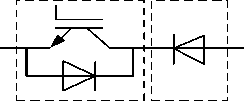
Fig.1. IGBT transistor connected in series with cutting diode
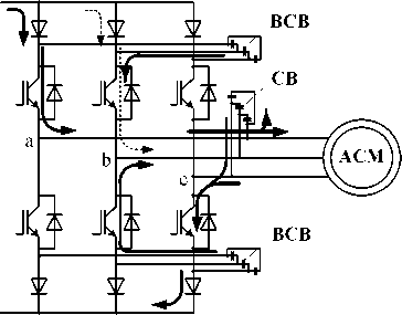
The power circuit of a frequency converter with a self-commutated current inverter contains additional cutting diodes (CD) in series with IGBT transistors (TB), and additional buffer condenser blocks (BCB). The condenser battery (CB) is connected to inverter ports. Fig. 2 shows AC electric drive control system with frequency converter (FC) based on selfcommutated current inverter (SCCI) equipped with relay current regulator (RCR).
In variable-frequency control systems of AC electric drive with the relay current regulator, instantaneous phase current values of a stator are formed, with these signals being compared with the measured values of these currents from current sensors (CS), and in case if difference of currents exceeds its threshold value the relay regulator activates a corresponding arm of circuit. The flowchart of the on-off hysteresis regulator of current is given below (Fig. 3).
The basic principle behind the electric drive work is as follows. Amplitude I 1 and frequency f 1 of the electric motor current are converted by a signal converter into three sinusoidal signals i 1 ′ A , i 1 ′ B , i 1 ′ C correspondingly according to the given equations:
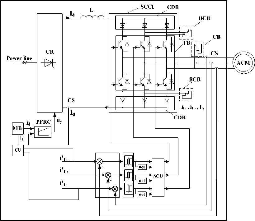
Fig. 2. A block diagram of an AC electric drive with FC based on CSI equipped with a relay current regulator (RCR). SCCI – self-commutated current inverter; CDB – cutting diode block; SCU – switchers control unit; CR – controlled rectifier; TB – transistors block; CS – current sensors; CB – condenser battery;
BCB – buffer condenser blocks; CU – conversion unit; MB – multiplication block; ACM – AC motor
i i a = I isin ( 2 n f . ■ t ) ;
1-1 . 2n I
4b = I isin l 2 n f. ■ t + -3 I ;
The above mentioned sinusoidal signals for phase currents of the electric motor i i A , i iB , i iC reach the input terminals of the relay regulators (RR), where the (1) difference between preset and actual magnitude of instantaneous phase currents A ii A , A ii B , A iic is given:
i i c = I i sin l 2 n f. ■ t
—
2 n । J ,
where t – the given time.
A i i A = A i i A — i i A ;
A i i B = A i i B — i i B ; (2)
A i i C = A i i C — i iC .
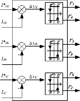
Fig. 3. The on-off hysteresis regulator
The current status of the output terminals of relay regulators Q A , Q B , Q C is determined by the following algorithm:
|
Q a = i, если A i i a |
h " 2; |
h qa = 0, если A i i a < 2; |
|
|
Q b = i, если A i i b |
> h • 2; |
h Q B = 0, если A i i B < 2; |
(3) |
|
Q c = 1, если A i ic |
> h ; 2; |
h Q c = 0, если A i ic < 2, |
where h – modulus of hysteresis, which is assumed to be 0,5 % from the amplitude of the rated current of the electric motor.
High and low bound values of the current limiting the magnitude of the current of each correspon-
Электромеханические системы ding phase of the electric motor at any arbitrary moment of time are determined on the basis of the modulus of hysteresis.
On getting the current signal I 1 the multiplier unit generates the direct current magnitude id . A proportional-plus-integral action controller maintains the current magnitude id proportional to the current signal I 1 .
The relay current regulator produces an actuating signal received by the current inverter, the power output terminals of the latter being connected to the stator windings of the asynchronous drive. The internal contour of degeneration feedback of the stator current is formed applying a relay current regulator and current sensors in each phase correspondingly. This type of contour supports high precision of a given instantaneous phase current value maintenance of the stator in case if high commutation frequency is provided. The characteristic feature of a system based on a selfcommutated current inverter is an invariable current flow through the power load.
Current flow circuits in inverter components are shown below. Fig. 4a illustrates the way of instant current values distribution in inverter switchers, with one top switcher open in phase b, and two bottom ones open in phases a and c. When switching the regulator of current in phase a, the bottom switcher of this phase interrupts the circuit while the top one opens (Fig. 4b). In this case phase a capacitive current consumed by the filtering condenser battery, and its direct current are commensurable quantities. Therefore, when currents in the two considered phases are of the same polarity, the circuit in phase b formed by a current curve is interrupted, because Id = ia + ib, where ia – current in an inverter phase a, ib – current in an inverter phase b and, as it is noted above, ia = Id then ib ^ 0 . As a result smoothness of current components in the inverter phases gets broken (Fig. 5).
The characteristic functioning feature of a selfcommutated current inverter with a relay current regulator is commutation frequency instability during the main current harmonica formation. A switcher frequency commutation increase results in a condenser battery consumption increase of a blind current. In this case Id current value is too low to maintain the demanded value of output current in the inverter phase (Fig. 5). To overcome the problem the Id current value is intentionally raised by 5–7 %, with the inverter switcher frequency commutation slightly increasing,
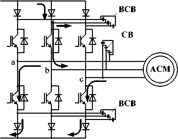
Fig. 4. Current distribution in inverter phases: а – before phase A switching; b – after phase A switching
b
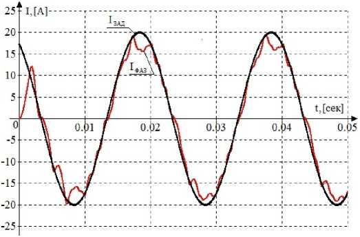
Fig. 5. Inverter output current curve with line disturbances for one phase with I d value insufficiency
I,А 900
-900
-200
-300
-400
-500
-600
-700
-800
0 -100
0.0050.010.
.0150.020
.0550.060.0650.070.0750.080

.0250.030.0350.040 0450.050.
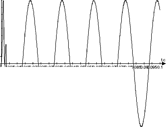
Fig. 6. Inverter output current curve in good functioning variable-frequency control system based on SCCI
but the preset value of the coefficient of nonlinear output current sinusoidal distortions of the inverter ensured.
Buffer condensers (BCB) are used as additional source of the deficiency phase make up supply that improves the smoothness component of the output currents of the supplying electric drive inverter (Fig. 6). Oscillatory character of the output current high-frequency component can be accounted to energy exchange between the electric drive stator winding and the condenser battery (CB) filtering high-frequency components of currents at the frequency converter outputs, and also to the phases mutual influence at commutation. After opening one of the next inverter switchers, the buffer condensers (BBK) are charged ensuring current flow in all inverter activated phases.
Additional cutting diodes (DB) prevent the buffer condensers discharge on the other two inverter phases. Introducing buffer condensers into an inverter allows avoiding current smoothness component interruption in inverter phases, that improves the stator current curve form (Fig. 6).
The equivalent transfer function of the contour with a relay regulator can be described by an aperiodic link with a fast time constant [4].
The noncompensated time constant T is accepted to be the value inversely proportional to the frequency of Pulse-Width-Modulator (PWM) comparison operation. This frequency depends on the module of the hysteresis, with the latter being estimated in accordance with stator current maintenance precision and stability of the control system functioning, as follows:
2I1н т = , where – effective stator current rated value
T = —1— = 0,0003 s .
ц 3000
The contour in question supports high precision of a given instantaneous phase current value maintenance of the stator which is defined by the preset acceptable value of a current deviation A (applied A = 0,05 ) and fast response. The transfer function of the closed loop can be described as follows:
W ( p ) = tp^ ■ <6)
Conclusion
The considered control system of instantaneous stator current values ensures a near-sinusoidal output voltage curve form.
The system presented can be integrated into a standard variable-frequency control system of an AC electric drive, for example, into a system with an external contour of speed regulation.
The considered frequency converter based on a self-commutated current inverter with a relay current regulator makes it possible to develop a close-loop two-channel frequency control system of an asynchronous drive with speed and torque regulating, providing energy saving electric drive behavior.
Электромеханические системы
Список литературы Построение системы управления мгновенными значениями тока статора в электроприводе переменного тока
- Sokolovsky G.G. Elektroprivody peremennogo toka s chastotnym regulirovaniem [Electric drives with frequency control]. Moscow, Academia Publ., 2006. 259 p.
- Meshcheryakov V.N., Bezdenejhnykh D.V., Bashlykov A.M., Abrosimob A.C. [AC electric drive control method], Patent 2456742 RU. MPK N02R25/02., 2012.
- Meshchceryakov V.N., Abrosimov A.S. [Analysis of electric drive control systems based on the autonomous current inverter with relay controls current and voltage regulator relay with smoothing capacitor filter]. Electrotechnical complex and controlling systems, 2011, no. 3, pp. 64-68. (in Russ.)
- Meshchceryakov V.N. Sistemy elektroprivoda peremennogo toka s chastotno-tokovym releynym upravlenie [AC drive system with variable-current control relay]. Lipetsk, LF. MIKT Publ., 2011, pp. 34-44.
