Power analysis of toroidal core electromagnetic energy harvesters for transmission lines

Author: Balci M.S., Dalcali A.
Journal: Инженерные технологии и системы @vestnik-mrsu
Section: Электротехнологии и электрооборудование
Article in issue: 4, 2023.
Free access
Introduction. As the need for energy increases, energy harvesting methods have also been intensively researched. Energy harvesting techniques which are a way of converting low amounts of energy from the environment into electrical energy can be used to meet the energy needs of low-power electronic devices and sensors. The increase in such sensors and devices with low power consumption also makes energy harvesting techniques more important. One of these harvesting techniques is energy harvesting from electromagnetic fields, which is obtained from transmission lines. Aim of the Article. The article is aimed at developing an effective electromagnetic energy harvester from energy transmission lines for unmanned aerial vehicles.
Energy harvesting, toroid core, transmission line, finite element analysis, electromagnetic harvesters
Short address: https://sciup.org/147242370
IDR: 147242370 | UDC: 621.315.05 | DOI: 10.15507/2658-4123.033.202304.599-611
Анализ мощности электромагнитных сборщиков с тороидальным сердечником для линий электропередачи
Введение. В связи с ростом потребности в энергии интенсивно исследуются и методы ее сбора. Одним из таких методов является сбор энергии от электромагнитных полей, получаемых от линий электропередач. Преобразование малых количеств энергии из окружающей среды в электроэнергию может использоваться для работы маломощных электронных устройств и датчиков. Цель статьи. Разработать эффективный сборщик электромагнитной энергии от линий электропередач для беспилотных летательных аппаратов.
Text of the scientific article Power analysis of toroidal core electromagnetic energy harvesters for transmission lines
An increase in industrial development, driven by technological advancements, as well as the rapid population growth have led to a continuous rise in energy demand. This escalating consumption pattern brings about various challenges on supply security and quality issues in energy. To ensure energy supply security, it may be necessary to diversify energy consumption and increase production levels. However, it is crucial to emphasize that the establishment of power lines alone is insufficient; continuous monitoring, maintenance, and repair are equally critical aspects in guaranteeing the 600 Электротехнологии и электрооборудование supply security. A significant number of transmission lines are situated in rural areas, far away from residential zones, making it essential to address certain environmental conditions while monitoring these lines. Factors such as snow and ice accumulation have the potential to affect the distance of lines from the ground and impose substantial loads on supporting poles. Consequently, these situations pose significant challenges and necessitate a meticulous attention to prevent any disruptions [1]. This underscores the vital importance of diligent monitoring and swift intervention to ensure the smooth and uninterrupted functionality of power lines.
In order to monitor the lines, various sensors and equipment are employed to track the parameters such as conductor temperature, inclination angle, and line deflection [2]. Due to the significant difficulty in accessing transmission lines, providing a continuous power supply for these sensors and equipment is a crucial challenge. Therefore, energy harvesting methods can be particularly beneficial, especially for the systems that operate with low-power levels.
Energy harvesting can be defined as the process of obtaining a small amount of electrical energy from various available energy sources in the environment. The energy harvesting process can be accomplished by utilizing diverse resources such as solar, wind, electric fields, and magnetic fields. In monitoring energy transmission lines, electromagnetic energy harvesters can be employed thanks to their several advantages, including their ability to operate as long as there is current in the lines, simplicity of structure, and low maintenance costs [3]. Electromagnetic energy harvesters can possess various geometric shapes of cores, such as toroidal, U-shaped, or triangular. The performance of electromagnetic field energy harvesters is dependent on several variables, such as magnetic material, line current, the number of windings, and core geometry.
In this study, the design, analysis, and experiments of electromagnetic energy harvesters were conducted using toroidal cores of different sizes and magnetic permeabilities for energy transmission lines for unmanned aerial vehicles (UAVs). The designed harvesters were initially analyzed using the Finite Element Method (FEM) and subsequently tested in an experimental setup. Within the scope of the study, the mutual and self-inductance values obtained from each harvester were determined theoretically and through FEM simulations. Additionally, the voltage induced by the harvesters was calculated theoretically and measured in an experimental environment. Furthermore, measurements were taken at different resistance values to determine the maximum power transferred to the load, and the highest power was calculated by curve fitting.
Literature Review
Electromagnetic energy harvesters operate based on the fundamental principles of transformers, deriving energy by inducing voltage from electromagnetic fields referred to as a waste on energy transmission lines. There have been various studies in the literature aimed at enhancing the performance and efficiency of electromagnetic energy harvesters. In a study investigating the influence of core materials, electromagnetic energy harvesters designed using different materials such as ferrite, nanocrystalline, and iron powder were tested with a 5 A line current. The results revealed that the harvester with a nanocrystalline core exhibited the highest power density [4]. However, the data obtained from this single-line current study remains limited. In a similar study, various electromagnetic energy harvesters employing ferrite, nanocrystalline, and iron powder were tested, and the harvester with a ferrite core yielded the highest power at a 15 A line current [5]. When considering these two studies together, it can be observed that a higher power was obtained from the harvester with a ferrite core in one study, while the harvester
♦v? ИНЖЕНЕРНЫЕ ТЕХНОЛОГИИ И СИСТЕМЫ Том 33, № 4. 2023 with a nanocrystalline core yielded the higher power in the other study. The reason is that although the ferrite core has lower relative permeability than the nanocrystalline core, it is much better than the nanocrystalline core in terms of saturation. Therefore, the selection of magnetic material for an energy harvester design should be based on specific conditions of transmission lines. In another study, the idea of short-circuiting the windings was proposed to prevent core saturation, and a parallel switch was added for this purpose. As a result, the harvested power level was increased by 27% [3]. In a different study testing air-core harvesters of various sizes, a power output of 6.32 mW was achieved at a magnetic flux density of 21.2 μT and a frequency of 60 Hz [6]. In a study focused on the design and testing of harvesters recommended for UAVs to be used for monitoring energy transmission lines, a harvester located 2 cm away from a 10 A and 240 V line achieved an induced voltage with the amplitude of 10 V [7].
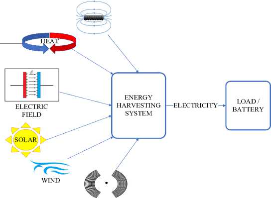
Energy harvesting is the process of collecting energy from available sources in the surroundings and converting them into electrical energy. It can be used as an alternative method to meet energy needs of low-power electronic devices and sensors. Particularly in recent years, with an increasing demand for energy and a growing interest in alternative energy sources, energy harvesting methods have been intensively researched. The energy harvesting process can be performed using various sources such as vibration, wind, solar, heat, magnetic field, and electric field, as shown in Figure 1. Each of these sources used in energy harvesting has its own advantages and disadvantages depending on their respective application areas [8].
MAGNETIC FIELD
VIBRATION
F i g. 1. Energy harvesting systems
Energy harvesting can be achieved through solar energy, which is a renewable energy source. Solar energy has various advantages such as being environmentally friendly, having minimal panel maintenance costs, and being durable [9]. However, the efficiency of these cells varies depending on the type of material [10]. Energy harvesting from solar energy can only be performed under the sunlight. Additionally, even during daytime, the efficiency of energy harvesters significantly decreases if the weather is cloudy.
602 Электротехнологии и электрооборудование
Another method utilized in energy harvesting is the generation of energy through heat. This method can be employed on any system or device that produces heat, particularly those utilized in industries. There has been a significant increase in the importance of energy harvesting through heat due to the substantial rise in temperature differentials observed in both natural and industrial environments. Thermoelectric generators capable of harvesting energy from heat are advantageous in that they do not possess any moving parts, thus requiring minimal maintenance and exhibiting long lifespans [11]. However, the efficiency of thermoelectric materials is very low and their costs are high [12].
Wind energy has become quite popular in recent years. Wind energy harvesters can be classified into rotating blade harvesters and wind-induced vibration harvesters. Harvesting process of the rotating wind harvesters is done with rotating elements, making the system complex and the maintenance costs high. The wind-induced vibration harvesters, on the other hand, are specifically designed on a structure to allow wind to blow and cause mechanical vibration. The kinetic energy generated by wind is, firstly, converted into vibration energy. Then, the vibration energy is further converted into electrical energy through an electromechanical conversion mechanism [13–15]. The wind energy harvesters, like solar ones, depend on the weather conditions. While these harvesters are efficient in windy conditions, their efficiency decreases when there is no wind.
Vibration-based energy harvesters convert vibrations into electrical energy. Vibration, being easily found in the environment, is one of the most suitable sources for energy harvesting. Particularly, since solar and wind energies are dependent on the weather conditions, vibration energy emerges as an alternative to these sources. However, it can be said that continuous and regular vibrations are necessary for these harvesters to be efficient. There are three different conversion mechanisms, namely piezoelectric, electrostatic, and electromagnetic. Among these mentioned methods, the most common and efficient one is the piezoelectric conversion mechanism thanks to its various advantages, such as its being the simplest one and having a high power density [16; 17].
The technique for electric-field energy harvesting is based on the fundamental principle of circular propagation of an electric field when a specific voltage is applied to a conductor. This emitted energy can be harvested via capacitive displacement current flowing from the conductor to the ground. For this purpose, the current needs to be diverted to flow from a load [18]. The most significant advantage of harvesting energy from electric fields is that it does not require a current flow in the line and provides ease of installation. The disadvantages of these harvesters are their large size and need for short-circuiting in certain cases [19]. The presence of electric fields around power transmission lines under open-circuit conditions, their independence from line currents, and their relatively rich and continuous nature make electric-field energy harvesting one of the suitable techniques for transmission lines.
The process of energy harvesting from solar power is not suitable for monitoring transmission lines at night time or when there is insufficient sunlight due to the continuous requirement for solar irradiation. Similarly, energy harvesting from wind is also unsuitable for transmission lines. Vibration-based energy harvesting systems are not suitable for transmission lines, either, due to the absence of a constant and appropriate vibration source on the lines. Energy harvesting systems utilizing heat energy are not favorable for transmission lines as they necessitate a continuous and available heat source.
Materials and Methods
Electromagnetic energy harvesters enable the extraction of energy from magnetic fields referred to as a waste on energy transmission lines. Electromagnetic energy harvesters are designed in various geometric structures, including toroidal, E-shaped, and Electrical technologies and equipment 603
U-shaped configurations. These harvesters can be defined as transformers, where the transmission line acts as a primary winding and the coils on the core serve as a secondary winding. By inducing voltage from the surrounding magnetic field, energy can be obtained from the transmission lines. Figure 2 defines an electromagnetic energy harvesting system with a toroidal core. Compared to other energy harvesting methods, electromagnetic energy harvesters possess several advantages of their being unaffected by adverse weather conditions, the absence of maintenance costs, and the ability to operate as long as there is a current flow in the transmission line.
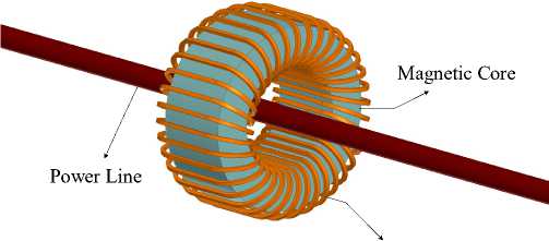
Windings
F i g. 2. Toroidal core for electromagnetic energy harvester structure
Toroidal cores have dimensional variables, such as inner diameter, outer diameter, and height, as seen in Figure 3. These variables are of vital importance in terms of the energy obtained by the harvester. Indeed, the amount of harvested energy varies depending on these geometric variables.
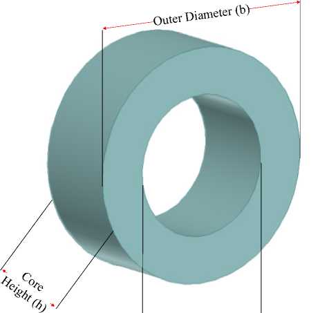
Inner Diameter (a>
F i g. 3. Toroidal core parameters
Magnetic field energy harvesters operate based on the principles of Faraday's law, Lenz's law, and Ampere's law. Magnetic field strength, represented as (H), is dependent on the applied current, and as the current value increases, the magnetic field strength also increases. For a toroidal core, the magnetic field strength is expressed by Equation 1.
h = — 2 к г
.
Magnetic field strength and magnetic permeability determine magnetic flux density in a core. As a matter of fact, the magnetic flux density is obtained by multiplying magnetic permeability and magnetic field strength. The magnetic permeability is the product of the magnetic permeability of air and the magnetic permeability of a material. The magnetic flux density at any radius r in the toroid core is expressed as in Equation 2.
- icos ( wt )
B = > ,
2кг ф21 = J 51 ds 2.
The total magnetic flux in the toroid core is expressed as the area integral of magnetic flux density and shown in Equation 3.
* 21 = y icosM in ( b/ ) h . 2 л v a
The common inductance of the core is obtained by multiplying the derivative of the total flux with respect to the current and the number of turns, as is seen from Equation 4.
L21 = L12 = M = N^d^21, 21 12 2 di
^- hNdn^b/ 1 2 k ^ a
According to Faraday's law, the voltage induced in a toroid is obtained by multiplying the time derivative of the magnetic flux in the core and the number of turns on the core.
V =_ n d ^ 21 ( t ) 22dt ,
V 2 = N 2 ^ ifsin ( wt ) In ( ba ) h.
Thus, the induced voltage of the harvester can be calculated by Equation 5. The highest induced voltage is shown as in Equation 6.
V 2 = N 2 p if In ( ba ) h .
The number of turns in the voltage winding induced through the toroidal core depends on variables, such as magnetic permeability, frequency, line current, and core size. The induced voltage can be obtained along with a mutual inductance, as shown in Equation 7
V2 = Mifsin ( wt ) 2. K .
As clearly seen in Equation 7, the voltage induced by the harvester is directly influenced by the mutual inductance value. This emphasizes the significance of mutual inductance in determining the induced voltage. Furthermore, as previously mentioned and observed in Equations 5 and 6, dimensional variables of the core have a significant impact on the harvested energy through the induced voltage. Indeed, the induced voltage increases with a decrease in the inner diameter of the core and an increase in the outer diameter and height.
The analyses of designed harvesters were performed using the Finite Element Method (FEM). The FEM is used to solve problems by partial differential equations and involve the changes in a specific region. The FEM is extensively utilized in various engineering fields, such as electrical-electronic, mechanical, civil, and biomedical engineering to solve problems with the assistance of computers. With the help of FEM, the region to be solved is divided into a finite number of small regions called meshes. By mathematically modeling and solving the effects of these individual meshes, an approximate solution can be obtained. The accuracy of the solution increases as the number of meshes increases. This method allows for the mathematical modeling and simulation of complex structures, enabling the analysis of complex and time-consuming problems to be solved with a high accuracy in a short time [20].
Results
Toroidal-shaped cores were designed and analyzed with different magnetic materials. The dimensions of the cores were selected as mm in terms of outer diameter, inner diameter, and height, respectively, as 50x30x20 and 60x30x20. The magnetic materials used for the cores were nanocrystalline, ferrite, and silicon steel. The designed cores were examined in terms of mutual inductance, self-inductance, and induced voltage. Table 1 presents the analytically calculated inductance values.
T a b l e 1
Common and Self Inductance of the Cores by Analytic Calculations
|
1 |
Core Size Parameters (mm) |
60x30x20 |
50x30x20 |
|
|
у У g |
Nanocrystalline |
L22 (mH) M (mH) |
34.322600 0.343226 |
24.960000 0.249600 |
|
Ferrite |
L22(mH) |
58.224363 |
42.909350 |
|
|
M (mH) |
0.5822436 |
0.4290935 |
||
|
Silicon Steel |
L22(mH) |
165.0920000 |
121.6670000 |
|
|
M (mH) |
1.6509200 |
1.2166710 |
||
Table 2 shows the inductance values obtained as a result of FEM analysis. The highest mutual inductance value is 1.637694 mH, and the self-inductance value is 164.4343 mH, achieved with the silicon steel material and a core size of 60x30x20. It can be observed that the analytical and FEM results are very close to each other.
T a b l e 2
Common and Self Inductance of the Cores by FEM Analysis
|
Core Size Parameters (mm) |
60x30x20 |
50x30x20 |
||
|
Nanocrystalline |
L22 (mH) |
34.513650 |
25.4815100 |
|
|
У s |
M (mH) |
0.339824 |
0.2501500 |
|
|
Ferrite |
L22(mH) M (mH) |
58.946370 0.582920 |
43.442280 0.429540 |
|
|
Silicon Steel |
L22(mH) |
164.434300 |
110.391100 |
|
|
M (mH) |
1.637694 |
1.098376 |
||
The toroidal harvesters and experimental setup used in the study can be seen in Figure 4. The number of turns in the toroid was determined based on the winding values in Table 4. A 0.35 mm2 copper conductor was selected as the conductor. To increase the line current to the desired value, a transformer with a conversion ratio of 220V:24/12V, 50 Hz, and a 1.5 kVA was used, and a 10 Ohm, 5 A rheostat was used as a pre-resistor to adjust the line current precisely. A clamp ammeter was used to monitor the line current, and multimeters and an oscilloscope were used to measure the induced voltage and the current drawn by the load.
In the experiment, each core was tested within the range of 0‒30 A line current with a precision of 5 A, and the induced voltage values were measured. Then, based on the core that induced the highest voltage, power measurements were performed using this core for harvesting. Different resistance values were used as the load to capture the maximum power during these measurements .

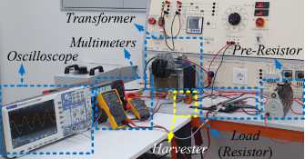
Transformer
Multimeters
Oscilloscope
^^ j i№ й- • •
Pre-Resistor
Load
( Resistor )
F i g. 4. Experiment setup and harvester cores
In this section, the measured induced voltage and harvested power through the harvesters were provided. To test the designed cores, the inductance value of each core was measured using an LRC meter, and the AL and inductance values were calculated. Based on the calculated AL values, the number of turns for the cores was determined. The experiments were conducted using the calculated number of turns as a reference. Table 3 shows the calculated AL values and the number of turns for the harvesters.
AL values and turns of the cores
T a b l e 3
|
Core Size Parameters |
60x30x20 |
50x30x20 |
||
|
Nanocrystalline |
AL |
6348 |
23441 |
|
|
§2 8^ |
Turn |
280 |
146 |
|
|
Ferrit |
AL Turn |
8364.5 244 |
6103.17 286 |
|
|
Silicon Steel |
AL |
47091 |
32375 |
|
|
Turn |
103 |
124 |
||
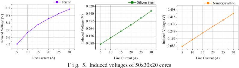
Figure 5 shows the induced voltage variations in the 50x30x20 mm core according to the line current. The line current was increased in steps of 5 Amperes within the range of 0‒30 Amperes, and based on the measurements taken, the highest induced voltage values were obtained by the ferrite core under each current condition.
Similarly, the graphs in Figure 6 show the voltage variations induced by 60x30x20 mm cores according to the line current.
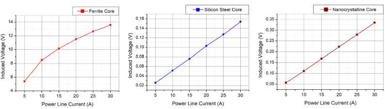
F i g. 6. Induced voltages of 60x30x20 cores
The highest voltage in both dimensions was obtained in the ferrite cores at the determined currents. In the 50x30x20 mm ferrite core, a voltage of 6.61 V was induced at a line current of 10 A, 9.24 V at 20 A, and 11.03 V at 30 A. In the 60x30x20 mm ferrite core, a voltage of 8.51 V was induced at a line current of 10 A, 11.52 V at 20 A, and 13.59 V at 30 A.
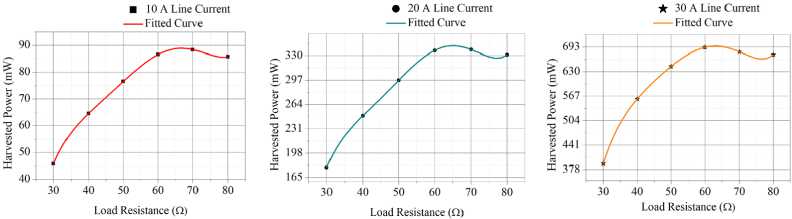
In this section of the study, the power values obtained by the harvester were measured. A 60x30x20 mm ferrite core was taken as the basis for power values, where the highest voltage was induced. The power values were determined by changing the load resistance and measuring the power values, and then converted into a graph using curve fitting method. In Figure 7, power variation graphs are observed depending on the load resistance for line current values of 10, 20, and 30 A.
At a line current value of 10 A, the maximum power harvested was 88.943 mW at a load resistance of 66.869 Ω. At 20 A, the maximum power harvested was 343.561 mW at a load resistance of 64.8485 W. Finally, at a line current of 30 A, the maximum power obtained was 695.516 mW at a load resistance of 62.828 W.
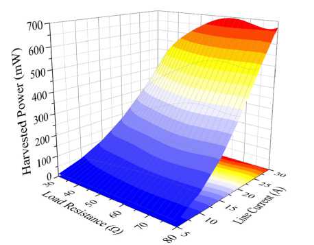
The graph of line current, load resistance, and harvested energy for the 60x30x20 mm ferrite core is shown in Figure 8. The graph was optimized through curve fitting for values with a sensitivity of 5 A within the range of 0‒30 Amperes. At a line current value of 10 A, the power value increased up to 88.943 mW until 66.869 W, and then started to decrease. When the line current was 20 A, the harvested power increased up to 64.8485 W, reached its maximum, and then started to decrease. The maximum power obtained was 695.516 mW at a line current of 30 A. At 30 A, the harvested power increased up to 62.828 W and then, as seen in the graph, started to decrease.

F i g. 7. Harvested power of the core according to load resistance
F i g. 8. Harvested power, line current and load resistance
Discussion and Conclusion
In this study, the design of toroidal-shaped magnetic energy harvesters was carried out to harvest energy from power transmission lines. The harvesters were designed in two different sizes, 60x30x20 mm and 50x30x20mm, with three different materials: Ferrite, Nanocrystalline, and Silicon Steel. The theoretical and FEM analyses of the harvesters were performed with a sensitivity of 5 A within the range of 0‒30 A. These analyses determined the common-inductance and self-inductance values of the harvesters. At the experimental stage, the AL value of each core was measured using an LCR meter, and the winding turns were determined based on these values. The induced voltages of each core were measured using the experimental setup. Detailed experiments were conducted based on the 60x30x20 mm ferrite core, which exhibited the highest induced voltage. Different load resistances were used to find the resistance value for the highest power at each current value. The optimal load resistance for maximum power transfer was determined for each core using the curve fitting method at all current values. According to the results of the study, among the selected materials and under the specified line conditions of 0‒30 A current and 50 Hz frequency, the highest power of 695.516 mW was harvested by the 60x30x20 mm ferrite core harvester at a line current of 30 A. It is believed that this harvested power would be sufficient for the operation of various low-power sensors. Additionally, it is possible to provide energy to batteries using this power.
Submitted 10.07.2023; revised 21.08.2023; accepted 28.08.2023
References Power analysis of toroidal core electromagnetic energy harvesters for transmission lines
- Moser M.J., Bretterklieber T., Zangl H., Brasseur G. Strong and Weak Electric Field Interfering: Capacitive Icing Detection and Capacitive Energy Harvesting on a 220-kV high-voltage overhead power Line. IEEE Transactions on Industrial Electronics. 2011;58(7):2597-2604. https://doi.org/10.1109/ TIE.2010.2098362
- Liu Y., Xie X., Hu Y., Qian Y., Sheng G., Jiang X., et al. A Novel High-density power Energy Harvesting Methodology for Transmission Line online Monitoring Devices. Review of Scientific Instruments. 2016;87(7):075119. https://doi.org/10.1063/L4959556
- Zhuang Y., Xu C., Yuan S., He C., Chen A., Lee W.W., et al. An Improved Energy Harvesting System on Power Transmission Lines. In: 2017 IEEE Wireless Power Transfer Conference (WPTC). 2017. p. 1-3. https://doi.org/10.1109/WPT.2017.7953847
- dos Santos M.P., Vieira D.A., Rodriguez Y.P., de Souza C.P., de Moraes T.O., Freire R.C. Energy Harvesting Using Magnetic Induction Considering Different Core Materials. IEEE International Instrumentation and Measurement Technology Conference (I2MTC). 2014;942-944. https://doi. org/10.1109/I2MTC.2014.6860881
- De Moraes T.O., Malina Y.P., Melo E.C.D.S., De Souza C.P., Experimental Results on Magnetic Cores for Magnetic Induction-Based energy Harvesting. 17th TC-4 Workshop IWADC on ADC and DAC Modeling and Testing. 2013;65. Available at: https://www.researchgate.net/publication/290829983_Ex-perimental_results_on_magnetic_cores_for_magnetic_induction-based_energy_harvesting (accessed 10.06.2023).
- Tashiro K., Wakiwaka H., Inoue S.I., Uchiyama Y. Energy Harvesting of Magnetic PowerLine Noise. IEEE Transactions on Magnetics. 2011;47(10):4441-4444. https://doi.org/10.1109/ TMAG.2011.2158190
- Simic M., Bil C., Vojisavljevic V. Investigation in Wireless Power Transmission for UAV Charging. Procedia Computer Science. 2015;60:1846-1855. https://doi.org/10.1016/j.procs.2015.08.295
- Dalcali A., Balci M.§., Sakar, S. Electromagnetic Energy Harvester Design for Power Transmission Line. Transdisciplinary Journal of Engineering & Science. 2022;14:111-123. https://doi. org/10.22545/2022/00211
- Quyen T., Nguyen C., Le A., Nguyen M. Optimizing Hybrid Energy Harvesting Mechanisms for UAVs. EAI Endorsed Transactions on Energy Web. 2020;7(30). https://doi.org/10.4108/eai.13-7-2018.164629
- Najafi S.A.A., Ali A.A., Sozer Y., De Abreu-Garcia A. Energy Harvesting from Overhead Transmission Line Magnetic fields. In: IEEE Energy Conversion Congress and Exposition. 2018. p. 7075-7082. https://doi.org/10.1109/ECCE.2018.8558356
- Camboin M.M., Baiocchi O., Villarim A.W.R., Catunda S.Y.C., de Souza C.P., Moreira C.D.S. An Automatic Emulation System for Environmental Thermal Energy Harvesting. In: IEEE International Instrumentation and Measurement Technology Conference. 2019. p. 1-6. https://doi.org/10.1109/ I2MTC .2019.8827004
- Nadaf N., Preethi A. Review on Waste Heat Energy Harvesting using TEG: Applications and Enhancements. 8th International Conference on Smart Computing and Communications. 2021. p. 334-339. https://doi.org/10.1109/ICSCC51209.2021.9528196
- Yang Y., Zhu G., Zhang H., Chen J., Zhong X., Lin Z. H., et al. Triboelectric Nanogenerator for Harvesting Wind Energy and as Self-Powered Wind Vector Sensor System. ACS Nano. 2013;7(10):9461-9468. https://doi.org/10.1021/nn4043157
- Wu Y., Zhong X., Wang X., Yang Y., Wang Z.L. Hybrid Energy Cell for Simultaneously Harvesting Wind, Solar, and Chemical Energies. Nano Research. 2014;7:1631-1639. https://doi.org/10.1007/s12274-014-0523-y
- Wen Q., He X., Lu Z., Streiter R., Otto, T. A Comprehensive Review of Miniatured Wind Energy Harvesters. Nano Materials Science. 2021;3(2):170-185. https://doi.org/10.1016/). nanoms.2021.04.001
- Uddin M.N., Islam M.S., Sampe J., Sawal H., Bhuyan M.S. Design and Simulation of Piezoelectric Cantilever Beam Based on Mechanical Vibration for Energy Harvesting Application. In: International Conference on innovations in Science, Engineering and Technology. 2016. p. 1-4. https://doi.org/10.1109/ ICISET.2016.7856532
- Jayarathne W.M., Nimansala W.A.T., Adikary S.U. Development of a Vibration Energy Harvesting Device Using Piezoelectric Sensors. In: Moratuwa Engineering Research Conference. 2018. p. 197-202. https://doi.org/10.1109/MERCon.2018.8421913
- Rodriguez J.C., Holmes D.G., McGrath B.P., Wilkinson R.H. Maximum Energy Harvesting from Medium Voltage Electric-Field Energy Using Power Line Insulators. In: Australasian Universities Power Engineering Conference. 2014. p. 1-6. https://doi.org/10.1109/AUPEC.2014.6966633
- Moghe R., Yang Y., Lambert F., Divan D. A Scoping Study of Electric and Magnetic Field Energy Harvesting for Wireless Sensor Networks in Power System Applications. IEEE Energy Conversion Congress and Exposition. 2009. p. 3550-3557. https://doi.org/10.1109/ECCE.2009.5316052
- Dalcali A. Influence of Rotor Magnet Material and Stator Winding Geometry on Output Torque in Spherical Actuator. Journal of Engineering Sciences and Design. 2019;7(1):145-151. https://doi. org/10.21923/jesd.437980
