Power quality improvement in off-grid renewable energy systems

Author: Temerbaev Sergey A., Dovgun Valery P., Shevchenko Elena S.
Journal: Журнал Сибирского федерального университета. Серия: Техника и технологии @technologies-sfu
Article in issue: 7 т.7, 2014.
Free access
In this paper a grid-interfacing converter system with voltage and current harmonics compensation capability is considered. The idea is to integrate the power generating functions of the converter with the power filter harmonic mitigation capabilities. The analysis of compensation characteristics of different hybrid power fi lter configurations is carried out. The control method based on adaptive digital system processing is proposed. The current detecting scheme independently controls fundamental current and harmonic distribution system currents. Computation of the harmonic compensation current is performed by the adaptive notch infinite impulse response (IIR) digital fi lter. The fi lter`s parameters are made adaptive with respect to the grid frequency fl uctuations. MATLAB/SIMULINK power system toolbox is used to simulate the proposed system. The presented simulation results confirm the effectiveness of the proposed method.
Renewable energy system, harmonics, hybrid power fi lter, power quality
Short address: https://sciup.org/146114902
IDR: 146114902 | UDC: 621.311
Улучшение качества электроэнергии в автономных системах электроснабжения, использующих возобновляемые источники энергии
В статье рассмотрены конверторы, обладающие способностью компенсировать высшие гармоники токов и напряжений в автономных системах электроснабжения. Идея заключается в объединении функций конвертора и силового фильтра гармоник в одном устройстве. Проведен анализ основных конфигураций гибридных фильтрокомпенсирующих устройств. Предложен метод управления характеристиками фильтра, основанный на использовании алгоритмов адаптивной цифровой обработки сигналов. Схема выделения составляющих тока обеспечивает независимый контроль гармоники основной частоты и высших гармоник. Вычисление компенсирующего сигнала осуществляется с помощью цифрового режекторного фильтра с бесконечной импульсной характеристикой. Для моделирования предложенной системы использована среда MATLAB/SIMULINK power system toolbox. Результаты моделирования подтверждают эффективность предложенного подхода.
Text of the scientific article Power quality improvement in off-grid renewable energy systems
Calculation of compensating signals is the important part of AHF control and affects their transient as well as steady-state performance. Different control methods have been proposed, ranging from the use of fast Fourier transform (FFT) to the instantaneous P-Q theory, artificial neural networks and adaptive notch filters.
The current harmonic compensating approach, considered in [3, 4], uses an adaptive line enhancer (ALE) based on finite impulse response (FIR) digital filter. The serious limitation of ALE is a relatively slow rate of convergence. Application an infinite impulse response (IIR) notch filter is attractive since it requires much smaller filter length and provides better convergence properties compared to the ALE with FIR filter.
This article focuses on power quality improvement in the off-grid renewable energy systems with the help of hybrid power filters (HPF). Active part of HPF may be integrated with the power electronic converter. Compensating characteristics of different HPF configurations, suitable for integration with renewable energy units, are considered. The load harmonic compensation is performed through using the adaptive two-band infinite impulse response (IIR) filter. Simulation results confirm the effectiveness of the proposed method.
Renewable Energy System Configuration
Renewable energy sources are interfaced with the grid through power converters. Depending on their operation in off-grid system, power converters may have the following modes of operation: voltage-source, current-source, and active power filter mode [2, 6]. In voltage-source mode converter can operate in off-grid system as a grid-forming unit. In this mode of operation the ac voltage and frequency are controlled to meet the power quality requirements.
According to [1, 2] most of the power converters in RES systems operate in current- source mode. PV inverters and wind power systems are typically renewable generation units, operating in currentsource mode with dc to ac energy conversion. In this mode control of RG unit is performed by injecting of current with the same frequency and phase of grid voltage. Amplitude of current depends on the power available from a renewable source.
In active power filter mode AC current or voltage harmonics are generated to mitigate waveform distortions.
Hybrid Power Filter Analysis
There are two main categories of APF exist: shunt filters and series filters. The shunt APF should operate as a current source and inject the compensation current into power system to cancel the harmonic current, produced by current type nonlinear load [5]. The series active filter operates as a voltage source and generates a voltage proportional to the source current harmonics. The series APF can effectively suppress harmonics generated by voltage-type nonlinear loads.
In this section the following topologies of hybrid power filters are considered:
-
1. HPF with shunt passive filter and shunt active power controlled by the PCC harmonic voltage V CPh .
-
2. HPF with passive filter and active filter connected in series and controlled by the grid harmonic current I Gh .
-
3. Combined HPF with shunt passive filter and series active filter controlled by the grid harmonic current I Gh .
-
A. Shunt hybrid power filter controlled by the harmonic voltage VCPh.
This topology is shown in Fig. 1. It is suited with the DPG unit connected in parallel to the grid.
The grid is presented by a sinusoidal voltage generator in series with grid impedance Z G = R G + j ω L G . The nonlinear load is presented as harmonic current source. I Lh is the harmonic of distorted load current, and IGh is the harmonic of the grid current. The passive filter has two branches tuned to 5-th and 7-th harmonics. The shunt AF is assumed to be an ideal current source that injects a compensating current, proportional to the harmonic components of the coupling point voltage VCPh : I AF = G af ∙ V CPh .
With reference to Fig. 1, the grid current and PCC voltage can be deduced as a function of the load current I Lh :
Yg
I Gh — I Lh ; V CPh
Yg + Ypf + Gaf
Y g + Y f + G f
ILh .
According to (1) active power filter attenuates propagation of voltage and current harmonics generated by the nonlinear load.
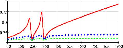
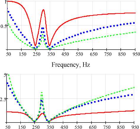
Fig. 2 shows a set of curves representing a frequency characteristics of distributing factor I Gh / I Lh and trans-resistance V Gh / V Lh .
Equations (1) yield the following:
V . ■ 0, I gh ” 0 if G af >> fc + Y pf |-
The line current and CP voltage are almost sinusoidal if (2) is satisfied for each harmonic of order h .
-
B. Series hybrid power filter controlled by the grid harmonic current IGh.
This configuration is shown in Fig. 3. The AF is equivalent to controlled voltage source: A AFh = R af ∙ I Gh .
The grid current and PCC voltage
I - Z pf I V - Z g Z pf I Gh Lh ; CPh Lh .
Z pf + Z g + R af Z pf + Z g + R af
The AF is controlled in such a way to act as a resistor in series with grid impedance. Frequency characteristics of distributing factor I Gh / I Lh and trans-resistance V Gh / V Lh are presented in Fig. 2.
The larger R af is chosen, the lower the harmonic current I Gh and V CPh will be. In this structure the rating of APF is very small. It is preferred for power filter mode.
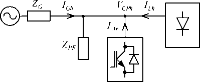
Fig. 1. Topology of shunt HPF
1.5
50 150 250 350 450 550 650 750 850 950
Frequency, Hz
Frequency, Hz
G af = 1; G af = 5; G af = 10
Fig. 2. Frequency characteristics of shunt HPF
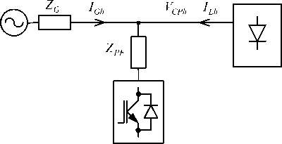
Fig. 3. Topology of series HPF
-
A. Combined hybrid power filter controlled by the load harmonic current IGh.
This configuration is show n in Fig. 5.
Compensating voltage of AF is proportional to the harmonic components of the grid current: VAFh = Ka f ∙ ICh .
The grid current and PCC voltage
I Zf I Z f ( Zg + K af ) I
Gh Z f + Z g + K f Lh ; CPh Z f + Z g + K f Lh .
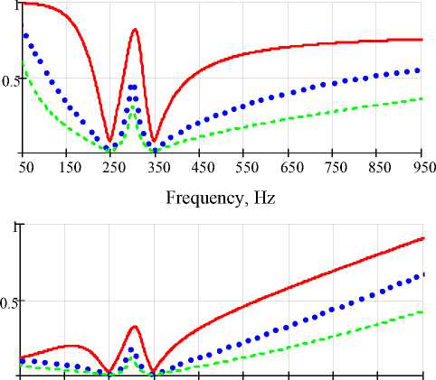
A set of curves representing a frequency characteristics of distributing factor I Gh / I Lh and transresistance VCPh / VLh is shown in Fig. 4.
The combined topology is suited with the RE S units in the voltage-source mode.
50 150 250 350 450 550 650 750 850 950
Frequency, Hz
R af = 1; R af = 5; R af = 10
Fig. 4. Frequency characteristics of series HPF
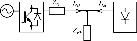
Fig. 5. Topology of combined HPF
Calculation of the Compensating Signal
The control strategies to generate compensating signals are based on the frequency-domain or time-domain techniques [1, 2, 5]. Control strategy in the frequency domain is based on the Fourier analysis of the distorted current or voltage. The high-order harmonic components are separated from distorted signals and combined to form compensating commands. But the discrete Fourier transform (DFT) loses accuracy in nonst ationary situati ons.
Commonly used calculation methods in the time domain are the instantaneous active and reactive (P-Q) theory approach, neural network theory, notch filter approach, adaptive signal processing. Most of these algorithms have a much better dynamic response than the DFT. In this paper computation of the load harmonic compensation current is performed by the adaptive notch IIR filter.
The magnitude characteri stic of the ideal notch filter is defined as:
H(e} го ) =
1 to ^ го 0
1 го = го 0
Frequency, Hz
K af =1; K af =5; K af =10
-
Fig. 6. Frequency characteristics of combined HPF
In (3) ω0 is the notch frequency. Notch filter extracts fundamental sinusoid from distorted current waveform without harmfully phase shifting of the high-order harmonics. The ideal notch filter has zero bandwidth. However, zero bandwidth cannot be realized in practice.
The simplest type of adaptive notch digital filter is the adaptive line enhancer (ALE) proposed by B. Widrow [7]. The adaptation of the finite impulse response (FIR) filter is realized by using the least mean square (LMS) algorithm. Shortcomings of this ALE are relatively low convergence speed and potential instability.
An infinite impulse response (IIR) filter provides a sharper magnitude response than the FIR adaptive line enhancer. Also, it requires much smaller filter length, than the ALE based on FIR filter.
Consider the two-band infinite impulse response (IIR) filter (Fig. 7). It realizes two double-complementary transfer functions:
F 1 ( Z ) = ETZ) = i^ + A ( Z )], X ( Z ) 2
E ( Z )
F 2 (Z ) = = -[1 - A ( Z )],
X ( Z ) 2
where A ( z ) is a second-order all-pass transfer function. F 1( z ) is a notch-type transfer function and F 2 ( z ) is a bandpass-type transfer function. The tuning frequency is equal to ω 0 .
A lattice-form realization of all-pass IIR digital filter is shown in Fig. 8. Input and output signals in Fig. 8 are x ( n ) and y ( n ). Transfer function of the lattice all-pass filter is the following:
Y ( z ) _ z + k 1 (1 + k 2 ) z -1 + k 2
A ( z ) , . 1 1
X ( z ) k 2 z - 2 + k 1 (1 + k 2 ) z -1 + 1
The polynomials of num erator and denominat or of Equation (6) have mirror symmetry. Accordingly, lattice IIR-filter realizes all-pass transfer function with module equal 1 in the all frequency range. Using equation (4), t he transfer function of the notch filter, shown in Fig. 6, is presented as:
F ( z ) = 1 ( z 2 + 2 k , z - + 1X1 + k 2 ) , 2 k 2 z 2 + k 1 (1 + k 2 ) z 1 + 1
where k 1 is the adaptive coefficient which should converge to - cosm0 for reject a sinusoid with frequency ω 0 .
Adaptive IIR filter in Fig. 8 is adapted by using adaptive algorithms related to the lattice FIR filters. The lattice structure of second-order FIR filter is shown in Fig. 9. In this article, gradient lattice algorithm [8] is used for adaptation purposes. It has been chosen because of its low complexity and high-speed convergence. Update of the coefficients k 1 and k 2 by using gradient algorithm is given as follows:
2 Ц
k(n + 1) = k(n)- D——(e ,(n) ги (n — 1)+ e-1(n) r(n)), n where μ is an adaptation step. Parameter Di(n) is defined as:
Di(n) = 3Di(n) + e,2-,(n) + г,2,(n -1), where β is a forgetting factor: 0< β <1.
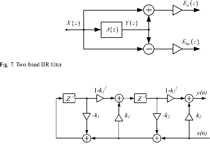
Fig. 8. Lattice structure of second-order all-pass IIR filter
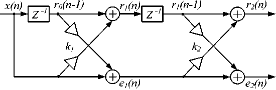
Fig. 9. Lattice structure of second-order FIR filter
Simulation Results
The system was simulated using MathLab/S ink to verify the propo ed algorithm. Fig. 10 shows the model and parameters a presented in Table I.
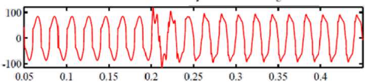
Schematic diagram of proposed controlled shunt HPF is shown in Fig. 7. The linear load is defined as resistance R, non-linear load inc udes a rectifier with RL lo on the dc side. Passive filter includes two LC circuits, tuned to 5th and 7th harmonics. Simulation process is divided into steps: connection of PF and connection of AF.
The grid supplies a non-linear current load, the THD1 of grid current is 21,4 %. At the first simulation step the passive filter is connected in 0,2s and a waveform of grid current is more sinusoidal ( THD1 =18,8 %). Simulation results are performed in Fig. 11.
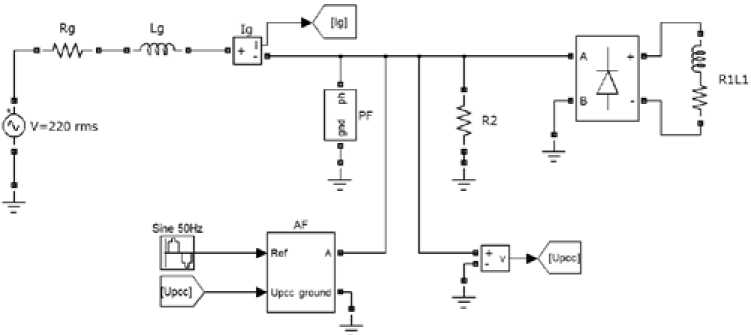
Fig. 10. MATHLAB scheme of shunt HPF system
Table 1. Parameters of the Model
|
Grid |
Load |
Passive filter |
|
AC=220 V |
R1=3.7 Ω |
C5=263.9 µF |
|
f=50 Hz |
L1=10 mH |
L5=1.57 mH |
|
Rg=0,1 Ω |
R2=15 Ω |
C7=143.25 µF |
|
Lg=0,2 mH |
L7=1.47 mH |
Time
Fig. 11. Grid current on the first simulation step.
Time
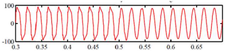
Fig. 12. Grid current on the second simulation step
The second step is APF connection in 0,5 s (Fig. 12). The resulting THD 1 of grid current is equal to 3,12 %.
Conclusion
In this paper a grid-interfacing converter system with voltage and current harmonic compensation capability is considered. Compensating characteristics of different hybrid power filter topologies are considered. A novel adaptive method for grid current harmonic compensation is proposed. The load harmonic compensation is performed by using the lattice-form adaptive notch IIR filter. It is shown that adaptive notch filter can be successfully employed in active harmonic filter for the sake of harmonic mitigation. The proposed approach does not need any training of the notch filter. The performance of the proposed control system is verified by computer simulation in MATLAB/SIMULINK. The simulation results are presented showing the effectiveness of the proposed method.
