Powers adjusting wind turbine means investigation

Author: Udalov Sergey N., Zubova Natalya V., Achitaev Аndrey А.
Journal: Журнал Сибирского федерального университета. Серия: Техника и технологии @technologies-sfu
Article in issue: 5 т.10, 2017.
Free access
Today, wind power is the fastest-growing renewable energy source. Wind power is free, clean and endless. Furthermore, the cost of the electricity produced by wind turbines already reached the point where it is comparable with that of electricity produced by some of the conventional, fossil based power plants. However, it is still important to improve upon the technology in order to keep wind energy economically competitive with traditional and other renewable energy sources. In this paper, the idea of a variable-length blades, microdevices, and plasma jet drives are offered as a means of improving energy generation wind turbines.
Wind turbine, microflaps, variable length blade, flow control
Short address: https://sciup.org/146115234
IDR: 146115234 | UDC: 621.311.24 | DOI: 10.17516/1999-494X-2017-10-5-664-681
Исследование средств повышения регулирования мощности ветровой турбины
Сегодня энергия ветра является самым быстрорастущим источником возобновляемой энергии. Ветровая энергия доступна, экологически чистая и бесконечна. Кроме того, стоимость электроэнергии, производимой ВЭУ, уже достигла точки, где она сравнима со стоимостью электроэнергии, производимой некоторыми электростанциями на основе ископаемых видов топлива. Тем не менее по-прежнему важно улучшать технологии для того, чтобы сохранить энергию ветра экономически конкурентноспособной по отношению к традиционным и другим возобновляемым источниками энергии. В этой статье представлена идея переменной длины лопасти, микроустройств и плазменных приводов, которые предлагаются в качестве средства улучшения производимой энергии ветровых турбин.
Text of the scientific article Powers adjusting wind turbine means investigation
а)
b)
c)
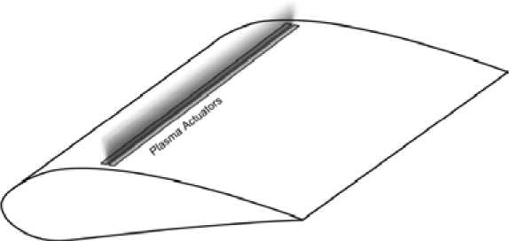
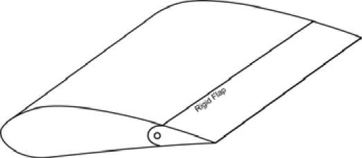
Fig. 1. Aerodynamic lift control devices: a) jet nozzle drive action; b) plasma device; c) flaps device
An analysis of the technology is needed. We have developed a mathematical model of the device,
,
which allows us to analyze the structure of the blade, the placement of these devices and their influence on the lifting force.
Below is a mathematical modeling of aerodynamic interaction of the jet nozzle equipped blade with the wind flow, the actions described by the Navier-Stokes equations [2, 3]:
Р1 - д u\ д t + р1 (u - V) u = V -
- p -1 + n(v u + (V u) T)
+ F V-u = 0,
where u – speed of wind flow, m/s; p – pressure, Pa; η – kinematic viscosity ∙ Pa·s; F – force, N; ρ 1 – flux density, kg/m3; I – the unit outward normal to the surface; t – time, s; and T – matrix transposition index.
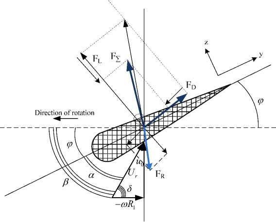
Fig. 2. Vector diagram of forces and air flow rate on airfoil cross section
Calculation of the lift in a reactive gas flow is based on the dynamics of jet propulsion developed by Meshcherskiy. Lift, developed in cooperation with the blade wind flow, velocity u, is represented by the formula (Fig. 2):
MdU = 12^^12P1u 2 CL + ^dm, (2) dt 2 dt where FR = и dm/ dt is reactive force, as it acts on the blade at the expiration air mass m of the injector nozzle, H; и - velocity gas flow from the nozzle, m/s; CL - lift coefficient, dim; U - linear velocity of rotation of the blade m/s; M – blade mass, kg; and R – radius of the blade, m.
Modeling of processes occurring in the turbine was conducted on the basis of the finite element method (FEM) and calculation of flow dynamics using computational fluid dynamic (CFD) (Fig. 3), analyzing the physical processes under the influence of other devices, ultimately effecting the amount of lift. The aerodynamic properties of the blades with active aerodynamic devices are modeled using a special algorithm ARC2D, which is used for analyzing laminar flow [2]. The basis for the software tools used for analysis is ANSYS CFD. Algorithm ARC2D, based on twodimensional Navier-Stokes equations [3], was used to calculate the aerodynamic coefficients of lift and drag. Using CFD allows for consistently identify the changes in wind energy conversion efficiency of the airflow at the selected blade profile and its’ changes due to the impact of active aerodynamic devices [2].
The graph depicted in Fig. 4 shows the dependence of lift on the velocity of the gas in the nozzle. Depending on the wind speed through the jet nozzle drive, lift may be kept constant even at a sufficiently low speed wind. Compressing air, storing it the wind turbine, and utilizing it during times of need is more cost effective than utilizing a separate mechanism (i.e. ballast) to produce and store compressed air.
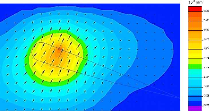
Fig. 3. Simulation results of action of the jet drive on lift
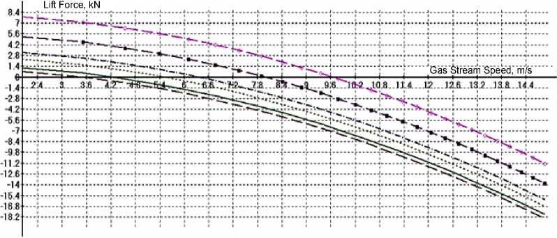
----Wind Speed 10 m/s --Wind Speed 8 m/s .......Wind Speed 13 m/s -----Wind Speed 15 m/s —■ •— Wind Speed 19 m/s «-»*-» Wind Speed 23 m/s
Fig. 4. Results of modeling the influence of the flow rate of the nozzle drive on lift force for different values of wind speed
This device allows operation at the maximum power factor of the wind power plant, as well as the ability to maintain a constant rotation speed for a larger wind speed range.
Plasma Control Device
A known issue with the plasma actuator configurations is their sensitivity towards Reynolds number (Re) variations and more specifically, their reduction in effectiveness with the increase – 668 – of the free-stream velocity [8]. Pechlivanoglou and Eisele [9] investigated the operation of plasma actuators on wind turbine airfoils at a wide range of Reynolds numbers and found that the effect of all the investigated plasma actuators vanished at Re > 105. The energy conversion efficiency is also another operational parameter which highly depends on the actuators design, and undergoes further investigation. Currently plasma actuator systems have low efficiency and very high thermal losses. Additionally the effects of environmental conditions need to be further investigated to examine the possibility of further implementation of plasma actuators on wind turbine blades. More specifically, the plasma actuators would be required to operate effectively and reliably under rain, hail, ice, tolerate dust and contamination, and lightning strikes [6].
Plasma actuators can be used in various types of flow control and flow modification applications depending on their type and positioning. The use of plasma actuators in an intermittent mode allows for the excitation of Tollmien-Schlichting instabilities in laminar flows, and thus triggering transition and achievement of stall delay. Other types of actuators, such as the plasma wall jet actuators, are able to create plasma sheets, vertical or at angle with the wall surface, thus achieving effects similar to vortex generators [7, 8]. Shear flows can also be manipulated by plasma actuators via triggering Kelvin-Helmholz instabilities [10].
The application of these principles in airfoil flow control is currently under extensive investigation. The results for low and medium Reynolds numbers are positive, while the effectiveness of these solutions at high Reynolds numbers is significantly reduced [8]. With respect to wind turbine applications, plasma actuators are under extensive research [9, 11] and their applications in this field seem to be promising. Apart from the apparent application in substitution of the popular passive vortex generator solution, there is also the possibility to utilize them as means of drag and vorticity reduction at the blade root region. Recent experiments by Pechlivanoglou and Eisele have shown that the existence of plasma actuators could reduce the drag due to the Karman vortex shedding behind a bluff body and at the same time generate lift. Such a bluff body is the cylindric root of wind turbines blades where the application of plasma actuators is currently investigated.
The DC surface corona discharge actuator consists of two wire electrodes mounted flush on the surface of a dielectric profile (Fig. 5 a ). When a high DC voltage (>10 kV) is applied, a corona is formed around the smaller diameter wire (usually the anode) and an electric wind is created tangential to the surface between the two electrodes. The electric wind is capable of modifying the boundary-layer airflow profile. Figure 5 b displays a visualization of low velocity airflow along a flat plate. If the actuator is off, the smoke remains horizontal. When the actuator is active, flow above the anode is entrained towards the surface from the outer layer, causing the smoke to be drawn to the surface and then accelerated in the discharge region. The advantage of this device is that it requires a simple power supply; however, the design is limited to use in an electric wind velocity of only a few m/s [12].
Electric field strength produced by a flat plate is determined by the following equation [13]:
r
r
r j j
E = + -j- .
2 • ^ 0 2 • -
where ja is surface density of an anode charge; jk is surface density of a cathode charge, C/m2; ε0 is dielectric constant, 8.85•10-12 F/m; E is electric field strength, V/m.
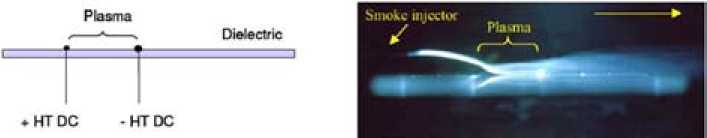
a) b)
Fig. 5. a) Schematic view of drive DC corona discharge, b) 2D visualization of controlled air flow along the flat plate [14]
The Finite Element Method (FEM) method in QuickField was used to analyze the electrostatic field [14]. Electrostatic problems are described by the Poisson equation for the scalar electric potential U. The equation is as follows [14]:
Pv (q) = -
dx
5 U
5
^x - Г^г1 £y . dx ) dy (
dU ) cy ),
where U is voltage applied to a plasma actuator, V; εx, εy are components of the dielectric tensor; ρV is volume density of an electric charge.
Electric field strength is given by the following expression:
E = -V U.
The electric charge of an ozone particle in the electrostatic field is given by:
q = 4Л8й гФо, where q is electric charge of an ozone ion, C; r is distance from the particle to the considered point of the space, m; φ0 is electric potential, V.
In the plasma, an ozone particle is surrounded by other charged particles. Owing to Coulomb (electrostatic) attraction, plasma particles prevail nearby the considered particle which have an opposite charges related to the charge q . They weaken (or screen) the particle field in the plasma. As is known, a potential φ of a charge q field is decreasing with the distance r in the plasma faster than in a vacuum.
4П£ о r^
- г/
eD
A Debye screening length D is determined by [16]:
D = ^*?. (8)
where T2 is absolute temperature of electrons and ions in the plasma, K; k is Boltzmann constant, 1.3807•10-23 J/K; n 0 is charge particle concentration, m-3; e is charge of the electron, C.
Equation (6) allows for the utilization of the calculation of lift force under plasma actuator operations, and its influence on components under examination.
Fig. 6 shows a cross section of the airfoil. When airfoil flows act as an aerodynamic force, they
,
can be divided into two components: the lifting force and resistance. The lifting force acts on the airfoil
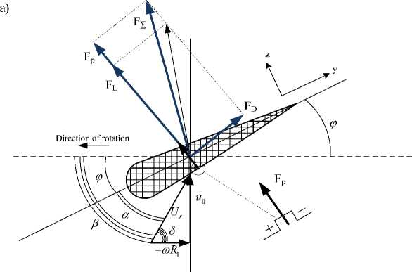
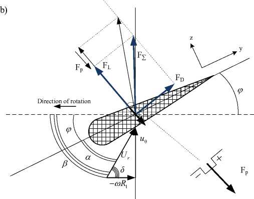
Fig. 6. Vector diagram of forces and air flow rate on airfoil cross section: a) with increasing lift force; b) with limited lift force
perpendicular to the direction of flow leakage rate ( υr ). The resistance force coincides with the direction of the velocity vector free stream flow. Figure 6 depicts the lift ( dF L ) and drag ( dF D ) forces are denoted respectively, as well as the plasma actuator action according to its location on the blade surface. The angle between the direction of flow and speed free stream is α.
Lift ( dFL ) and drag ( dFD ) forces are determined by [16]:
dF L ( x ) = у c h ( x ) ■ U r ( R ) 2 ■ C L ■ d x , dF D ( x ) = P 2v ch ( x ) ■ U r ( R 1 ) 2 ■ C D . dx ,
where ρ1 is air density, 1.223 kg/m3; Ur is relative wind velocity, m/s; CD is drag force coefficient; C L islift force coefficient; F D is drag force, N; F L is lift force, N.
The resultant relative velocity defined through its direction δ and its modulus Ur , which is determined by the rotational speed ω through:
I U I o = arctan I —— I ,
( to R i )
22 u 0 2
Ur — ® I —+R R1 I, I ® J where u0 is wind speed, m/s; ω is angular speed, rad/s; R1 is blade radius, m.
Calculating the component p makes it possible to determine the amount of lift. The wind speed given by the boundary condition is constant. For calculations of mechanical tension, wind speed is formulated numerically through pressure, described as [5, 16]:
p = CL P uL ±A p , 2
where p is air pressure, Pa.
The pressure difference caused by gas ionization depends on temperature and electric field strength.
A p = f - -1 1 J P (T ) RdT = f - -1 1 P o • J " e" qEkT RdT , I P i P l J T I P > P l ) T ,
where μ 1 is ozone molar mass, 48•10-3 kg/mol; μ 2 is oxygen molar mass, 32•10-3 kg/mol; T 1 isabsolute temperature of ram air, K; T 2 is absolute temperature of electrons and ions in the plasma, K; R is universal gas constant, 8.3145, J/(mol•K).
The pressure difference may be also given by:
A p =
P l U^
where ρ2 is ozon density, 2.14 kg/m3;
Consider (10) and derive the equation for u 1 :
- f - -1 p0 • J eqEkTRdT. p11 p1 Pl J
An additional load acting on a wind turbine blade is expressed by:
Fp = ^2 [- - -1 Po • Ao • ClT eqEkTRdT,(15)
Pi I Pi P2)
where F p is force of influence of a plasma flow on a blade, N; A 0 is plasma actuator area, m2.
According to the Wiedemann–Franz–Lorenz law, which makes a relation between the thermal conductivity, the electrical conductivity and the temperature for molecules of an ionized ozone, the following expression is obtained [18]:
T _ 5 X q г
2 OTt2 k2, where о is electric conductance of an ionized gas, Ohm-1; X isthermal conductivity of ozone molecules, W/(m•K).
Using the similarity method for problems of aerodynamics and mechanical strength, mechanical field calculations are carried out, where pressure increment produced by ionized area of a wind turbine blade is taken as initial data [19].
The software package QuickField was used again, this time to model the influence of the DC surface corona discharge on wind turbine blades [20].
Figure 7 depicts the calculation results of the electrostatic field, on which a visible area of a high concentration of lines of force on the surface is causing a corona discharge. Ionized gas creates extra pressure, and in turn, affects the lifting force.
Figure 8 shows the calculations of mechanical deformations performed by usage QuickField. This software allows solving problems of the theory of elasticity in the terms of plane stresses, plane
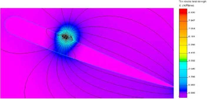
Fig. 7. The result of the calculation of the distribution of the electric field on the surface of the blade under the influence of the DC surface corona discharge mechanical stresses
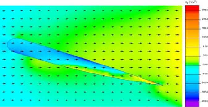
Fig. 8. The result of the calculation of the mechanical stress distribution deformations and axially symmetrical stress distribution with isotropic and orthotropic materials. In two-dimensional formulation, the displacement field is assumed to be completely defined by the two components of the displacement vector δ at each point [20]:
{ # 1 =
5x I 5y
where δx, δy are components of the tensor of mechanical displacements, mm.
The corresponding stress is defined as:
^
И = 1 °y
>
Txy where σx, σy, τxy are components of the tensor of mechanical deformations, N/m2. The equation for volume force density is given by:
-.
- fx
- fy
ax ay
"
S t S ct
^ + _y
9x 9y where ƒx, ƒy are components of the volume force vector, N/m3.
Calculations of the fy component enables for determination of the lift force.
Wind speed, being the constant value, is given by a boundary condition. In the terms of stresses, wind speed is formed through the pressure parameter according to the following equation:
p = p i u 0
p 0 2
.
Calculations of the mechanical deformations were conducted in QuickField. Figure 8 shows the representation of the flux field calculation result of mechanical deformations that affect the wind turbine blade in contact with wind flow.
Figure 9 shows the calculation results based on the blade lift versus angle of attack, which illustrates the effect of increasing the regulating capacity of the wind turbine blade lifting force using a DC surface corona discharge on its surface.
The significant advantages of the Plasma Actuators in the field of mechanical structure (e.g. small size and robust construction) lead to easy and effortless integration on wind turbine blade structures. The integration process involves a simple adhesion step where the plasma actuators, in the form of stripes, are glued on the blade surface. The only elements that need to be properly integrated are the actuator power cables. The overall power requirement of such systems is very low [14, 15].
The Concept of Variable Length Blades
The variable length turbine blade was first conceptualized in 1997. In 2002 the first variable length wind turbine was put on a Bonus 120 kW turbine [21]. The blade changed in length from 8 meters to 11 meters, using an existing 9 meter blade as a plug. The proof of concept blades flew – 674 –
Lift Force, N
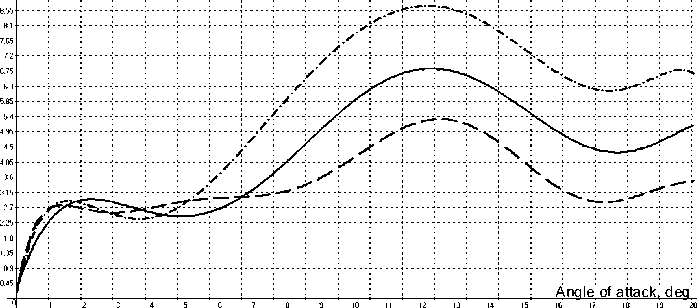
plasma actuator in the lower part of the blade the absence of a plasma actuator plasma actuator at the top part of the blade
Fig. 9. Comparative characteristics of the wind turbine blade lift versus the angle of attack for 34 months.The blades were made out of Kenetech 56-100 tips mounted to slides on the Aerostar 9 meter blades. Eventuallythe prototype blades were replaced by proof of manufacture (Veriablade) blades made during the project [22].
The mathematical model of this device is described by:
P (x) = CP1P1 u 3nR,(x )2, (21)
where C p is power factor of wind turbine.
The basic concept of variable length blades is to increase the swept area of the rotor when there are low winds. As winds increase, the rating of the turbine will be achieved, and as the wind continues to increase, the blades are retracted. This retraction of blades reduces the swept area , of the rotor, which lowers loads on the turbine, and maintains a pre-determined turbine power output. In stormy conditions, the blades can be run shorter than the standard length blades they replace.
Calculations have shown that power is increased by 30% by changing the length of the blade and these blades more effective at low wind speeds in Zone 2 (Fig. 10).
Experimentally obtained data confirmed the theoretical assumptions and calculations. Figure 11 shows the power produced by the proof of concept blades in short, medium and long positions [22].
In summary, the advantages of variable length blades are: improves power production in low winds; allows turbines to continue running in higher wind speeds than standard bladed turbines; reduces the need for different size blades for different wind regimes; reduces the number of blade molds a manufacturer must make to support a single size of turbine; allows control of peak power output; reduces array losses; lowers the cost of wind energy by improving annual power output; makes shipping and installation easier by shipping in a shortened position; allows blades to be self cleaning for dirt and ice removal; and limits damage in extreme winds because blades can be shortened to less than standard length.
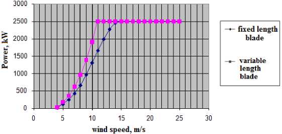
Fig. 10. Comparison of the power curves of turbines with variable length blades and fixed length blades
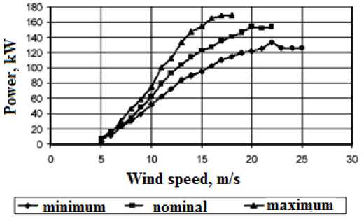
Fig. 11. Experimental power curves for variable length blades
The development of such systems is still at the research stage, but it is likely that in the near future, they will compete with fixed length blades, as they have obvious efficiency improvements.
Active Flow Control Devices
One foreseeable way to counter excessive loads is to supplement current full-span pitch control with active flow control (AFC) devices. Pitching would still be used to optimize energy yield and control aerodynamic torque, while AFC devices would be able to react quickly to reduce the oscillatory and high-frequency loads caused by turbulent winds. The operation of AFC devices also has some potential secondary benefits: devices may be deployed to increase lift of the blade at low wind speeds, allowing the turbine to cut-in earlier and capture additional energy; active devices could aid in energy capture and load mitigation on turbines that experience high array effects; devices could be used to prevent tower strikes, allowing for larger diameter rotors to be used and thereby increasing energy capture; and aerodynamic performance enhancement and noise reduction could be realized by maintaining laminar flow over a larger area of the blade.
There are fifteen devices that have shown potential for wind turbine control and merit future research. However, several of the techniques have not yet been investigated for wind turbine control. Microflaps are the most promising.
The microflap is a rotating device. It takes the position of the trailing edge and is able to rotate 90° in both directions. The optimum microflapheight is on the order of the boundary layer thickness (1-2% chord). A CFD model of a microflap is shown in Fig. 12. Rotating the flap up towards the suction surface reduces lift and rotating it down towards the pressure surface increases lift. This concept is appealing because the trailing-edge location provides more effective lift enhancement and the design does not require a blunt trailing edge. Limited studies have been conducted on this concept, which makes it difficult to define all of the benefits and drawbacks. Some anticipated hurdles are minimizing air leakage and designing a simple, effective actuation system that is capable of rotating the flap bi-directionally to an angle of 90° [23].
Results of Modeling and Calculation Lift Force
This device has been modeled using the software package ElCut and Comsol and the results are given above. Profile S830 was selected for investigation (Fig. 13).
Main assumptions and suggestions: Air movement – laminar; neglect transients in aerodynamics blade; deformation is neglected in calculating the elastic stress; step of discretization for rotation angle ω – 5 degrees.
From modeling results, the characteristics of the distribution of air flow pressure acting on the blade (Fig. 14), the distribution of the velocity field of the wind flow in the boundary layer of air surrounding the blade (Fig. 15), and, as a final result, dependence of the lift force on the angle microflaps to the blade surface were obtained (Fig. 16).
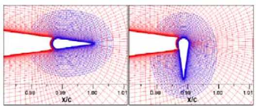
Fig. 12. Model of a microflap in two positions
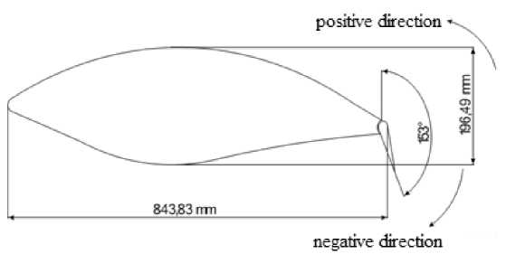
Fig. 13. Profile of the blade S830
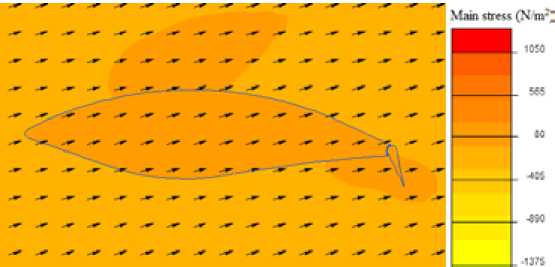
Fig. 14. Pressure distribution of the air flow, acting on the blade
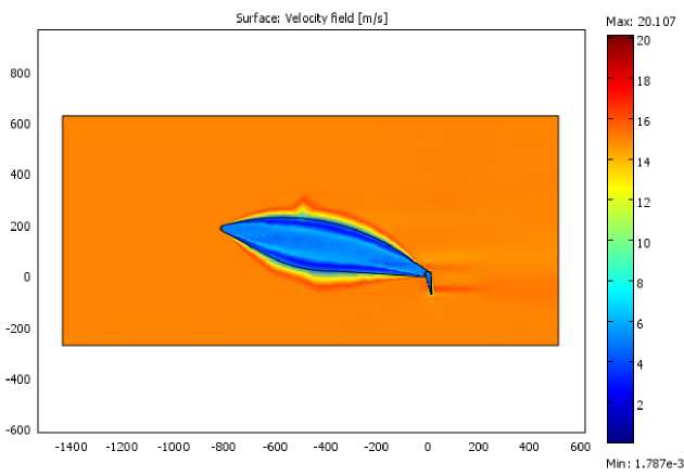
Fig. 15. Distribution of the velocity field of the wind flow in the boundary layer of air, surrounding the blade
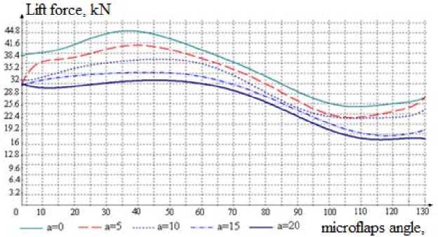
Fig. 16. The lift force for the blade surface
degree
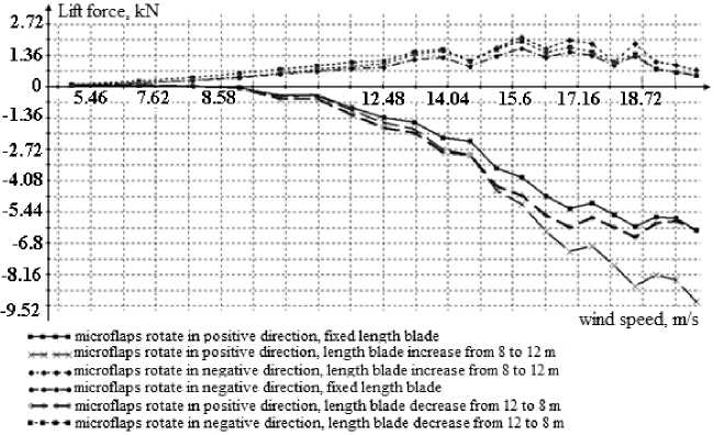
Fig. 17. Lift force change (wind turbine operating with variable blade geometry)
After running simulations of microdevices and variable length bladesseperately, it was decided to combine these two methods and evaluate the benefits of variable geometry. Simulations were also produced using the ElCut. Blade length varies from 8 to 12 meters, wind speed from 5 to 14 m/s (zone 2), the microflaps rotation angle of ± 40 degrees. The simulation results are presented in Fig. 17.
Conclusions
Plasma actuators have received considerable attention over the recent years as a practical flow control device due to their advantages over fluidic and mechanical devices. They are able to directly convert electrical energy into kinetic energy, which is used to modify the airflow. They have advantages over mechanical devices; the device is simple, lightweight and uses no moving parts; therefore, it is likely not be a source of vibration or noise.
Research has also shown that the presence of the electrodes does not interfere with the surrounding airflow when inactive and major modifications to the turbine blade are not required for installation. Another feature is that plasma actuators can be designed to operate in co-flow and counter-flow conditions, which allows for more options when controlling localized flow.
A mathematical model of DC surface corona discharge was used based on experimental studies conducted in the United States. On the basis of this mathematical model it is shown that this DC surface corona discharge, in comparison to a conventional pitch regulated wind turbine, will increase the available regulating capacity to change the angle of attack, which ensures reliable operation of the wind turbine in high wind load conditions. With the wind turbine in power-limited mode, the presence of a plasma actuator would minimize the need for low blade angle of attacks. Power corona discharge technology will provide access to the rated power of the wind turbine in less time, as shown in the simulation results.
From these results it is seen that the theoretical assumptions are confirmed. Rotating the microflaps in a negative direction increases the lift force and the converse is true [24]. According to the results, changing of blade geometry through use ofmicroflaps gives 5-10% of regulation, so the wind power – 679 – plant can reach rated power more quickly, and in Zone 3the blade will have some reserve regulation to utilize at the angle of attack needed to maintain constant power.
Acknowledgment
The reported study was supported by Russian Foundation for Basic Research, research project No. 31 16-38-60080\15 mol_a_dk and No. 16-38-00147 mol_a.
References Powers adjusting wind turbine means investigation
- Electronic resource. Mode of access: http://www.smartplanet.com/blog/intelligent-energy/hybrid-turbine-for-when-the-wind-doesnt-blow/2496. Heading from screen
- Valsera-Naranjo Eduardo, et al. Pitch control system design to improve frequency response capability of fixed-speed wind turbine systems. European Transactions on Electrical Power, 2011, 21.7, 1984-2006
- Morren Johan, Sjoerd WH De Haan, Ferreira J.A. Contribution of DG units to primary frequency control. European transactions on electrical power, 2006, 16.5, 507-521
- Taghizadeh Mahdi, Mohammad Hoseintabar, Jawad Faiz Frequency control of isolated WT/PV/SOFC/UC network with new control strategy for improving SOFC dynamic response. International Transactions on Electrical Energy Systems, 2014, 1381-1383
- Jafari Seyyed Hosein, Mahdi Raoofat, Haidar Samet Improving transient stability of double fed induction generator using fuzzy controller. International Transactions on Electrical Energy Systems, 2014, 24.8, 1065-1075
- Ketchman J., Velkoff H. Effect of an electrostatic field on boundary layer transition.AIAA Journal, 16:3, 1968, 1381-1383
- Pechlivanoglou Georgios Passive and active flow control solutions for wind turbine blades. Diss. Universitätsbibliothek der Technischen Universität, Berlin, 2012, 21-26
- Corke T.C., Othman H., Patel M.P., Vasudevan S., Nelson T. Ng R.C. A smart wind turbine blade using distributed plasma actuators for improved performance, 46th AIAA Aerospace Sciences Meeting and Exhibit, 2008, 1-17
- C.P. van Dam, Berg D.E., Johnson S.J. Active load control techniques for wind turbines. SANDIA Report, 2008, 1-132
- Eisele O. et al. Flow control using plasma actuators at the root region of wind turbine blades. Proceedings of DEWEK. 2011, 1
- QuickField: simulation program electromagnetic, thermal and mechanical problems . Access mode: http://www.quickfield.com/. Heading from screen
- Rodríguez Á.G., Payán M.B. Estimating wind turbines mechanical constants. Int. Conf. Renewable Energies and Power Quality (ICREPQ’07), 2007, 27-30
- Роза А.В. Возобновляемые источники энергии. Физико-технические основы. учеб. пособие. 2010., 704 c
- Oertel H. Prandtl’s Essentials of Fluid Mechanics. Springer, 2004, 1-28
- Cooney J. Feasibility of plasma actuators for active flow control over wind turbine blades, 47th AIAA Aerospace Sciences Meeting, 2009, 1-11
- Berg D.E., Zayas J.R., Lobitz D.W., van Dam C.P., Chow R., Baker J.P. Active Aerodynamic Load Control of Wind Turbine Blades, Proc. of the 5th Joint ASME/JSME Fluids Engineering Conference, San Diego, CA., 2007, 1119-1127
- Удалов С.Н., Ачитаев А.А. Инновационные системы повышения регулировочной способности ветроэнергетической установки в условиях переменной скорости ветра.Исследования наукограда. 2014. №. 3 (9), 1-8
- Benard N., et al. Airflow control by non thermal plasma actuator: application to control of separation of an air jet naturally attached along the bevel of an axisymmetric diffuser, 42ème Colloqued’Aérodynamique Appliquée AAAF, Sofia-Antipolis, 19-21 March 2007, 19-21
- Moreau E., Benard N., Jolibois M., Touchard G. Airflow Control by Plasma Actuators: Last Significant Results at the University of Poitiers, 2nd European Conference for Aerospace Sciences, 2007, 1-6
- Удалов С.Н., Манусов В.З., Ачитаев А.А. Технология повышения регулировочной способности подъёмной силы в режиме ограничения мощности ветровой турбины средствами плазменной технологии. Известия Томского политехнического университета. 2013. Т. 323. № 4, 158-162
- Pasupulati S.V., Wallace J., Dawson M. Variable Length Blades Wind Turbine. Energy Unlimited Inc. , 2005. Access: http://www.osti.gov/energycitations/servlets/purl/841190-OF8Frc/841190.PDF/
- Dawson M.H., Lisa Barnet, Gibson Asuquo, Deborah Weems, Michael Schledorn, Marcus Farmer Variable Length Wind Turbine Blade. Final Report DE-FG36-03GO13171, 2006, 1-47
- Johnson S.J., CP Case van Dam, Dale E. Berg. Active Load Control Techniques for Wind Turbines. Sandia report, Sandia National Laboratories, Sandia Contract No. 360473, August 2008, 1-124
- Zubova N.V., Udalov S.N., Manusov V.Z., Achitaev A.A. Development and research of the control system for wind turbine with variable length blade, The 8 international forum on strategic technologies (IFOST 2013), Mongolia, Ulaanbaatar, 28 June -1 July 2013, Vol. 2, 600-604
