Pressure measurement inside non-sealed equipment bay of the geostationary spacecraft

Author: Mordovskiy S.A., Maksimov I.A., Ivanov V.V., Sitnikova N.N., Trofimchuk D.A.
Journal: Siberian Aerospace Journal @vestnik-sibsau-en
Section: Aviation and spacecraft engineering
Article in issue: 2 vol.23, 2022.
Free access
The equipment of the non-sealed spacecraft is functioning during the operation phase in the envi-ronment that includes the equipment bay inherent atmosphere. JSC “ISS” together with MAI have developed and implemented in software a mathematical model for the pressure dynamics estimation of the equipment bay inherent atmosphere and for the design parameters selection and construction of the ventilation openings of the non-hermetic equipment bay. The pressure drop dynamics estimation of the equipment bay inherent atmosphere was also carried out according to the developed model. A block of the pressure sensors (joint development of ISS and Novosibirsk State University) was in-tegrated into the geostationary spacecraft for the in-situ pressure measurement inside the non-hermetic equipment bay during the operation. This block consists of two sensors: a semiconductor sensor based on MEMS- technology (micro-electromechanical system) and an inverse magnetron sen-sor with the cold cathode. The pressure sensor unit provides the pressure measurement from 790 up to 1∙108 mm Hg. The authors present the results of pressure measurements inside the non-hermetic equipment bay during the first six months of the spacecraft operation on the geostationary orbit. This article also compares the in-situ pressure measurement results and the calculated pressure drop obtained using the mathematical model for the non-hermetic equipment bay spacecraft.
Spacecraft, non-hermetic equipment bay, pressure, equipment
Short address: https://sciup.org/148329626
IDR: 148329626 | UDC: 629.783 | DOI: 10.31772/2712-8970-2022-23-2-284-294
Text of the scientific article Pressure measurement inside non-sealed equipment bay of the geostationary spacecraft
Modern experience in the development of space technology is characterized by an increase in the functional complexity of the target equipment of spacecraft (SC), the organization of digital information processing on board the SC and its transfer to the consumer in real time, a decrease in weight and size characteristics, an increase in the autonomy and duration of the active existence of the SC. An essential element hindering the successful implementation of the tasks set for space technology is the negative impact on the spacecraft onboard systems of space environment factors (SEF) and man-caused factors (MF). For more than 20 years, ISS JSC has been studying the effect of space environment and man-caused factors on spacecraft [1–12].
During operation of an unpressurized spacecraft, the onboard equipment is surrounded by its own atmosphere (OA), which consists of its own external atmosphere (OEA) and its own atmosphere of an unpressurized compartment (OAUC). OEA is the gaseous environment around the spacecraft, which is formed as a result of mass separation processes, OAUC is the gaseous environment in an unpressurized instrument compartment, which is formed as a result of the replacement of the remnants of the earth's atmosphere by the products of outgassing of non-metallic structural materials. OA is a technogenic factor that affects the performance of onboard spacecraft systems through interaction with current-carrying elements of onboard equipment that are energized at 100 V and above.
It is known that the electrical strength of vacuum gaps between the current-carrying elements of the equipment depends on the magnitude of ambient pressure, the voltage on electrodes, the linear dimensions of gaps, the materials and areas of current-carrying elements, their shape, dielectric coatings, etc. [13–15].
OAUC, which changes the insulating characteristics of vacuum gaps between the current-carrying elements of onboard equipment, is one of the man-made factors responsible for electrical breakdown and, as a result, the negative impact on onboard equipment performance [16; 17].
Estimate of pressure drop dynamics
Due to their characteristic features, a number of on-board equipment are subject to special requirements for functioning under OAUC pressure conditions. For this equipment, during ground tests, the critical pressure range is determined, which affects its performance in terms of the occurrence of high- voltage electrical breakdown. In order to ensure safe conditions at the initial stage of switching on and functioning of the onboard equipment, a calculated assessment of the OA pressure parameters inside the unpressurized instrumentation module (UPIM) is carried out. For this, ISS JSC, together with the Moscow Aviation Institute, developed and implemented a mathematical model for assessing the OAUC pressure dynamics, choosing the design parameters for UPIM and designing the ventilation holes. According to estimates, in a multi-section UPIM spacecraft, the pressure in the initial period of flight operation decreases from atmospheric to 1.3 10-3 Pa (10-5 mm Hg) within 36 hours (1.5 days) in the presence of UPIM ventilation openings with an area of 0.021 m2. Figures 1 and 2 present the results of a preliminary computational assessment of the external pressure and the pressure in the UPIM spacecraft during the initial period of flight operation.
Jump increase in pressure seen in Fig. 1 and 2 is due to the change in temperature in UPIM associated with turning on the devices.
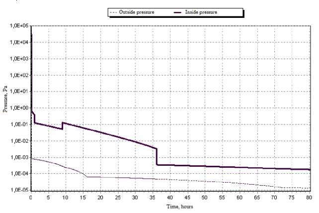
Рис. 1. Предварительные зависимости внешнего давления и давления в негерметичном приборном отсеке КА от времени в начальный период летной эксплуатации
Fig. 1. Preliminary dependencies on time for the outside pressure and for the non-hermetic equipment bay pressure at the beginning of the flight
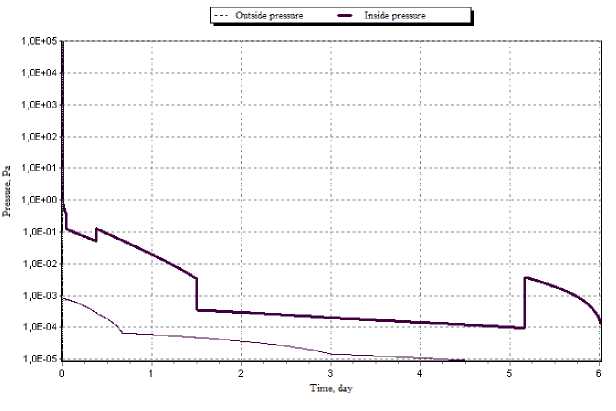
Рис. 2. Предварительные зависимости внешнего давления и давления в негерметичном приборном отсеке КА от времени в первые 6 суток летной эксплуатации
Fig. 2. Preliminary dependencies on time for the outside pressure and for the non-hermetic equipment bay pressure during the first 6 days of the flight
Pressure dynamics monitoring equipment
To monitor the pressure dynamics inside UPIM during flight operation, a pressure sensor unit (PSU) jointly developed by ISS JSC and Novosibirsk State University was integrated into the geostationary spacecraft.
PSU provides pressure measurement from 790 to 1∙10–8 mm Hg.
The PSU unit uses two sensors to measure pressure: a semiconductor sensor based on MEMS technology (micro-electromechanical system) for operation in the range from 790 to 1∙10–4 mm Hg and an inverse magnetron sensor with a cold cathode for operation in the range from 1∙10–3 to 1∙10–8 mm Hg.
A semiconductor sensor based on MEMS technology (Fig. 3) is a high-precision meter of the thermal conductivity of the gas under study. The value of heat conductivity depends on the gas pressure acting on the sensor, since a decrease in pressure leads to a decrease in the gas concentration at the sensor surface, which, in turn, leads to reduce of transfer of heat from one working part of the sensor to another.
The cold cathode inverse magnetron sensor (Fig. 4) used in PSU measures absolute pressure by ionizing the residual gas in the working volume of the sensor. The cylindrical body of the sensor is used as a zero-potential cathode. During operation, a voltage of more than 1500 V is applied to the anode located in the center of the sensor. The magnetic system keeps free electrons in the sensor area, forcing them to move along the epicycloids inside the working volume of the sensor. When electrons collide with molecules of the residual gas, the molecules are ionized. Ions, when interacting with the cathode, cause the emission of secondary electrons, the current of which is proportional to the ion current.
Switching of sensors is performed automatically when the pressure reaches 1.4 10–4 mm Hg. The PSU measurement error is 20% at a pressure in the range from 790 to 1∙10–4 mm Hg and 50% in the range of 1∙10–4 to 1∙10–8 mm Hg.
The PSU is located inside UPIM on the instrument panel. The location of the PSU in the spacecraft is shown in Fig. 5.
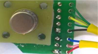
Рис. 3. Полупроводниковый датчик на основе МЕМС-технологии
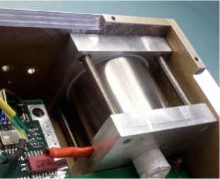
Рис. 4. Инверсно-магнетронный датчик
Fig. 4. Inverse magnetron sensor
Fig. 3. Semiconductor sensor based on MEMs technology
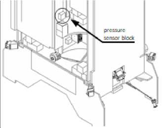
Рис. 5. Размещение БДД в составе КА (сотовая панель не показана)
Fig. 5. Pressure sensors block inside the spacecraft (honeycomb panel is not shown)
The results of measurements of pressure dynamics in the UPIM
In accordance with the flight test program, the pressure was measured at the spacecraft launch site. On fig. Figure 6 shows a graph of the pressure drop inside UPIM SC №2 during the launch phase. The initial flat shelf on the graph is the measurement of atmospheric pressure from the moment of PSU initialization to the moment of launch of the launch vehicle. A more detailed pressure change under the nose cone and inside the UPIM in the launch area is shown in Fig. 7.
The measured pressure inside the UPIM corresponds to the calculated values of the pressure drop under the nose cone. After separation from the launch vehicle, the pressure dropped sharply. When the main engines (ME) of the Breeze-M upper stage are turned on, an increase in pressure is recorded for the duration of the engines operation. A short-term increase in pressure was recorded when the additional fuel tank (AFT) was released and the spacecraft was separated. The value of pressure at the moment of separation of the spacecraft from the launch vehicle (separation contact - SC), calculated by the PKDYN software, developed by the Moscow Aviation Institute, and the measured one coincided.
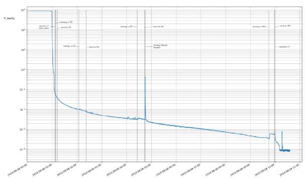
Рис. 6. График спада давления внутри негерметичного приборного отсека в течение участка выведения на КА № 2
Fig. 6. Pressure drop graph inside the non-hermetic equipment bay during the launch for spacecraft № 2
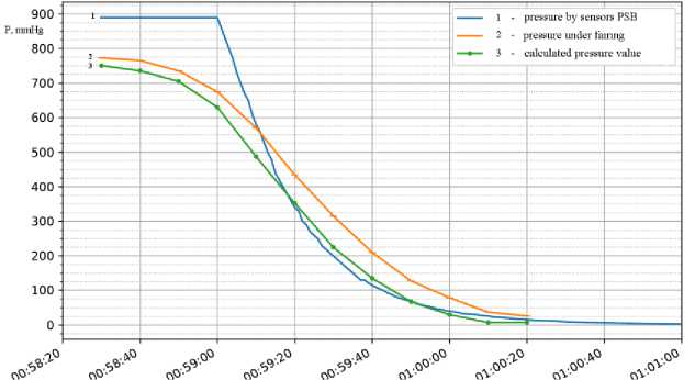
Рис. 7. График спада давления под обтекателем и внутри негерметичного приборного отсека в течение первых 120 с полета РН
Fig. 7. Pressure drop graph inside the fairing and inside the non-hermetic equipment bay for the first 120 sec of the launch vehicle flight
Measurement of pressure dynamics after SC
The value of the measured pressure and the temperature of the panel inside the UPIM of spacecraft № 1 for the period from SC (12/21/2018) to 11/21/2019 is shown in Fig. 8. The graph shows the data: pressure - blue (upper curve), panel temperature - green (lower curve).
An analysis of the measurement results shows that the pressure inside the UPIM depends on the temperature of the UPIM panels. As a result of the increase in temperature inside the NGPO, the processes of gas release of on-board equipment materials are intensified and, consequently, the pressure increases. This dependence is shown in more detail in Fig. 9, which shows the values of pressure (blue curve) and temperature (red curve) in the period from February 3 to February 10, 2019. During this period of time, a private program was carried out on SC No. 1 to test the thermal control system. After shutting down both fluid circuits, the temperature in the PSU area increased to 30 ºС, as a result of which the pressure briefly increased to 10-4 mm Hg.
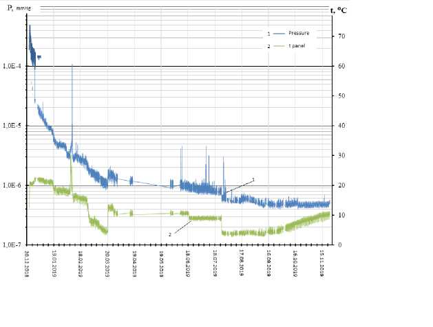
Рис. 8. График спада давления (верхняя синяя кривая) и температуры (нижняя зеленая кривая) внутри негерметичного приборного отсека на КА № 1
Fig. 8. Pressure (upper blue line) and temperature (lower green line) drop graph inside the non-hermetic equipment bay for spacecraft № 1
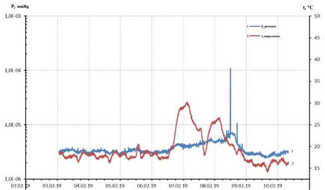
Рис. 9. Давление и температура в период с 3 по 10 февраля 2019 г.
Fig. 9. Pressure and temperature between 3th and 10th February 2019
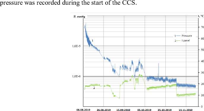
Figure 10 shows a graph of the pressure drop (blue curve) and the panel temperature (green curve) inside the UPIM on spacecraft No. 2. The dynamics of the pressure drop on spacecraft No. 1 and 2 is the same. On spacecraft no. 2, the dependence of pressure on the temperature of the panel is also visible.
Figure 11 shows calculated pressure drop values and readings from two pressure sensors: a semiconductor sensor based on MEMS technology (pressure sensor 1) and an inverse magnetron cold cathode sensor (pressure sensor 2). The calculated values are given in accordance with the mathematical model. At the time of SC, the calculated pressure value and the measured one coincide. Further, there are some discrepancies. In accordance with the calculations, there should be a significant increase in pressure when the conversion and control system (CCS) and the airborne relay complex (ARC) are turned on. However, only a slight increase in pressure from 2∙10–6 to 4∙10–6 mm Hg was noted on spacecraft No. 1 during the test runs of the ARS from January 20 to February 2, 2019. No increase in
Date
Рис. 10. График спада давления и температуры внутри негерметичного приборного отсека на КА № 2
Fig. 10. Pressure and temperature drop graph inside the non-hermetic equipment bay for spacecraft № 2
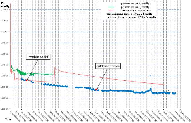
Рис. 11. Расчетные значения спада давления (красная кривая) и показания БДД: полупроводниковый датчик на основе МЕМС-технологии (зеленая кривая) и инверсно-магнетронный датчик (синяя кривая) на КА № 1
-
Fig. 11. Pressure drop calculated values (red line) and pressure sensors block data: semiconductor sensor based on MEMs technology (green line) and inverse magnetron sensor (blue line) for spacecraft № 1
Similar results of measurements of the pressure drop dynamics inside UPIM were recorded on spacecraft No. 2 (Fig. 12). The ARC was switched on on August 11, 2019 at a pressure of ~ 2∙10-5 mm Hg, the inclusion of ARC was 09/02/2019 at a pressure of ~ 2∙10-6-6 mm Hg, which corresponded to the permitted pressure range declared in the design documentation for the inclusion of this equipment.
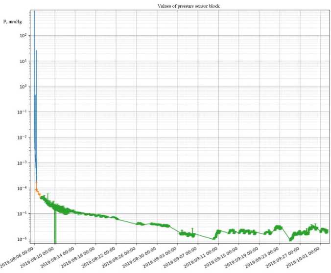
Рис. 12. Спад давления на КА № 2
-
Fig. 12. Pressure drop for spacecraft № 2
Conclusion
In the course of the work carried out, for the first time, the dynamics of pressure drop in an unpressurized compartment for a spacecraft was experimentally determined by a certain structural layout of the scheme from the moment of launch to the start of use for its intended purpose in natural conditions. At present, the information array contains data for 2 years and 9 months of operation.
Flight tests confirmed the correctness of the choice of types of sensors to perform the task. Confirmed the ability to conduct continuous pressure measurements in the range from 790 to 10–7 mm Hg. The sensitivity of pressure sensors allows to record pressure changes when the temperature changes ~ 5 ºС.
The time values for passing the critical pressure region for the onboard equipment sensitive to this parameter, located inside the UPIM, are determined, which allows to optimize the program for turning on high-voltage equipment and significantly reduce the time to turn on the payload at full power.
The verification of the calculation model showed that:
-
– there are some discrepancies between the calculated pressure values and the measured ones. Thus, it is necessary to correct the model of pressure drop and the formation of OEA within the UPIM;
-
– no increase in pressure was recorded during the CCS activation, which indicates about the correctness of the design of the ventilation holes in the body of the UPIM;
-
– a significant increase in pressure during the inclusion of the ARC was not recorded, which due to the correct use of materials with a mass loss of not more than 1%, the implementation of outgassing processes in the manufacture of on-board equipment units, and the slowing down of degassing processes in oil and gas production facilities.
Long-term monitoring of the pressure dynamics inside the UPIM showed that this parameter, with a given design and layout scheme with a certain set of ventilation holes, reached an equilibrium stationary mode within six months and the pressure in the UPIM is ~10–6 mm Hg.
References Pressure measurement inside non-sealed equipment bay of the geostationary spacecraft
- Maksimov I. A., Kochura S. G. Issledovanie vliyaniya faktorov kosmicheskogo prostranstva i tekhnogennykh faktorov na kosmicheskie apparaty, razrabotka metodov i sredstv zashchity [Study of the influence of space factors and man-made factors on spacecraft, development of methods and means of protection]. Krasnoyarsk, 2011, 182 p.
- Maksimov I. A. [Problems of ensuring the reliable functioning of modern spacecraft in condi-tions of the destabilizing effect of space factors and man-made factors]. Vestnik SibGAU. 2010, No. 4(30), P. 100–102 (In Russ.).
- Nadiradze A. B., Maksimov I. A., Smirnov V. A. [Experimental study of the polluting effect of its own external atmosphere at the stage of orbital operation of the spacecraft]. Vestnik SibGAU, 2006, No. 1(8), P. 91–95 (In Russ.).
- Nadiradze A. B., Chirov A. A., Shaposhnikov V. V. [Estimation of the degassing time of the leaking instrument compartment of the spacecraft]. Vestnik SibGAU. 2007, No. 1 (14), P. 95–98 (In Russ.).
- Maksimov I. A., Smirnov V. A., Ivanov V. V. [Increasing the reliability of the leaky compart-ment of the spacecraft]. Vestnik SibGAU. 2007. No. 1 (14). P. 88–90 (In Russ.).
- Nadiradze A. B., Parshina E. B., Shaposhnikov V. V. [Experimental determination of the pollut-ing and erosive effects of jets of electric rocket engines on materials of spacecraft]. Materialy 4-oy mezhdunarodnoy konferentsii “Aviatsiya i kosmonavtika – 2005” [Materials 4 Intern. Scientific. Conf. “Aviatsiya i kosmonavtika – 2005”]. Moscow, 2005, P. 1 (In Russ.).
- Nadiradze A. B., Shaposhnikov V. V., Arbatskiy V. M. [Mathematical modeling of contamina-tion of outer surfaces of a spacecraft by exhaust of electric rocket engines and components of its own external atmosphere]. Materialy chetvertogo mezhdunarodnogo aerokosmicheskogo kongressa [Mate-rials of the fourth international aerospace congress]. Mosсow, 2003, P. 1 (In Russ.).
- Ivanova T. A., Pavlov N. N., Reyzman S. Ya. [Monitoring of the radiation situation in the geo-stationary orbit at the maximum of the 23rd solar cycle]. Materialy 3-y Vserossiyskoy nauchnoy kon-ferentsii “Fizicheskie problemy ekologii” [Materials of the 3rd All-Russian Scientific Conference “Physical Problems of Ecology”]. Mosсow, 2001, Vol. 6, P. 8 (In Russ.).
- Vlasova N. A., Getselev I. V., Ivanova T. A. [Monitoring the radiation situation on high-apogee spacecraft]. Materialy V mezhotraslevoy nauchno-tekhnicheskoy konferentsii “Elektrizatsiya kosmich-eskikh apparatov i sovershenstvovanie ikh antistaticheskoy zashchity kak sredstva uvelicheniya nadezh-nosti i srokov aktivnogo sushchestvovaniya” [Materials of the V interdisciplinary scientific and technical conference “Electrification of spacecraft and improvement of their antistatic protection as a means of increasing the reliability and terms of active existence”]. Korolev, 2002, p. 1. (In Russ).
- Sosnovets E. N., Panasyuk M. I., Vlasova N. A. [Modeling and monitoring of the radiation sit-uation in the Earth's magnetosphere on high-apogee spacecraft]. Materialy konferentsiya po fizike solnechno-zemnykh svyazey “Solnechno-zemnaya fizika” [Materials conference on the physics of so-lar-terrestrial relations “Solar-terrestrial physics”]. Irkutsk, 2002, Vol. 2 (115), P. 1 (In Russ.).
- Maksimov I. A., Prokop’ev Yu. M., Khartov V. V. [Creation of a monitoring system for exter-nal influencing factors arising from the operation of the spacecraft]. Materialy Chetvertogo mezhdu-narodnogo aerokosmicheskogo kongressa [Materials of the Fourth International Aerospace Congress]. Moscow, 2003, P. 1 (In Russ.).
- Krylov A. N., Mishina L. V., Chudina N. A. [Dynamics of pressure changes in leaky compartments of satellites in geostationary orbits]. Aviatsionnoe priborostroenie. 2006, No. 3, P. 55–58 (In Russ.).
- Nadiradze A. B., Shaposhnikov V. V., Khartov V. V. Modelirovanie protsessov formirovaniya SVA i zagryazneniya poverkhnosti KA [Modeling the processes of formation of NEA and contamina-tion of the spacecraft surface]. Moscow, 2007.
- Novikov L. S., Sovremennoe sostoyanie i perspektivy issledovaniy vzaimodeystviya kosmich-eskikh apparatov s okruzhayushchey sredoy, Vvedenie, Model' Kosmosa, vos'moe izdanie. Tom 2. Vozdeystvie kosmicheskoy sredy na materialy i oborudovanie KA [Current state and prospects of re-search into the interaction of spacecraft with the environment, Introduction, Model of the Cosmos, eighth edition. Vol. 2. The impact of the space environment on materials and equipment of the space-craft]. Moscow, 2007.
- Smirnov V. A., Shatrov A. K., Maksimov I. A. [Investigation of the polluting effect of its own external atmosphere and plasma of stationary plasma engines on the Express-AM spacecraft]. Vestnik SibGAU. 2006, No. 2(9), P. 46–50. (In Russ.).
- Absalamov S. K. Measurement of plasma parameters in the stationary plasma thruster (SPT-100) plume and its effects on spacecraft components. 28th Joint Propulsion Conference and Exhibition. Nashive. 1992.
- Rantanen R. O., Bareiss L. E., Ress E. B. Determination of Space Vehicle Contamination. Proc. Of Centre Natianal D’Etudes Spatiales Symphosium on Evaluation of Space Environment on Materials, held at Toulouse. France. P. 211–232.
