Применение группы беспилотных летательных аппаратов для обнаружения радиоизлучающих средств

Автор: Дмитриев Д.Д., Гладышев А.Б., Ратушняк В.Н., Михов Е.Д.
Журнал: Журнал Сибирского федерального университета. Серия: Техника и технологии @technologies-sfu
Рубрика: Радиолокация и радионавигация
Статья в выпуске: 7 т.18, 2025 года.
Бесплатный доступ
В настоящее время, учитывая бурное развитие радиотехнических систем различного назначения, важнейшим организационным мероприятием для обеспечения их электромагнитной совместимости является своевременное обнаружение мешающих радиоизлучающих средств (РИС) и определение их местоположения. Для решения этой задачи применяются пространственно- разнесенные системы радиотехнического мониторинга и контроля электромагнитной обстановки, одним из основных недостатков которых является ограничение их дальности действия дальностью прямой видимости. Устранение данного недостатка возможно за счет модификации такой системы радиотехнического мониторинга – применения группы беспилотных летательных аппаратов (БПЛА), осуществляющих ретрансляцию сигналов РИС на наземный пункт приема и обработки данных (ППОД). Однако в такой системе должна быть решена проблема высокоточной навигации БПЛА как между собой, так и относительно ППОД. В статье предложены два метода улучшения точности измерения координат БПЛА применительно к подобной системе радиотехнического мониторинга. Первый – это метод измерения взаимных координат БПЛА и ППОД, основанный на использовании единого созвездия навигационных космических аппаратов; второй – применение дальномерного метода измерения дальности от ППОД до БПЛА, позволяющий уточнить их координаты, а также с высокой точностью измерить расстояния от ППОД до БПЛА.
Обнаружение радиоизлучающих средств, пространственно-разнесенная система радиотехнического мониторинга и контроля электромагнитной обстановки, группа беспилотных летательных аппаратов, взаимная навигация, единое созвездие навигационных космических аппаратов, дальномерный метод измерения дальности
Короткий адрес: https://sciup.org/146283212
IDR: 146283212 | УДК: 621.396.96
Use of a Group of Unmanned Aerial Vehicles to Detect Radio-Emitting Devices
Currently, there is a rapid development of radio engineering systems for various purposes, which causes the problem of their electromagnetic compatibility. To solve this problem, the most important organizational measure is the timely detection of interfering radio- emitting devices and determination of their location. For this purpose, spatially distributed systems of radio engineering monitoring and control of the electromagnetic environment are used. The main disadvantage of such systems is the limitation of the range of action by the line of sight. This drawback can be eliminated by modifying the spatially distributed radiotechnical monitoring system – using a group of unmanned aerial vehicles (UAVs). These UAVs relay signals from radio- emitting devices to a ground- based data reception and processing item. However, such a system must solve the problem of high- precision navigation of UAVs both among themselves and relative to the data reception and processing station. The article proposes two methods for improving the accuracy of UAV coordinate measurement in relation to such a radiotechnical monitoring system. The first is a method for measuring the mutual coordinates of the UAV and the data reception and processing point, based on the use of a single constellation of navigation spacecraft; the second is the use of a rangefinder method for measuring the distance from the data reception and processing point to the UAV, which allows specifying their coordinates, as well as measuring the distances from the data reception and processing point to the UAV with high accuracy.
Текст научной статьи Применение группы беспилотных летательных аппаратов для обнаружения радиоизлучающих средств
Благодарности. Исследование выполнено за счет гранта Российского научного фонда № 25–19– 20070, –19–20070/, гранта Красноярского краевого фонда науки.
Цитирование: Дмитриев Д. Д. Применение группы беспилотных летательных аппаратов для обнаружения радиоизлучающих средств / Д. Д. Дмитриев, А. Б. Гладышев, В. Н. Ратушняк, Е. Д. Михов // Журн. Сиб. федер. ун-та. Техника и технологии, 2025, 18(7). С. 931–939. EDN: HVZASI but also the impact of unintentional interference on the receiving paths along the side and back lobes of the antenna system directional patterns. Minimizing such negative influence requires the use of a set of organizational and technical measures. One such measure may be to use interference compensation systems, the effectiveness of which depends on knowledge of the location of the source of the interference signal.
To determine the location of radio-emitting devices, spatially distributed systems of radio-technical monitoring and control of the electromagnetic environment are used, consisting of several spatially distributed base stations (receiving points). At these base stations, angle-measuring or rangemeasuring methods are used to determine the location of radio-emitting devices. Angle-measuring methods require the use of highly directional multi-beam antenna systems based on antenna arrays, which seriously complicates the design of base stations [1]. Recently, such systems have actively used differential-range methods. The essence of these methods is that the signal from radio-emitting devices is received at no less than three spatially distributed points and the delay between the received signals is measured using basic-correlation methods. The coordinates of radio-emitting devices are calculated based on the measured delays between the received signals at different receiving points, taking into account their known location [2].
Such radio-technical monitoring systems have two serious drawbacks that significantly limit their widespread use. The first drawback is that their range is limited by the line of sight. At the same time, the line of sight requirement applies to all spatially distributed receiving points, which is difficult to implement in real terrain and urban development. The second disadvantage is the need for high-precision synchronization of receiving points with each other, as well as the possible ambiguity in determining the location of radio-emitting devices when using only three receiving points.
To eliminate the first drawback, retransmission of signals of radio-emitting device via low-orbit or geostationary spacecraft has been actively used recently [3–5]. This method is quite effective and provides practical coverage of large areas with a radio monitoring system. However, it is limited to the detection and localization of satellite communication stations that affect the receiving paths of spacecraft with signals that are unintentional interference, along the side lobes of both the emitting antenna of the ground station and the receiving antenna of the spacecraft [4]. Also, considering the fairly large distances from the ground-based radio-emitting device to the repeater placed on the spacecraft, using this method it is possible to detect fairly powerful radio-emitting devices – satellite communication stations, radio beacons, etc.
To detect signals from low-power radio-emitting devices at ranges exceeding line-of-sight, many scientific groups propose placing repeaters on UAVs of the aircraft, multicopter type, or tethered balloons [6, 7]. In addition, the trend of using UAVs as part of organized groups is currently actively developing, due to which a synergistic effect can be achieved – simultaneous monitoring of large areas, the possibility of using small and medium-class UAVs instead of heavy ones, etc. Next, we will consider the issues of using UAVs in spatially distributed radio monitoring systems in order to increase their range.
1. Using a group of UAVs to increase the range of a radio monitoring system
To increase the range of action, you can propose the use of an UAV multicopter type or binding balloons that allow you to increase the height of the receiving points and increase the range of visibility. However, a straightforward decision to raise the reception center as a whole meets the following great technical difficulties:
-
– limited carrying capacity of flights;
-
– high energy consumption of reception centers requiring the organization of power supply from ground power sources;
-
– the need for a high-precision topographic binding of receiving points, since the accuracy of determining the location of radio emitters directly depends on it.
To eliminate the above deficiencies, it is proposed to modify the standard scheme of the spatially distributed system of radio engineering monitoring by placing repeater radio signals on several UAVs (multicopter type or binding balloons) (Fig. 1).
UAVs-repeater
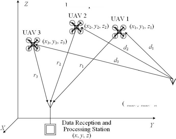
Radio-Emitting Devices {XRED- У red- -red)
Fig. 1. Modification of the system of radio-technical monitoring
In this case, the signals from radio-emitters devices with coordinates ( x RED , y RED , z RED ) are accepted by repeater located on UAV 1, 2, 3 with coordinates ( x i , y i , z i ), where i is the number of UAV. Further, the signals are transmitted to the ground data receipt and processing station, while each UAV is allocated its own frequency range on the UAV – data receipt and processing station.
The following operations are performed at the data receipt and processing station:
-
– basic-correctional processing of the accepted signals of radio-emitting device;
-
– the delays in the radio signals taken by individual UAVs are determined;
-
– the coordinates of radio-emitting device are calculated.
Since it is impossible to directly measure the distances from the UAV-repeater to the radioemitting device, then to find its coordinates ( x RED , y RED , z RED ) use the diverse-dial method based on the measurement of the distances Δ d j 1 between the radio emitter device and the UAVs:
d (^^^^ d- 2 J d3 -d{ = Ad3l
where Δ d i 1 is the difference in distances from the radio-emitting device to the i -th UAV, i = 2, 3, 4; Δ d i 1 = с×τ i 1 ; τ i 1 – the difference in the arrival of the same signal sales on the 1st and i -th UAV-repeater; c – speed of light.
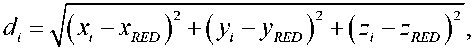
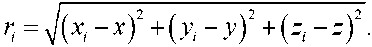
Distances d i from the radio-emitting device to the i -th UAV and the distance r i from the i -th UAV to the data of the receipt and processing station are determined by formulas known from the theory of radio navigation:
The delays in the reception time of the radio signal are determined by calculating the function of mutual correlation between each pair of signals emitted by the radio-emitting device and the data accepted at the reception and processing station. Then they are converted into the difference in the distances of two compared UAV-repeater relative to the radio-emitting device.
Based on the calculation of the difference in the values of the signal receipt (distances) in pairs, hyperbolic lines of the position of the radio emittering device are determined, and the signal source will be at the intersection of two hyperbol (Fig. 2).
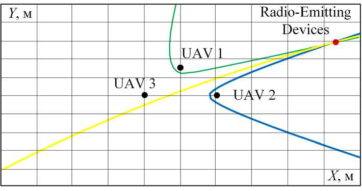
Fig. 2. Determining the location of the radio-emitting device using the diverse-dial method
From the analysis of formulas (1)-(3) it can be seen that for the implementation of the diverse-dial method in the proposed spatially distributed system of radio-technical monitoring, the coordinates of each UAV-repeater must be measured with high accuracy. This distinguishes it from the known methods for determining the location of radio emitting devices using satellite retransters [4, 5], in which the coordinates are known.
2. Improving the accuracy of determining the location of the UAV
Given the limited capabilities of UAVs in terms of payload and power supply of onboard systems, GNSS receivers are used for their navigation support almost without alternative. They allow for an error in measuring coordinates using code measurements of less than 10 m, and using differential – 935 – modes or Real Time Kinematic (RTK) – less than 1 m [8]. In cases where high accuracy of coordinate measurement of radio-emitting devices is not required, then coordinate measurements with such an error are quite sufficient [7]. However, the implementation of the differential mode requires the presence of differential correction stations transmitting information about corrections to onboard GNSS receivers, which is difficult to implement in hard-to-reach regions. The use of GNSS receivers in UAVs, integrated with high-precision inertial navigation systems, significantly complicates the onboard navigation system, increases its weight, dimensions and energy consumption.
For closely located GNSS receivers, the external components of the error – ephemeris, tropospheric, ionospheric, etc. will be practically the same. It is on this fact that the use of differential modes is based. However, the main condition for the operation of differential modes is the presence of differential correction stations, the coordinates of which are measured with high accuracy using astronomical methods. But even under these conditions, the measurement error of the coordinates of mobile GNSS receivers based on code measurements is 20…30 cm. The use of a data reception and processing station as a differential correction station is possible, but its equipment will be significantly more complicated. It will require the use of a high-precision multisystem dual- or triple-frequency GNSS receiver, a weather station, a quantum frequency and time standard, and other technical and organizational measures to determine both its own coordinates and calculate differential corrections with high accuracy. Mobile GNSS receivers placed on UAVs are also significantly more complex. In addition, one of the main problems in implementing such operating modes is the need to organize communication channels for transmitting differential corrections, which also causes an increased load on the UAV onboard equipment.
Considering that the UAV and the data receiving and processing station can be considered as an organized group, as an alternative, we can propose a combined use of two methods for improving the accuracy of measuring the UAV coordinates. The first method is measuring the mutual coordinates of the UAV and the data receiving and processing station, based on the use of a single constellation of navigation spacecraft. The second method is the use of a rangefinder method for measuring the distance from the data receiving and processing station to the UAV, which allows us to refine their coordinates and measure the distances d i between them with high accuracy.
The key feature of the first method is that for two closely located GNSS receivers, the total components of the errors in determining pseudoranges that are external to the GNSS receiver are practically identical, provided that the same constellation of navigation spacecraft is used, the signals of which are used to solve the navigation problem. This leads to the fact that both GNSS receivers experience similar shifts when determining their coordinates, and the calculation of mutual coordinates, that is, the difference in coordinates between the data receiving and processing station and the i-th UAV Δx = x – xi, allows for compensation of these error components. As a result, the most significant impact on the accuracy of coordinate measurement is exerted by the noise and hardware components of the error, depending on the specific GNSS receiver. This method does not impose significant requirements on computing resources and the communication channel. In the data transmitted from the data receiving and processing station to the UAV, it is sufficient to transmit the composition of the constellation of navigation spacecraft used and its coordinates measured in autonomous mode [9, 10]. The results of experimental studies of this method show that, despite the simplicity of implementation, its application reduces the standard deviation of the measurement of mutual coordinates of GNSS – 936 – receivers by approximately two times – from 0.92 to 0.43 m, their abrupt changes caused by the difference in the constellations of navigation spacecraft are eliminated (Fig. 3) [11]. In addition, given that the data receiving and processing station is stationary, it is possible to improve the accuracy of measuring mutual coordinates by accumulating and averaging measurements of its coordinates over a long period of time.
To implement the second method of improving the accuracy of coordinate measurement, no modification of the UAV onboard equipment is required. The essence of the method is to organize a local range-finding radio navigation system, with the data receiving and processing station being used as the only beacon, and measurements of the distances to all UAVs will be made relative to it. Let us consider the organization of such a system in more detail.
The data receiving and processing station generates and emits a broadband signal modulated by a ranging code based on the M-sequence or its variations (Gold, Kasami codes, etc.). Repeaters placed on the UAV receive this signal, transfer it to the frequency band allocated for each repeater, and emit it in the direction of the data receiving and processing station (Fig. 4). The data receiving and processing station receives the retransmitted rangefinding signal and, using (4), calculates the range to the UAV:
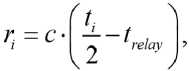
where ti is the delay time from the moment of emission of the ranging signal to the moment of its reception; c is the speed of light; trelay is the delay time of the ranging signal in the repeater.
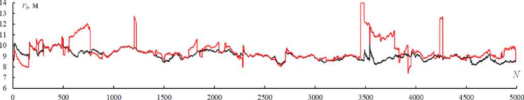
Fig. 3. Results of ri measurements from the data receiving and processing station to the UAV using autonomous measurements (red) and using a single constellation of navigation spacecraft (black)
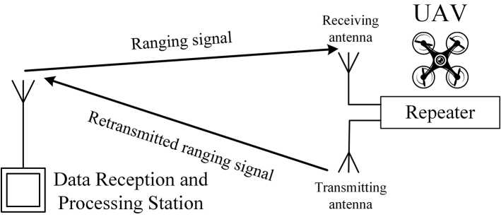
Fig. 4. Rangefinding method for measuring distances between a data receiving and processing station and a UAV
The frequency values of the ranging signal emitted by the data receiving and processing station can be selected in the operating frequency ranges of the GNSS or the system for detecting signals from radio emitting devices. To eliminate the mutual influence of the GNSS signals and the ranging signal of the data receiving and processing station, its frequency is in a frequency band free of standard satellite radio navigation signals of standard accuracy [12]. Taking the bandwidth of the range-measuring signal of the data reception and processing station equal to 5 MHz (1593…1598 or 1605…1610 MHz), we obtain an achievable error in measuring the range, comparable to the error in measuring coordinates by GNSS receivers using high-precision signals. In addition, in the proposed structure of the radio monitoring system, CDMA signals can be used as a ranging signal. In this case, if the modulating function of the ranging code of the signals of the data receiving and processing station differs from that used in the modulation of signals of satellite navigation systems, then any frequency of the emission of the signals of the models can be selected within the permitted frequency range.
Conclusion
Thus, the use of UAV groups in spatially distributed systems of radiotechnical monitoring and control of the electromagnetic environment for retransmitting signals from radio-emitting devices allows for a significant increase in their range. However, one of the main problems hindering the mass application of this method is the need for high-precision measurement of the UAV coordinates relative to the data receiving and processing station, which directly affects the accuracy of determining the location of radio-emitting devices. The combined use of two proposed methods for improving the accuracy of UAV coordinate measurement – a method based on the use of a single constellation of navigation spacecraft, and a rangefinding method for measuring the distance from the data receiving and processing station to the UAV – allows for a significant reduction in the error in determining the location of radio-emitting devices using existing hardware with insignificant computational costs.
