Printed Text Character Analysis Version-III: Optical Character Recognition with Noise Reduction, Background Detection and User Training Mechanism for Simple Cursive Fonts

Автор: Satyaki Roy, Ayan Chatterjee, Rituparna Pandit, Kaushik Goswami
Журнал: International Journal of Information Engineering and Electronic Business(IJIEEB) @ijieeb
Статья в выпуске: 2 vol.7, 2015 года.
Бесплатный доступ
The present system performs analysis of snapshots of cursive and non-cursive font character text images and yields customizable text files using optical character recognition technology. In the previous versions the authors have discussed the user training mechanism that introduces new non-cursive font styles and writing formats into the system and incorporates optimization, noise reduction and background detection modules. This system specifically focuses on enhancing the process of character recognition by introducing a mechanism for handling simple cursive fonts.
Cursive font handling mechanism, Resizing Algorithm, Character broken lines, Noise Reduction, Background Detection
Короткий адрес: https://sciup.org/15013337
IDR: 15013337
Текст научной статьи Printed Text Character Analysis Version-III: Optical Character Recognition with Noise Reduction, Background Detection and User Training Mechanism for Simple Cursive Fonts
Published Online March 2015 in MECS
New font styles are introduced everyday and the existing optical character recognition softwares are outdated since they are unable to incorporate the new fonts. Therefore in the previous versions we have discussed the user training mechanism that would give the user the ability to introduce new graphic symbols as per his or her requirements. The given system can therefore update itself with any new unknown graphic symbol.
In the second version we have proposed three things that the system has incorporated (i) a noise handling module to minimize salt and pepper noise and handle text images which have poor quality or poor lighting (ii) we have an optimization module in place that would ensure that process of character recognition can be optimized by minimizing the number of comparisons. (iii) And finally the system also has a novel binary conversion with background detection module which is able to differentiate between the character symbol and the image background making the process of recognition a lot simpler. All these mechanisms were applicable for noncursive fonts only.
However in the third version of the system we are focusing on cursive fonts because the process of character recognition is only complete when our system is extended to handle irregular and cursive fonts. It is needless to say that the process of character recognition tends to become complicated when we consider cursive fonts because there are no clear demarcations for characters when it comes to cursive font and the point of contact between two characters for cursive fonts can be variable.
Printed Text character analysis is fundamentally different from the existing literature on optical character recognition. Mori and Suen, in literature [1], have proposed the concept of template analysis whereas our system is based on the concept of pixel matching algorithm. Mantas, in [2], shows that a system should have the pre-processing and recognition techniques in place that would cope with online and offline character recognition techniques. The system now has a greater reach in terms of the variety of characters or graphic symbols it can handle and it ensures a greater degree of flexibility and efficiency in character recognition with the inclusion of cursive font recognition.
-
II. System Modules
This system has two distinctive modules:
-
- The User Training Module
As mentioned before, the User Training Module is allows the user to train the system to recognize new characters and font styles. We shall see that the user training module is same for the cursive and non-cursive fonts.
-
- The Character Recognition Module
The Character Recognition module actually performs the recognition of characters. It uses the character dictionary (discussed later) as the database to recognize the characters from a text image. It must be remembered the character recognition module here is going to be slightly different for cursive fonts and non-cursive fonts.
I nsertion or Training Module
Read image to be trained 4 Monochrome Conversion
Noise Reduction
Boundary Detection 0
Independent Scaling
Fix pattern generation
Resize Algorithm
Insert into database
Character Recognition Module
Read Image to be recognized D
Monochrome Conversion
Noise Removal
Line and space detection cursive or non-cursive character extraction
Independent Scaling
Fix pattern generation
Resize and Compare
Write to file.
Fig. 1. System Modules
Figure 1 (above) demonstrates the system components and we shall discuss them in greater details in the next section.
-
III. Details Of System Implementation
-
A. Monochrome Conversion
In [3] Maloo and Kale, have discussed the concept of separation of foreground and background called binarization. Monochrome conversion, which serves the very same purpose, has been divided into three stages-
-
(i) . Grayscale Conversion
The prime objective of this module is to reduce the number of colors in the image. We know that grayscale images only provide shades ranging from black (generally denoted by 0) to white (generally denoted by 255). This module would therefore assist the system in detecting the difference between character pixels and background pixels. Typically character pixels have shades closer to black and background pixels have shades closer to white.
The grayscale conversion algorithm works in the usual way by extracting every pixel value 'px' and finds its red, green and blue components and replaced the R, G and B values of 'px' by the average of the red, green and blue components denoted by 'avg'. In the algorithm shown, px1 is the converted pixel
for every pixel 'px' in the text image ‘IMG’, alpha = (px>>24)& 0xff;
avg = (red+green+blue)/3
px1 = (alpha<<24) + (avg<<16) + (avg<<8) + avg
-
(ii) . Binary Conversion
At this stage, it is imperative to bring down the number of possible shades from 256 to 2. This would ensure that the process of character recognition can be simplified.
The working of this module is described below-
Let variable ‘n’ hold the number of shades for a grayscale image and ‘x’ and ‘y’ are counter variables for the image.
Let “shades” be the 1-D array that has all the possible grayscale values.
Variable k covers the first half of the “shades” array i.e. shades closer to black and variable k2 covers the rest.
The variables ‘mx’ and ‘my’ are the image size along x and y axis.
Step 1: Define k = 0
Step 2: Define k1 = k + n/2 + 1
Step 3: Define x = 0
Step 4: Define y = 0
Step 5: Extract pixel px at position (x, y)
Step 6: If px = shades [k] then make px black
Step 7: If px = shades [k1] then make px white
Step 8: Increment y. If y is less than my then GOTO 5
Step 9: Increment x. If x is less than mx then GOTO 4
Step 10: If k is less than nosh/2 GOTO 3
Step 11: End
-
(iii) . The New Background Detection Mechanism
This is a new feature of the second version. Optical character recognition systems are unable to handle text images where the foreground and background colors are very similar. Therefore this mechanism of background detection would ensure that the system recognizes the background color. The foreground or the character pixels are made black whereas the background color is made white, irrespective of the original foreground and background colors of the image.
The first extracted pixel is the top left pixel. It is considered the background pixel. If “Firstpix” is 255 (or white), the foreground and background remain unchanged else the foreground and background colors are swapped using the variable “Newpix”. Therefore the character pixels are always black and the background pixels are always white.
Step 1: If Firstpix = 255 then let every pixel remain unchanged
Step 2: If Firstpix < 255 make every black pixel white and white pixel black
Step 3: End
-
B. Noise handling mechanism
Sometimes noisy images are hard to read and character recognition becomes very difficult in the presence of salt and pepper noise.
The system makes use of median noise filter module which removes any blotches of noise and also prevents the possible blurring of edges.
Consider the 3 X 3 (left) image matrix given below –
|
20 |
18 |
20 |
|
10 |
20 |
21 |
|
22 |
20 |
20 |
|
20 |
18 |
20 |
|
10 |
100 |
21 |
|
22 |
20 |
20 |
Fig. 2. The working of the median filter
(As shown on the right) after arranging the elements in ascending order we have 10, 18, 20, 20, 20, 20, 21, 22 and 100. Therefore the median element is 20. We replace the central pixel with the median element.
From the matrix (on the left) we can clearly tell that the central pixel is disparate i.e. noisy. Therefore we use the median of the pixel values to replace the central pixel.
Fig. 3. Original Image with specks of noise on the left and the image after noise removal on the right.
We have encountered a few variants of the median filter. The primary objective of the median filter module is to handle impulse noise, salt-and-pepper noise as discussed in [4]. Our system implements a very simple form of median noise filter and its effectiveness is shown in the test cases later.
Working of Noise Handling Module-
The variable size refers to the size of the window of consideration. In our case it is 3 X 3 =9.
Step 1:Define size = size of window, b = floor ((window size)/2)
Step 2:Define h= image height, w = image width
Step 3: i=b
Step 4: j=b
Step 5: Define array a [size], variable cnt = 0
Step 6: k=i-b
Step 7: l= j-b
Step 8: a [cnt] = IMG [l] [k], increment cnt
Step 9: Increment l. If l is less than or equal to (j + b), GOTO 8
Step 10: Increment k. If k is less than or equal to (I + b), GOTO 7
Step 11: Sort array a in ascending or descending order Step 12: IMG [j] [i] = a [size/2]
Step 13: Increment j. If j is less than or equal to (w-b), GOTO 5
Step 14: Increment i. If i is less than or equal to (h-b), GOTO 4
Step 15: End
-
C. Boundary detection
Now let us understand how the system differentiates a cursive character from a non-cursive font. The system employs a threshold aspect ratio value ‘maxAsp’. We know that the aspect ratio is the ratio between the width and height of the extracted character.
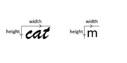
Fig. 4. Aspect Ratio (= width / height) for cursive font (left) and noncursive font (right)
As evident from Figure 4, the aspect ratio of a cursive font is generally greater than the aspect ratio of the noncursive character because the width of the cursive font is greater. Therefore if the aspect ratio of the extracted character exceeds the threshold value ‘maxAsp’, we invoke the cursive character recognition module. Now we shall discuss the boundary extraction modules for the cursive and non-cursive fonts.
-
(i) . Non-Cursive Font Handling Module
This is the most significant component in the system. This section deals with the identification of the character boundaries. This process is very crucial as more effective the boundary recognition, better is the quality of character extraction. The underlying principle behind the recognition of character boundary is the positioning and alignment of the dark (character) pixel values.
This non-cursive font algorithm extracts four character boundaries for every line of written text:
-the Vertical Top Line
-the Vertical Bottom Line
-Horizontal Left Character Line
-Horizontal Right Character Line
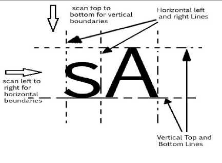
Fig. 5. The non-cursive character boundary extraction process
As mentioned before the character boundary extraction is a key component in both the modules i.e. user training and character recognition.
With the help of figure 4, let us see how this component works. Remember with the help of the boundary recognition module, all character pixels are black and background pixels are white.
The first target here is to determine the vertical top and bottom character boundaries. These boundaries together demarcate a line of printed text.
Vertical Top Boundary Line Extraction
Step 1: Define variable x = 0 and y = starting row ‘st’
Step 2 : Define y = 0
Step 3: Define x = 0
Step 4 : If IMG [x] [y] = 0 then RETURN value of y
Step 5 : Increment x. If x less than the width of image GOTO 4
Step 6 : Increment y. If y less than the height of image GOTO 3
Step 7 : End
If we have an image matrix 'IMG [x] [y]' where 'y' is the row of the image matrix and 'x' is the column of the matrix, we scan downwards from the start row number 'st' (where st is initially set to 0 and otherwise represents the previous vertical bottom character line). As soon as it detects a pixel value which equal to 0, it considers the row to be the Vertical Top Character line and returns the row 'y'.
For the Vertical Bottom Boundary extraction, the same process is repeated, only this time, the downward scanning starts from top boundary line. Therefore st = Vertical Top Boundary Line.
Horizontal Left Boundary Line Extraction
Step 1: Define variable x = 0 and y = 0
Step 2: Define x = Horizontal Left Boundary
Step 3: Define y = Vertical Top Boundary
Step 4: If IMG [x] [y] = 0 then RETURN value of x
Step 5: Increment y. If y less than the height of image GOTO 4
Step 6: Increment x. If x less than the width of image GOTO 3
Step 7: End
If we have an image matrix 'IMG [x] [y]' where 'y' is the row of the image matrix and 'x' is the column of the matrix, we scan left to right from the leftmost pixel. As soon as it detects a pixel value which is equal to 0 it considers the column to be the Horizontal Left Character line and returns the column 'x'.
For the Horizontal Right Boundary extraction, the same process is repeated, only this time, the left to right scanning starts from left boundary. Therefore (initially) x =horizontal left character boundary.
-
(ii) . Cursive Font Handling Module
The system initially employs the non-cursive character boundary extraction mechanism. If the aspect ratio of the character exceeds ‘maxAsp’ it invokes the cursive font handling module. The extraction of the cursive character is based on the process of scanning the cursive word column-wise and counting the minimum number of black pixels in each column, as shown in Figure 6.1.
Step 1: Extract the number of black pixels in every column (in variable ‘pixcnt’) of the extracted character window and store it in array ‘arr1’ where lchar and rchar are the left and right boundaries and horUpLine and horDownLine are the top and bottom boundaries of extracted cursive word-
Define array ‘arr1’
For j=lchar to rchar
Variable pixcnt = 0
For i = horUpLine to horDownLine if IMG [j] [i] = 0 Increment pixcnt
End for arr1[cn] = pixcnt
Increment cn
End for
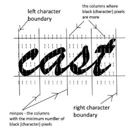
Fig. 6.1. Cursive Boundary Extraction
Step 2: As Figure 6.1 suggests, the entries of the array ‘arr1’ refer to the number of dark pixels in every column.
The column(s) that has the minimum number of dark pixels (i.e. minpos in Figure 6.1) is the possible points of contact between two characters in the cursive word. The columns with the minimum number of pixels are registered in the array ‘arr2’. Here ‘minval’ is the minimum number of dark pixels and the array ‘arr2’ stores the column index of all such columns with minimum black pixels.
Define minval=arr1[0]
For i=1 to cn do if arr1 [i] < minval then minval= arr1 [i]
end if end for
For i= 0 to cn do
If arr1[i] = minval
Arr2[ leng] = i + lchar
Leng = leng + 1
Ignore all the consecutive entries of ‘minval’ because they represent the continuous connecting strokes between two characters
End for
Step 3: Now we are performing the process of character extraction from a cursive word by employing the array ‘arr2’. As shown in Figure 6.2 we can extract characters c, a, s and t from the cursive word. For example the first estimated character ‘c’ is between arr2 [0] and arr2 [1], the second estimated character ‘a’ is between arr2 [1] and arr2 [2].
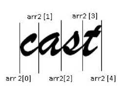
Fig. 6.2. Every columns of minimum number of dark pixels are stored in the array ‘arr2’
A character after extraction is stored in a binary pixel string ‘pix’, resized and matched with the existing database entries. For example if a ‘pix’ pattern between arr2 [0] and arr2 [1] is not a match, we consider a pix pattern between arr2 [0] and arr2 [2]. If again there is no match the system considers the space between arr2 [0] and arr2 [3]. This continues until a match is found or rchar is encountered.
-
D. Binary Pixel Pattern Generation
Once the character boundary has been recognized, the system generates the binary pixel pattern which is a binary string that stores the pixel values lying within the window of the character boundaries.
As we have mentioned before, in the pixel pattern ‘pix’, character pixels are represented by 0 and background pixels are represented by the value 1.
Step 1: Define i = Vertical Top Boundary
Step 2: Define j = Horizontal Left Boundary
Step 3: If IMG [j] [i] = 0 then append 0 to string pix else append 1.
Step 4: If j <= Right Boundary then GOTO 3
Step 5: If i <= Bottom Boundary then GOTO 2
Step 6: End
This binary pixel pattern is resized and stored in the database called the character dictionary for character matching process.
-
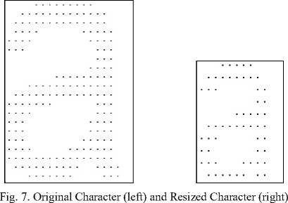
E. Resize Algorithm
In [5] Mithe, Indalkar and Diveka have discussed normalization techniques to ensure uniform size of characters and smooth recognition of characters. After extraction and generation of the binary pixel pattern ‘pix’, the extracted character is resized to a default value of 10 x 10. This ensures a few things:
-
- It helps the pixel-wise character matching process, because every character is reduced to the same size.
-
- It reduces memory overhead because 100 character values are stored for each character.
-
- It speeds up the matching process because the time taken to perform 100 comparisons is not very high.
The resizing algorithm works on the principle of mapping. It simply scales down a matrix of certain pixel size to a 10 x 10 matrix. We would like to point out here that the size of 10 X 10 is not fixed.
We have experimentally determined that we are obtaining an optimum performance and quality with the 10 X 10 binary strings. If the window size is increased then the time to perform character recognition will also be quite high.
In the resizing algorithm below:
The values ‘h1’, ‘w1’ are the height and width of the original binary pixel matrix, whereas both ‘h2’ and ‘w2’ are set to 10 (which is the size of the reduced or resized pixel matrix). The resized character matrix is stored in 1-D array ‘temp’.
Step 1: Define w1 = Image width, h1 = Image height
Step 2: Define w2 = 10, h2 = 10
Step 3: Define 1-D array ‘a’ which stores original pixel string
Step 4: Define x_ratio = w1/w2, y_ratio = h1/h2
Step 5: Define i = 0
Step 6: Define j = 0
Step 7: Define px = j * x_ratio, py = i * y_ratio
Step 8: temp [(i*w2)+j] = a [ (int)((py*w1)+px)]
Step 9: Increment j. If j less than w2 then GOTO 7
Step 10: Increment i. If i less than h2 then GOTO 6
Step 11: End
-
F. Independent Character Scaling
There is another small task which remains to be done after the extraction of characters. When there are two characters adjacent to each other that have varying heights, then the character which is shorter tends to have a white space on top as evidenced by figure 8 shown below.
white space
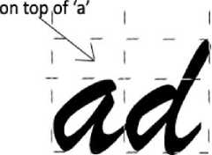
Fig. 8. The white space on top of character ‘a’ that exists because‘d’ has a greater height
The independent character scaling algorithm simply removes the white space on any character after extraction. This is very important for accurate character recognition.
-
G. Storage into character dictionary
It is very important to store the pattern for a certain character for future reference as proposed in [6]. To do that, the database called character dictionary is the mainstay of the User Training Mechanism. Once the binary pixel pattern has been generated for a certain character, the pixel pattern is transferred to the character dictionary. In our algorithm we have used a MS Access database but any other data storage can be utilized. The dictionary has the following fields:
-
- Character name
-
- Binary Pixel Pattern String
-
- Aspect Ratio (to be used for optimization purposes as discussed later)
Table 1. Character Dictionary Sample for character ‘a’
|
Character Name |
Binary Pixel String 100 pixel values |
Aspect Ratio |
|
A |
11111000111… |
1.1818 |
It must be remembered that the system already has a character dictionary in place. The advantage here is that the user may add new characters to the dictionary with the user training module and introduce new writing styles at his will. The character dictionary is not a predictive mechanism to correct instances of misspellings as proposed in [7]. It would only make the process of character recognition more accurate.
-
H. Comparison and Matching Algorithm
This technique of character recognition/ matching works with the pixel matching method where the corresponding 10 X 10 values of the extracted pixel pattern is resized and matched against the pixel pattern of the character dictionary. If the number of matched pixels exceeds a threshold value (generally set to 85 out of 100 pixels) we can call it successful character recognition. The simplistic matching algorithm is described here,
Step 1: Take one character entry in the dictionary, define counter = 0
Step 2: Define i = 0
Step 3: Extract pix_a = ith pixel of the extracted character
Step 4: Extract pix_b = ith pixel of the database entry Step 5: If pix_a = pix_b then counter = counter +1 Step 6: i = i +1, if i less than 100 GOTO 3
Step 7: If counter is greater than or equal to 85, then the match is successful.
Step 8: GOTO 1 until the end of database is reached
Step 9: End
The comparison and matching algorithm also includes an additional mechanism that would handle characters that are not clearly printed due to poor image resolution or lighting.
Fig. 9. The incomplete print of extracted character ‘b’.
As you can see in Figure 9, the character b, after extraction is not clearly printed. However our system uses a mechanism where it ignores the rows which have no black pixels. Therefore the character recognition is based on the pixel matching of the remaining rows. Therefore the system recognizes the character ‘b’ without difficulty despite its poor print.
-
I. Newline and Space Detection
We must understand that merely recognizing characters is not enough. The system must be able to detect end of character lines and spaces in between characters as well. Therefore we have a separate mechanism to recognise newlines and spaces.
-
- Newline Detection: Previously we have spoken about the recognition of the Horizontal Right Character Boundary and the Vertical Bottom Character Boundary.
The algorithm works as follows:
If the right boundary returns -1, it indicates end of line.
If bottom boundary returns -1, it indicates end of the page.
-
- Space Detection: If the algorithm detects a gap of atleast 10 pixel columns between adjacent characters, it considers the gap to be a space. The value of 10 pixel columns has been determined experimentally.
-
J. Optimization Mechanism
The optimization strategy is an instrumental part of the system design in the second version of printed text character recognition. The prime objective of the OCR system is to ensure that the character recognition is brisk and efficient. In order to maintain the speed of recognition, the character matching process must be optimized. The present system makes use of a few subtle techniques like aspect ratio test and first-row comparison testing.
Aspect Ratio Test- The aspect ratio takes advantage of the fact that the aspect ratio is an integral part of the character which remains same irrespective of the size of character. The system performs a match of aspect ratio at the beginning of the matching process. A drastic mismatch in the ratio causes the system to ignore the database entry and move on to the next entry for a given extracted character.
First-row Comparison Test- This testing mechanism compares the first row of the database 10x10 pixel matrix with the first row of current character pixel values. A blatant mismatch would cause the control to shift to the next database entry. It must be remembered that by first row we mean the first 10 pixel values.
Here is a snippet that explains the working of the aspect ratio test
Step 1: Extract the next character in the database
Step 2: Define asp = aspect ratio for the extracted character
Step 3: Define asp = aspect ratio for the database entry Step 4: Define t = asp – dd
Step 5: If absolute value (t) > 0.2 then the aspect ratios are different so skip the database entry
Step 6: GOTO 1
Step 7: End
-
IV. Overall System Algorithm
We have just discussed the independent components of the system. Now let us discuss the overall algorithm we have implemented in the system.
Brief system algorithm for Insertion Module –
Step I: Read image- IMG of graphical symbol or character to be trained to the system
Step II: Convert IMG to its monochrome equivalent with black and white spades
Step III: Apply the noise handling mechanism
Step IV: Extract the boundary of the character to be trained.
Step V: Calculate the aspect ratio = width/height for the character for optimization.
Step VI: Create the binary pixel pattern generation.
Step VII: Resize the extracted character and store the information in the character dictionary.
Step VIII: End
Brief system algorithm for Character Recognition Module –
Step I: Read image- IMG of graphical symbol or character to be recognized.
Step II: Convert IMG to its monochrome equivalent with black and white spades
Step III: Apply the noise handling mechanism
Step IV: Extract boundary for every character or cursive word that is encountered.
Step V: Calculate aspect ratio = width/height for the character for optimization.
Step VI: Create the binary pixel pattern generation and resize the character
Step VII: Perform top and bottom independent scaling of character
Step VIII: Apply the comparison algorithm with the optimization mechanism to recognize the character Step IX: If match is found print character and space (if necessary).
Step X: GOTO step IV for the extraction and recognition of the next character.
Step XI: End
-
V. Working Of The System
In our previous versions [8] and [9] we have discussed the working of the user training module for the noncursive font. Here we are discussing the same modules for the cursive fonts.
The working of both the modules have been briefly illustrated in the following sections A and B, by applying them on a character images-
-
A. Working for the User training module
We have shown the steps involved in the training module using the character ‘a’.
Step 1: The user may use the User Interface to upload an image of the character he wishes to introduce into the character dictionary. The character image is converted into the corresponding grayscale and monochrome.

Fig. 10. Insert image of character to be trained
Step 2: The boundary is recognized and character is extracted (Figure 11).
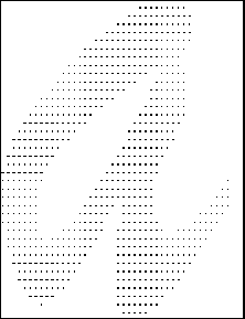
Fig. 11. Character after boundary recognition and extraction.
Step 3: The character is resized and independently scaled (Figure 12).

Fig. 14. The image for recognition
Step 2: The individual characters are identified. In this case the characters ‘a’ and‘d’ are recognized as shown below and subsequently resized.
Fig. 15. The binary matrix for the extracted character‘d’ where 1 represents background (white) and 0 represents character (black) pixels.
Step 3: At this point we also use the optimization mechanism which skips the pixel-wise comparison when the database entry does not have a similar aspect ratio as the extracted character.
character=a
Fig. 12. The character is resized
Step 4: The extracted character is inserted into the character dictionary. The user training process is complete.
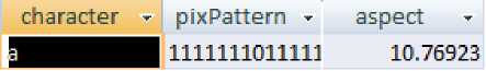
Fig. 13. Character ‘a’ inserted into database
-
B. Working for the Character Recognition Module
Step 1: The image is uploaded for character recognition (Figure 14).
pixel patterns111111101111111000011111000011
Sill001101011010001000011001100011
aspect ratiosi0.76923
asp=7.5 dd=10.76923 t=-3.2692300000000003
IGNORING!!!!ee
-
Fig. 16. Optimization process where the aspect ratio of the extracted character does not tally with that of the database entry. Hence the system ‘ignores’ the current database entry ‘a’. Here the variable t is the absolute value of the difference between the extracted character aspect ratio and the database entry aspect ratio.
As shown in Figure 16, the database entry is ‘a’ and its aspect ratio is not the same the extracted character, therefore the comparison is skipped. This is the example of the optimization process.
pixel pattern=1111111111111111111011111111001 0111001100011110101011011001100011 aspect ratio=8.135593
asp=7.5 dd=8.135593 ±=-0.6355930000000001
FI HAL FERCEh-A<5E = 92.22222222222223
-
Fig. 17. Successful character match
As depicted in Figure 17, for every character whose boundary is recognized, we perform a match with a database entry. (In figure 17, after extraction we find a 92 percent match with a database entry of‘d’ even though the percentage match may be as low as 80 percent).
Step 4: The process of character recognition continues until all the characters are recognized. In figure 18, we have a printed text with only two characters.
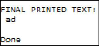
Fig. 18. Final printed text
-
VI. Test Results
In this section we shall consider all the examples of successful character recognition of rare text images.
In the four cases discussed below, successful character recognition is possible because of the four new modules introduced in this version namely (i) cursive font handling mechanism (ii) noise handling mechanism (iii) background detection mechanism and (iv) optimization mechanism.
Table 2. Special Test Cases with description, text image and final printed text (below)
|
Nature of Test Case |
Text Image |
Final Printed Text |
||||
|
Test Case I: In figure 19, there is a character image where parts of the characters are missing (broken lines) is recognized by the system. This is possible to the additional mechanism used in the compare or matching algorithm that ignores the rows with no character pixels. |
lines are not clear Fig. 19. Test Case 1 |
lines are not clear |
||||
|
Test Case II: In figure 20, we have the successful recognition of simple cursive font with the help of the cursive font recognition module |
« е<м 4ue twe Fig. 20. Test Case 2 |
u can sue me |
||||
|
Test Case III: In figure 21, we show the successful recognition of simple cursive font with the help of the cursive font recognition module |
CAAt ей V<f Fig. 21. Test Case 3 |
cast is very good |
||||
|
Test Case IV: In figure 22, we take an image with the almost same foreground and background color which makes it almost impossible to distinguish. Recognition is made possible due to the monochrome and background detection module. We have the original image (left) and the image after monochrome conversion (right). |
t,16 cdw Fig. 22. Test Case 4 |
see the color |
||||
|
Test Case V- In test case 5, we have a poor quality image – This image is noisy. However our system is able to recognize the characters successfully because of the application of the noise detection module. |
this is a poor ■ quality image do u pee it ■ Fig. 23. Test Case 5 |
this is a poor quality image do u see it |
|
Test Case VI – In figure 24, there is a low Light Image – Another example of the effectiveness of the noise detection module. |
all the world is a stage Fig. 24. Test Case 6 |
all the world is a stage |
|
Test Case VII- In figure 25 a high Resolution Image is considered- The process of character recognition is quick because of the optimization module |
the present system addresses a few key aspects of optical character recognition technology existent systems are hardcoded in terms of the fonts and writing styles they can accommodate it not only reduces the shelf life of the system but also makes processing large text documents a cumbrous task Fig. 25. Test Case 7 |
the present system addresses a few key aspects of optical character recognition technology existent systems are hardcoded in terms of the fonts and writing styles they can accommodate it not only reduces the shelf life of the system but also makes processing large documents a cumbrous task |
VII. Conclusion And Future Scope
Our system has been designed in java using the PixelGrabber class to read text images as described in [10] and [11]. The fundamentals of image processing used character detection and recognition are referred from the book of Gonzalez, Woods and Eddins [12].
The present system can handle a variety of fonts and writing styles. We have incorporated a variety of features like the user training, optimization, noise reduction, background detection and simple cursive font handling modules to render flexibility to the process of optical character recognition. However the system can be improved greatly to handle more irregular and cursive fonts with more erratic points of contact.
Acknowledgement
We are grateful to the Department of Computer Science, St. Xavier’s College, Kolkata for giving us the unique opportunity of working on the project. We wholeheartedly thank the 2012-14 batch of M.Sc. Computer Science for their support and encouragement.
Список литературы Printed Text Character Analysis Version-III: Optical Character Recognition with Noise Reduction, Background Detection and User Training Mechanism for Simple Cursive Fonts
- Mori S, Suen C Y and Yamamoto K,"Historical review of OCR research and development", Proceedings of IEEE 80, pp. 1029–1058, 1992.
- J. Mantas,"An overview of character recognition methodologies", Pattern Recognition Volume 19, Issue 6, pp. 425–430, 1986.
- Mamta Maloo, K.V. Kale, "Gujurati Script Recognition: A Review", International Journal of Computer Science Issues, Vol. 8 Issue 4 No. 1, pp. 480-489, July 2011.
- Kwame Osei Boateng, Benjamin Weyori Asubam, David Sanka Laar, "Improving the Effectiveness of the Median Filter", International Journal of Electronics and Communication Engineering Volume 5 No. 1 (2012) pp 85-87.
- Ravina Mithe, Supriya Indalkar, Nilam Divekar, "Optical Character Recognition", International Journal of Recent Technology and Engineering (IJRTE) Volume 2 Issue 1, pp. 72-75, March 2013. Nick Efford, "Digital Image Processing a Practical Introduction using Java"- Pearson Education.
- Sukhpreet Singh, "Optical Character Recognition Techniques: A Survey" Journal of Emerging Trends in Computing and Information Sciences, Vol. 4, No. 6 June 2013.
- Youssef Bassil, Mohammad Alwani, "OCR Post-Processing Error Correction Algorithm Using Google's Online Spelling Suggestion", Journal of Emerging Trends in Computing and Information Sciences, Vol. 3 No.1, pp. 90-99, January 2012.
- Satyaki Roy, Ayan Chatterjee, Rituparna Pandit, Kaushik Goswami, "Printed Text Character Analysis Version-I: Optical Character Recognition with the new User Training Mechanism", International Journal of Advanced Computer Research, Volume 4 No. 2 Issue 15 June, 2014.
- Satyaki Roy, Ayan Chatterjee, Rituparna Pandit, Kaushik Goswami, "Printed Text Character Analysis Version-II: Optimized optical character recognition for noisy images with the new user training and background detection mechanism", International Journal of Advanced Computer Research Volume 4 No. 2 Issue 15 June, 2014.
- Herbert Schildt, "Java- The Complete Reference, 8th Edition", McGraw-Hill Companies.
- Kwame Osei Boateng, Benjamin Weyori Asubam, David Sanka Laar, "Improving the Effectiveness of the Median Filter", International Journal of Electronics and Communication Engineering Volume 5 No. 1 (2012) pp 85-87.
- Gonzalez, Woods and Eddins, "Digital Image Processing Using Matlab", Gatesmark Publishing.
