Проект крупного солнечного телескопа с диаметром зеркала 3 м

Автор: Григорьев В.М., Демидов М.Л., Колобов Д.Ю., Пуляев В.А., Скоморовский В.И., Чупраков С.А.
Журнал: Солнечно-земная физика @solnechno-zemnaya-fizika
Статья в выпуске: 2 т.6, 2020 года.
Бесплатный доступ
Абстракт. Одной из наиболее актуальных проблем современной физики Солнца являются наблюдения мелкомасштабной структуры солнечной атмосферы на разных уровнях (включая хромосферу и корону) и в разных спектральных линиях. Такие наблюдения возможны только с использованием крупных солнечных телескопов с диаметром основного зеркала не менее трех метров. В настоящее время в мире в процессе разработки или создания находятся несколько масштабных проектов таких крупных солнечных телескопов. В России начиная с 2013 г. ведется разработка отечественного крупного солнечного телескопа с диаметром зеркала 3 м (КСТ-3), который является составной частью Национального гелиогеофизического комплекса РАН. Планируется, что телескоп будет расположен в Саянской солнечной обсерватории на высоте более 2000 м. Выбор был сделан в пользу классической осесимметричной оптической схемы Грегори с альт-азимутальной монтировкой. Научное оборудование КСТ-3 будет состоять из нескольких систем узкополосных перестраиваемых фильтров и спектрографов на разные диапазоны длин волн и размещаться как в основном фокусе куде на вращающейся платформе, так и в фокусе Несмита...
Солнце, корона, телескоп, пространственное разрешение, магнитные поля, поляризация, спектрограф, спектральные линии
Короткий адрес: https://sciup.org/142224295
IDR: 142224295 | УДК: 523.9, | DOI: 10.12737/szf-62202002
Project of the large solar telescope with mirror 3 m in diameter
One of the most important problems of modern solar physics is the observation of the small-scale structure of the solar atmosphere at various heights (including the chromosphere and corona) in different spectral lines. Such observations can be made only with large solar telescopes whose main mirror has a diameter of at least 3 m. Currently, several large solar telescopes are under construction or development in the world. In 2013 in Russia, the work began on the development of a national large solar telescope with a mirror 3 m in diameter (LST-3), which is a part (subproject) of the National Heliogeophysical Complex of the Russian Academy of Sciences. The telescope is planned to be located in the Sayan Solar Observatory at an altitude of more than 2000 m. The choice was made in favor of the classic axisymmetric Gregory optical layout on an alt-azimuth mount. The scientific equipment of LST-3 will consist of several systems of narrow-band tunable filters and spectrographs for various wave ranges. The equipment will be placed both in the main coude focus on a rotating platform and in the Nasmyth focus. To achieve a diffraction resolution, high-order adaptive optics (AO) will be used. It is assumed that with a certain modification of the optical configuration, LST-3 will work as a 0.7 m mirror coronograph in near infrared lines and can also be used for observing astrophysical objects in the nighttime.
Текст научной статьи Проект крупного солнечного телескопа с диаметром зеркала 3 м
Historical notes
Solar physicists have always dreamt of creating large solar telescopes. It was natural since they understood that basic physical processes occur in thin atmospheric layers of the Sun; hence the need for the telescopes capable of making measurements with a spatial resolution comparable to the mean free path of a photon and a temporal resolution comparable to the typical scale of changes in the gas dynamics of the solar atmosphere.
Solar physicists of Europe, U.S., and Russia have worked on projects of large solar telescopes since the mid-20th century. It is obvious that the implementation of the projects depends on financial and technological resources. In U.S., a 4 m telescope DKIST (Daniel K. Inouge Solar Telescope) has been under construction for many years [Rimmele et al., 2010; McMullina et al., 2013]; and just recently (January 2020) it has given preliminary observations (first light). A project of 4 m tele- scope is under development in Europe [Sánchez-Capuchino et al., 2010]; a 8 m telescope with a ringshaped mirror (Chinese Giant Solar Telescope) is under design in China [Liu et al., 2013]. A large solar telescope with a 3 m aperture LST-3 is currently under preliminary design in Russia. The dream of such a telescope has a long history.
In the 1980s, the Commission of Multilateral Cooperation of Academies of Sciences of Socialist Countries on the complex problem of Planetary Geophysical Research (KAPG) approved the theme "Development of Scientific and Technical Problems Associated with the Creation of Joint Solar Observatory of Socialist Countries". The main instrument of the observatory was to be a large solar telescope with the main mirror at least 2 m in diameter. In 1986, KAPG working group 4-1.1 under the guidance of Corresponding Member of the Academy of Sciences of the USSR Stepanov V.E. prepared a document "Scientific and Technical Proposals for Joint Solar Observatory". In 1989, Academician G.I. Marchuk, President of the Academy of Sciences of the
This is an open access article under the CC BY-NC-ND license
USSR, sent letters to Presidents of Academies of Sciences of the socialist countries. All of them supported the establishment of such an observatory and sent representatives from their Academies of Sciences. The political events of the early 1990s stopped the constructive process. Complex instruments for astroclimate research had, however, been designed and manufactured, pilot studies of a number of sites in Uzbekistan, Turkmenistan, Tajikistan, and Dagestan had been carried out, and promising sites to be more thoroughly explored had been projected.
The cooperation of the KAPG working group with the Carl Zeiss Jena Company and the Leningrad Optical and Mechanical Association (LOMO) was aimed at developing the concept of the large solar telescope and system of small instruments. By discussing and analyzing merits and demerits of completely vacuum telescopes and fully open telescopes, the working group came to the concept of partially vacuum tower solar facility. The Carl Zeiss Jena Company (H. Artus) provided a draft design of the telescope with a specific and effective way of weather protection of its optical system.
In the late 1990s, the initiative engineering study of the large telescope began again. ISTP SB RAS researchers and LOMO engineers proposed a new concept of a large alt-azimuth telescope. They suggested using the classical Gregory system with an additional flat mirror as an entrance aperture. The system combined advantages of coelostat systems of horizontal solar telescopes and symmetrical alt-azimuthal system. This concept was presented at the 1st All-Russian Conference in 2001 in St. Petersburg [Grigoryev et al., 2001] and in the special session of the 26th Conference of the International Astronomical Union in 2006 in Prague [Grigor'ev et al., 2006] .
In 2013, financing was provided and work started on the engineering design of the Large Solar Telescope with a mirror 3 m in diameter (LST-3), which is a part of the National Heliogeophysical Complex of the Academy of Sciences.
General requirements for the telescope
The main purpose of LST-3 is to gain new information on the fine structure of magnetic fields in different layers of the atmosphere from the deepest to the corona. At the same time, a detailed study of plasma processes in the solar magnetic field should help to address many fundamental problems of not only solar physics but of interplanetary space physics as well, and to give insight into solar-terrestrial relations and phenomena on other stars. The LST-3 spatial resolution is assumed to be 0.1"; the spectral resolution, 300 000 in a range from 0.4 to 3 µm; the instrumental scattering light in the coronagraph mode, ~5·10–6 of the photospheric intensity at a distance from the limb R / R =1.15 in the infrared (IR) range; the instrumental polarization, <10 %.
Thus, to provide high spatial, spectral, and temporal resolutions of the solar structure on the disk and in the corona requires a telescope with a 3 m high-polished main mirror. To monitor the Sun, a 3 m heavy mirror cannot be installed in the classical equatorial mount — only on an alt-azimuthal (horizontal) mount, which en- sures optimal weight reducing of the telescope, its mirrors, and drive operation. Large focal instruments (spectrographs, filtrographs) are placed under the telescope on a platform, which rotates with the telescope following the Sun, to provide a stationary position of solar image in receivers.
When constructing the solar telescope, we should keep in mind heat problems. Mirrors are exposed to solar heat, which may degrade image quality of the telescope. The main requirement for the thermal regime is that temperatures of all surfaces of the telescope should be as close as possible to the ambient temperature, preferably by 1–2 K lower. The main mirror reflects more than 5000 W, the impact of this heating is difficult to eliminate, so we should reduce the useful field of the telescope by an order of magnitude, using heat stop. It is important to choose a correct passive weight-reducing system for mirrors, presumably mechanical and pneumatic, which does not create tension in the mirrors that leads to surface deformation, especially in large mirrors prone to thermal and gravitational changes. The active mechanical system should be aimed at correcting the residual deformation of the main mirror. Necessary data on the shape of the mirror surface for this purpose can be obtained from wavefront sensors of the adaptive system, designed for rapid correction of solar image distortions occurring at different heights of Earth’s atmosphere. Influences of temperature gradients on the image quality in the air immediately above the optical surface can be restricted by sweeping of heated or cooled air from the mirror surface by an “air knife”.
The choice of the axial outside focal Gregory optical system for LST-3, in which the secondary mirror is located behind the focus of the main mirror, is due to better protection from ambient light illumination and better capabilities for temperature control. The installation of the heat stop in the main focus of the mirror makes it possible to limit the light flux incident on the secondary mirror, and consequently, in the subsequent optical system. It becomes possible to make observations, using a Lyot coronagraph with internal occultation.
The telescope is planned to be located in a tower 30 m in height, 20 m in diameter, with a dome analogous to the DKIST dome. The tower will be equipped with a lift shaft, with adjoining three-storeyed technical building.
SCIENTIFIC PURPOSESOF LARGE SOLAR TELESCOPES
Scientific purposes change, of course, over time — new objectives appear due to telescope observations and development of solar physics. The telescope should, therefore, be designed so as to be adapted to new scientific challenges. Bellow, we present objectives of LST-3, which can be formulated in terms of requirements of modern solar and solar-terrestrial physics.
Nature of magnetic fields and solar activity cycle
In solar physics, it has always been necessary to achieve a high spatial resolution in order to solve important scientific problems. At present, the study of the fine structure continues to be relevant. Today, the concept of high resolution has a wider meaning and includes high spatial (0.1–0.2 arcsec), temporal (<1 s), and spectral (~10 mÅ) resolutions.
A typical time scale of processes in the solar photosphere determined by height of the homogeneous atmosphere and by the speed of sound, is of the order of 10 s. Even smaller estimate of the order of 1 s follows from considerations of radiative relaxation. Problems with temporal resolution inevitably arise also when adaptive optics is used because the time scale of turbulence in Earth’s atmosphere is <<1 s.
The requirements for spatial, temporal and spectral resolutions are likely to be connected in the Stokesmetry and diagnostics of the fine structure of solar magnetic fields. Magnetic field vector measurements require high spatial resolution, probably even higher than in intensity measurements. This need arises from the nonlinear dependence of polarization in the line on magnetic field orientation. Spatially averaged profiles of Stokes parameters give a magnetic field vector that may differ significantly from the spatially averaged true magnetic field.
To understand the physics of solar activity and solar variability requires us to understand how magnetic fields are generated and dissipate on the Sun. The nature of the 11-year sunspot cycle and the 22-year cycle of the global magnetic field is still not fully clear. We should note that only a small fraction of the energy (10–5), produced by thermonuclear processes in the solar core, is converted into the energy of the solar magnetic field, although it is the magnetic field that drives all dynamic phenomena on the Sun. Imagine what happens on other stars, where the total magnetic field is more than 1000 times stronger than the total magnetic field of the Sun. Generation of the magnetic field or dynamo on the Sun and stars is still fraught with puzzles.
Current dynamo models explaining the behavior of large-scale magnetic fields of the Sun are based on mean-field theories. Key parameters such as diffusivity and helicity, which are incorporated in these models and related to small-scale processes, are, however, not measured.
Three-dimensional simulation of turbulent flows with large Reynolds number indicates that each scale of turbulent motions gives rise to its own magnetic field scale system. While the computer simulation of such complex processes does not always adequately reflect the physical nature of the interaction between plasma motion and magnetic field, it raises many questions to be answered by observations. How do weak and strong magnetic fields interact? Why do magnetic elements of the fine structure have mainly one polarity in large areas of the solar surface? Whether the large-scale magnetic field is associated with coherent properties of the fine structure or coherent properties of the small-scale structure define the large-scale field? It makes no difference for the mean-field theories but is crucial for the physics of solar magnetic fields. What contribution do magnetic fields of different scales make to the chromosphere and corona magnetism and their heating?
These questions can be answered only by means of a large telescope capable of resolving the structure of individual flux tubes and observing their emergence, development, and disappearance.
For the problem of weak large-scale magnetic fields on the Sun and their connection with small-scale magnetic elements to be solved, it is important to measure magnetic fields in the IR spectrum range with a large telescope. Using the Zeeman splitting in the FeI1.565 µm line in the lower photosphere and in the MgI12 µm line in the upper photosphere, we can measure a magnetic field weaker than 100 G. These lines can be utilized to estimate the height variation of the magnetic field strength to the region, where the magnetic energy exceeds the kinetic energy of gas and the magnetic field breaks free of the influence of plasma motion.
The IR region is a natural spectral region, where we can study magnetic fields because the ratio of the Zeeman splitting to the line width is proportional to the wavelength. Advances in IR-receiver technologies open up a new era in the study of solar magnetic fields. It has become possible to observe profiles of Stokes parameters in the wavelengths, where the lines are much more sensitive to the Zeeman splitting as compared to the visible region. This especially relates to high-order Rydberg emission lines, which near 12 µm exhibit a normal Zeeman splitting, which exceeds the line width in the range of field strengths of ~300 G.
It seems relatively simple to obtain parameters of the magnetic field vector from measurements of Stokes profiles at 12 µm, without many difficulties occurring at shorter wavelengths. The limitations are, however, due to the mechanism that generates emission in these lines and is not yet fully understood, although it may be associated with nonthermal processes.
A bright coronal line SiIX3.932 µm has recently been discovered in the IR region; in addition, there are other lines in the near-infrared region. If optics of the large telescope and its design is made so as to provide a level of scattering light of <0.5 %, the telescope will work in the coronograph mode. This, of course, imposes high requirements for polishing the mirror, but if the telescope works in the IR region, they will not be much different from the standard requirements for polishing mirrors.
The light scattered by mirror microroughness is inversely proportional to the square of the wavelength, i.e. ~λ–2. In the green region, requirements are generally imposed for coronagraph mirrors such that the root mean square (RMS) of the roughness does not exceed 3–5 Å — in the IR region this corresponds to 20–40 Å (the standard requirement for astronomical mirror quality). The coronograph mode of the large telescope in the IR range gives a unique possibility of measuring magnetic fields and motions in the corona with high spatial resolution.
The most interesting results are to be expected from studies of magnetic fields below the photosphere with local helioseismological methods, as well as from studies in the IR region of small-scale activity and magnetic fields in the solar corona.
A fundamental role in the evolution and structure of solar magnetic fields of different spatial and temporal scales is played by magnetic helicity necessary for the effective operation of the dynamo. On the other hand, excessive helicity may suppress the dynamo action. To avoid this suppression, the helicity from the dynamo region should be transferred to the corona. Coronal magnetic fields accumulate helicity to a certain limit, then break free of it via coronal mass ejections (CMEs).
Vector magnetograms of very high spatial resolution and high temporal resolution are needed to get crucial information about the evolution of the magnetic field twistedness during the emergence of a new magnetic flux and its development.
The telescope should provide an ultrahigh-resolution of vector magnetograms to study the internal structure of small-scale magnetic flux tubes and plasma motions in their surroundings. Large-scale active regions decay through flux dispersion into smaller scales with subsequent transportation of these small-scale magnetic fields in the 22-year solar cycle. Magnetic field lines serve as channels of convective energy transfer to the chromosphere and corona, which are sources of solar ultraviolet and X-rays. Radiation in this range produces effects in Earth’s ionosphere and atmosphere.
The chromosphere as a link between the corona and the photosphere
Convective motions and the magnetic field of the photosphere interact with the structure and dynamics of the corona through the chromosphere. The chromosphere is located at the base of the corona, so the solution of many problems of the corona physics is in the chromosphere-corona interaction. The chromosphere is highly stratified: the particle density changes by four orders of magnitude, the temperature rises to 106 K at the boundary with the corona. It is particularly important that it exhibits a dynamic fine structure whose main elements are spicules and fibrils. The fibril structure reflects the nature of the magnetic fields, which move from the photosphere to the chromosphere. Fibrils exhibit a loop structure of the magnetic field.
The uniqueness of the chromosphere is that in it the β ratio of kinetic energy to the magnetic one changes from β<1 to β>1. The chromosphere has a complex surface with β=1. Above this surface, conditions of the force-free magnetic field hold. MHD oscillations generally occur or become transformed near the surface.
As the temperature rises in the chromosphere, ionization increases and ion-neutral friction occurs. This results in different plasma conductivity along and across magnetic field lines. A decrease in the conductivity across the magnetic field promotes diffusion across the field. This can affect the motion of horizontal magnetic fields to the chromosphere.
The ion-neutral collision plays an important role in dissipating the energy of magnetic fluctuations. It occurs more effectively if magnetic fluctuations have higher frequencies, so the chromosphere serves as a low-frequency filter for magnetic fluctuations of a particular type. The chromosphere can suppress high-frequency photospheric fluctuations in the spectrum of fluctuations reaching the corona.
We have mentioned only a part of problems of the chromosphere-corona interaction, which need to be observed simultaneously in spectral lines of the chromosphere and corona with high temporal and spatial resolution.
Magnetic instability: solar flares and coronal mass ejections
To date, there are no models of solar active regions that can provide accurate quantitative prediction of when and where solar activity occurs, or predict the intensity of emission as a result of the activity. The accuracy of prediction of solar activity is limited by an incomplete understanding of the physical processes involved in the evolution of the solar atmosphere.
A super-high resolution may be a key to understanding the nature of the main geoeffective solar phenomena: flares, active prominences, and coronal transients.
Local accumulation of flare energy and its sudden release are of both theoretical and practical interest for prediction of X-ray and corpuscular solar emissions.
There are several theories of flares, but none of them are fully developed and verified by observations. To test the theoretical hypotheses and developments, it is difficult to capture the development of a flare because of its extremely rapid evolution. In terms of the prediction of solar flares, the pre-flare evolution and the situation in which the flare occurs are the most important factors. Due to the fact that large flares are rare, the accumulation of large amount of energy and the way in which it is suddenly realized seem to be explained only by special conditions.
Current observational methods appear to be insufficient for absolute determination of how, when, and where conditions for generation of large flares appear. Theoretical studies show that current sheets are driven by plasma motions in the vicinity of zero points (lines) of the magnetic field. Such sheets are, naturally, fragmentary and can lead to tearing instability, which provides quick dissipation.
If we receive information about the formation and development of a current sheet in the solar chromosphere and corona, we have a key to solving the problem of flares, can build an MHD model of energy accumulation and trigger mechanism of solar flares. This requires measurements of the magnetic field vector at various heights in the atmosphere, and particularly in the chromosphere. One of the most important objectives for the solar optical telescope should, therefore, be to obtain vector magnetograms simultaneously in the lower photosphere in the FeI 15648 and 15652 Å lines, in the photosphere in one of the well-known lines FeI 5250, 6173 or 6302 Å, in the chromosphere in the H and K CaII lines, and in the corona in IR lines.
An important role in models of energy dissipation and charged particle acceleration in flares and other geoeffective phenomena (filament eruption, transients, etc.) is played by electric fields. Theoretical studies predict a 100–500 kV electric potential during the flare impulsive phase and an electric field during magnetic reconnection in post-flare loops. The orientation of the electric field 1–100 V/cm in flares relative to the mag- netic field varies in different models. Measurements of macroscopic electric fields in these structures may serve as a test for different models. Electric fields are measured using the linear Stark effect in lines with high principal quantum number of the Balmer and Paschen hydrogen series. Linear polarization is measured along profiles of these lines. The spectral range for the Balmer series lines is 3750–5650 Å; for the Paschen series, 8300–8500 Å.
Simultaneous observations of eruptive prominences, flares on the limb, and the solar corona may become crucial for understanding the mechanism of CME (transients) occurrence. They are especially important for studying the initial phase of development of a large-scale magnetic field instability in the corona and the phase of transient acceleration.
Thermal structure and magnetic field of coronal loops
Solar coronal events such as flares and CMEs directly affect near-Earth space. These events are accompanied by restructuring of magnetic loops in the corona. How these two processes are related remains unclear because of the lack of fundamental knowledge about these phenomena. First of all, there is insufficient knowledge on the physics of coronal loops and their interaction with each other and with their surroundings. Why do coronal loops 1000 times hotter than the solar surface? What are magnetic fields, plasma density and velocity in coronal loops? Why do some loops vary sharply, although others remain fairly stable? These fundamental questions can be answered by observations with a new generation telescope at a super-high spatial resolution. There should be a possibility to determine complex nonpotential coronal magnetic fields of active regions by measuring the magnetic field vector in the photosphere and chromosphere and the longitudinal component of the magnetic field in the corona.
LST-3 OPTICAL LAYOUT
When determining configuration of the optical layout, we have tried to make the most of the world’s experience of the development of large solar telescopes with due regard to real potential of national science and industry. Moreover, our purpose was to provide the telescope with capabilities for solving some additional specific problems, which are beyond design basis of world analogues. Among them, in particular, are spectral observations of the Sun and other astrophysical objects with an autocollimation spectrograph in the Nasmyth focus, as well as the coronograph mode of observations using a segment of the main mirror with super-precision polishing. Of fundamental importance was also the decision to utilize separate relay optics for instruments on a rotating platform of coude focus with a focal length of 40 m and 80 m, which tunes the 220 m focal length of the system after the M3 mirror, as shown in Figures 1, 2. For the Nasmyth focus, a relay system is installed in converging beams after the M3 mirror in front of the 220 m focal plane (Figure 3).
The telescope objective (Figure 1) includes the following main components: unit of the main active mirror M1 from zerodur in the frame with a cooling and cleaning system; hexapod-mounted secondary mirror M2 made from silicon carbide in the frame with tip-tilt and cooling systems; M3 mirrors forming a quasi-parallel (weakly convergent) beam and directing it to the Nasmyth and coude systems; adaptation means of the optical layout for the coronagraph mode; heat stop in the main focus; correctors of image rotation in the coude and Nasmyth focuses M7, M8 and M9 included and excluded from the layout; mirror reconstructing systems M13, M14, which are mounted on the rotating coude platform and Nasmyth platform and form focal lengths of 80 and 40 m (coude), 20 m (Nasmyth); rotating platform in the coude focus.
Features and limitations of the optical layout
As noted above, the telescope should be constructed using an axisymmetric layout with accessible intermediate focal plane of the main mirror. This is a necessary condition for applying the telescope in the mode of allreflecting coronagraph whose features will be discussed bellow. For the Gregory layout, the field stop, designed to improve thermal conditions in subsequent optical elements, is traditionally installed in solar telescopes in the intermediate focal plane. After this stop, only a small part of the solar image corresponding to the working field of view 2ω=2' passes into the optical system.
The telescope design involves the alt-azimuthal mount and stationary location of spectral and filter equipment in focal planes with different focal lengths on a rotating platform of the azimuth axis (coude focus) and a platform of the altitude axis (Nasmyth focus). It has been decided to choose an aperture ratio of the main mirror D / F =1:1.88. The ratio D / F is a fundamentally important parameter in manufacturing and operating a solar telescope, with the aperture ratio reduction desirable to simplify the process of manufacturing and to ease the requirements for precise adjustment of optical elements. The 680 mm diameter of the secondary mirror M2 is also critical for manufacturing. Its increase appeared to be extremely undesirable for further detailed study of the optical layout and design of the telescope.
To provide solar observations in different conditions (dimensions of observed region, spatial resolution), the LST-3 optical layout has the following focal lengths: 20 m (1:6.667) in the Nasmyth focus, 40 and 80 m (1:13,334 and 1:26.667) in the coude focus. The condition of beam telecentricity is assumed to hold. The position of the focal plane in any modes should provide for possible installation of large spectrum and filter equipment.
The requirements stated above are implemented in versions of LST-3 optical layouts described below. The proposed layouts are five- and six-mirror with two intermediate focuses between the M1 and M2 mirrors and after the M3 mirror in the layouts in the 80 m and 40 m coude focuses and after the M5 mirror in the Nasmyth focus.
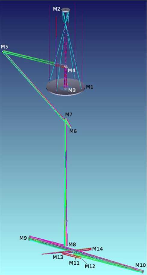
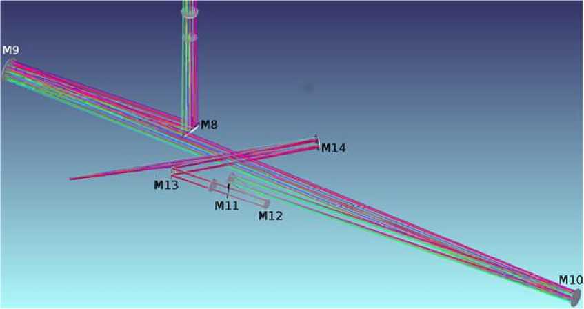
Figure 1. An optical coude layout of LST-3 with a focal length of 80 m: general view (top), detailed view of M9, M10, and M14 mirrors (bottom)
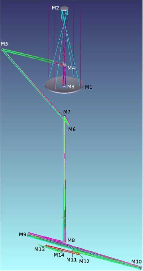
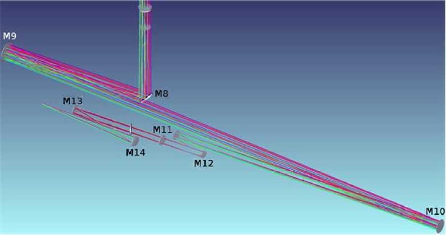
Figure 2. An optical coude layout of LST-3 with a focal length of 40 m: general view (top), detailed view of the M9, M10 mirrors (bottom)
Coude focus
Focal length of 80 m
The general view of the system is shown in Figure 1, and design parameters are listed in Table 1. The focal length is formed by the off-axis parabolic mirror M14, installed in a parallel beam after the collimation mirror M9, building a pupil on the deformable mirror of the adaptive optical system (AOS) consisting of the collimation mirror M9, tip/tilt mirror M11, and deformable mirror M12. Segment displacement from the parabola axis is 342 mm with an optical diameter of 250 mm. This provides a convenient location for the focal plane and a telecentric path of rays handy for aligning optical systems of equipment.
The tunable system consisting of a single smallaperture off-axis parabolic mirror together with a two-mirror AOS ensures the diffraction image quality; the energy density is >80 % in the visible range, up to 0.38 µm in a circle 0.1 arcsec in diameter (38.8 µm) with due regard to the influence of central screening. In instruments of such a complexity as LST-3, the main contribution to energy density decrease is usually made by factors such as surface shape instability, atmospheric wavefront deformations, and effect of air temperature inhomogeneities in long optical paths. All these factors are compensated by methods of active and adaptive optics, which, being installed near working focal planes, also corrects wavefront deformations of the calculated optical system.
Focal length of 40 m
The general view of the system is shown in Figure 2, and design parameters are listed in Table 2. The optical system with a focal length of 40 m is placed on the coude platform after the collimation mirror M9 and AOS units. The camera part is an outside focal two-mirror system in which the M9 and M10 mirrors represent a Brachi-type decentrical Gregory system with a large parameter of secondary mirror position. This provides a telecentric path of rays required for scientific equipment.
The M13 and M14 mirrors are ellipsoidal segments with off-axis displacements of 152 and 178.5 mm respectively and identical optical diameters of 220 m. For such a high-aperture system as LST-3, the 40 m focal length even for the working field 2ω=2´ should be assigned to small (1:13.3 aperture ratio). For such a system it is not a trivial task to achieve a higher quality of aberration correction. Nevertheless, the two-mirror reverse system has allowed us to achieve a diffraction quality, at least within half the field of view. The meanfield energy density in a circle 0.1 arcsec in diameter (19.4 µm) is >75 % as in the layout with a focal length of 80 m, up to the blue boundary of the visible range. As in the case with the 80 m focal length, all comments about the contribution of the factors, unrelated to errors in both calculation and manufacture of complex off-axis optical surfaces, which are inevitable for the system with the 40 m focal length, to image concentration are true.
Table 1
Parameters of the optical coude layout, 80 m focal length
|
No. of surface |
Designation in Figure 1 |
Radius of curvature, mm |
Distance, mm 1 |
Conic constant (–e2) |
|
1 |
M1 |
–11300 |
–6800 |
–1 |
|
2 |
M2 |
1847.9 |
6800 |
–0.368 |
|
3 |
M3 |
–3800 |
–31062.2 |
–0.669 |
|
4 |
M9 (AOS collimator) |
–22191.9 |
22521.8 |
0 |
|
5 |
M14 ( f =80 м) |
–8093.8 |
–4021.8 |
–1 |
1Distances without regard to positions of flat breaking mirrors
Table 2
Parameters of the optical coude layout, 40 m focal length
|
No. of surface |
Designation in Figure 5 |
Radius of curvature, mm |
Distance, mm1 |
Conic constant (–e2) |
|
1 |
M1 |
–11300 |
–6800 |
–1 |
|
2 |
M2 |
1847.9 |
6800 |
–0.368 |
|
3 |
M3 |
–3800 |
–31062.2 |
–0.669 |
|
4 |
M9 (AOS collimator) |
–22191.9 |
21429.3 |
0 |
|
5 |
M13 |
–1530.6 |
–1663.7 |
–0.838 |
|
6 |
M14 |
1303.6 |
2375 |
–0.256 |
1Distances without regard to positions of flat breaking mirrors
Table 3
Parameters of the Nasmyth optical layout, 20 m focal length
|
No. of surface |
Designation in Figure 5 |
Radius of curvature, mm |
Distance, mm1 |
Conic constant (–e2) |
|
1 |
M1 |
–11300 |
–6800 |
–1 |
|
2 |
M2 |
1847.8 |
6800 |
–0.368 |
|
3 |
M3 |
–3800 |
–5650 |
–0.669 |
|
4 |
M5 |
–773.4 |
702.4 |
–1.05 |
|
5 |
M6 |
505.7 |
–1020.4 |
–0.334 |
1Distances without regard to positions of flat breaking mirrors
Nasmyth focus
Focal length of 20 m
The general view of the system is shown in Figure 3, and design parameters are listed in Table 3. In this case, the M5 and M6 mirrors feature the Brachi-type decen-trical Gregory system with inner focal plane position. This provides a telecentric path of rays required for scientific equipment.
The 20 m focal length is, in our opinion, close to that critical for the two-mirror relay system in the field 2ω=2´. For the telecentricity condition to be fulfilled, a minimum increase is required in the last power mirror M6, which is an ellipsoidal segment displaced by 111 mm from the axis and having a 210 mm optical diameter, with maximum asphericity reaching 214 µm. The M5 mirror is a hyperboloid segment with 136 mm displacement, 280 mm optical diameter, and 510 µm maximum asphericity. At present, however, technologies of polishing and control of such surfaces are successfully
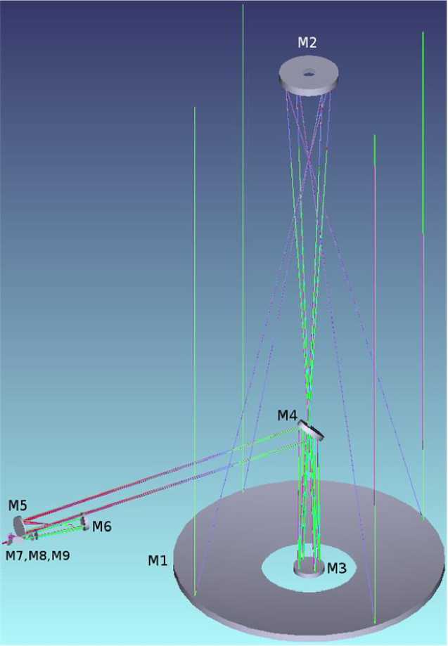
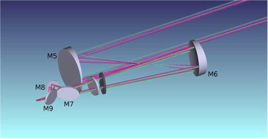
Figure 3. An optical Nasmyth layout with a focal length of 20 m: general view (top), M5, M6 mirrors (bottom)
adopted in a number of companies of the world and Russia. The surfaces are controlled using simple and inexpensive holographic correctors and are polished on machines with software-controlled motion of the tool. Nowadays, surfaces with a gradient of asphericity that is by an order of magnitude greater are successfully manufactured for space and military applications.
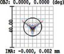
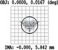
Figure 4 shows that even with the two-mirror relay system the diffraction quality of aberration correction in the desired working field of view is available. Except for minor distortion (<0.4 %), the energy density for central screening in the 0.1 arcsec circle throughout the field is 75 % too, at least in the red region. Besides the previously mentioned influence of factors on the image quality for channels with the 80 and 40 m focal lengths, unrelated to the calculation and manufacture of the optical system, the problem of the aberration correction quality becomes important in a channel with such a large aperture ratio (1:6.67). The layout with the 20 m focal length will include two main working instruments: a small-field filtrograph based on tunable Fabry—Perot interferometers and an echelle spectrograph intended for the coronagraph with the 5 arcmin field of view.
Coronagraph mode
In the coronagraph mode, the ray path for which is shown in Figure 5, to eliminate the scattering light from the supports on which the secondary mirror M2 is mounted and from the unit of this mirror, it is intended to use a special stop 700 mm in diameter, which transmits light only to one of the segments of the main mirror, displaced from the optical axis by 1100 mm (Figure 6). Light from the Sun and corona falls on the stop through a hole of corresponding size in the dome. In this mode, the telescope will be pointed at a region outside the solar limb for a distance of ~1.3 R from the disk center so as the field of view covers regions of the inner corona for distances of (0.1÷0.3) R from the limb. Filtergrams and spectrograms in the Nasmyth focus will be obtained in coronal emission lines in a wavelength range 0.4–1.5 µm. In the focus of the main mirror, instead of the heat stop we set a unit comprising a cooled artificial moon as a reflecting mirror and a Lyot stop. The secondary mirror in this case builds an image of the entrance pupil, in which the Lyot stop is installed, near the focal plane. Very high requirements are imposed for the design of elements in the primary focus and for the quality of the surface of the main mirror coronograph segment.
A decrease in the focal ratio in the coronagraph mode to 1:28.6 makes the image quality diffractionlimited across the entire field of view 2ω=5 arcmin. As noted in the previous section, since in the coronograph mode the main instrument will be the echelle spectrograph with diffraction dispersion units designed for a range from the 0.53 µm green coronal line to the 1.5 µm magnetosensitive lines of the near IR range, an important factor is the image quality in the spectrograph camera system.
BASIC INFORMATION ON THE PLANNED SCIENTIFIC EQUIPMENT
It is obvious that the overarching objective is to provide such a unique instrument as LST-3 with state-of-the-art scientific equipment. Only with combination of high optical characteristics of the telescope and parameters of spectral and filter equipment, as well as photodetectors we can obtain interesting scientific results. The practice of modern solar instrument engineering shows that there is a need for at least the following equipment: compact spectrograph and filtrographs of different applications in the Nasmyth focus; full-field diffraction spectrograph and compact spectrograph-spectropolarimeter in the coude focus on a rotating platform compensating for image rotation. On the same platform is a filtrograph based on Fabry—Perot interferometers and a wide-band filtrograph. In addition, auxiliary telescope guides can be used for pointing the main telescope. All scientific equipment and the telescope itself are controlled by a unified automated control system (ACS).
Compact spectrograph in the Nasmyth focus
The spectrograph is designed for solar observations; and in the nighttime, other astrophysical objects. To minimize polarization and other effects, it is placed on the Nasmyth platform. A distinctive feature of this instrument is a larger angular aperture as compared to other scientific instruments of LST-3. It is assumed to be used mainly for Stokesmetric measurements of solar magnetic fields. The instrument should be capable of rapidly adjusting to observations in different spectral lines in a wide wavelength range. Such an instrument is an off-axis autocollimation Littrow spectrograph. The slit height should be at least of the size of the solar area image produced by the telescope objective and relay optics of the Nasmyth platform. The spectrum is projected on a matrix photodetector of 1024×512 or more pixels (the pixel size is 16×16 µm). Photodetector parameters can be specified at the stage of design and construction of the spectrograph. Its spectral resolution is not less than 0.02 Å in the spectrum range 500–900 nm and not less than 0.1 Å in the rest of the region. To scan the spectrum, the diffraction grating is intended to be rotated at calculated angles by the mechanism of rapid transition to spectral regions and fine adjustment to certain spectral lines. Because of small light fluxes, for star observations the diffraction grating can be changed to the other (perhaps holographic) operating at lower diffraction angles and providing a dispersion of ~1 Å/mm. Before the entrance slit of the spectrograph, we should install an optical unit to place removable interference light filters. The parallel path of rays incident on the diffraction grating is made by moving the autocollimation mirror. The spectrum image can be focused by shifting the photodetector unit. The main working lines are 5250, 6302, 8540, 10830 Ǻ. The spectrograph should ensure simultaneous recording of Stokes profiles in several spectral lines near the aforementioned lines in the wavelength range of the order of 10 Å.
Fraction of Enclosed Energy
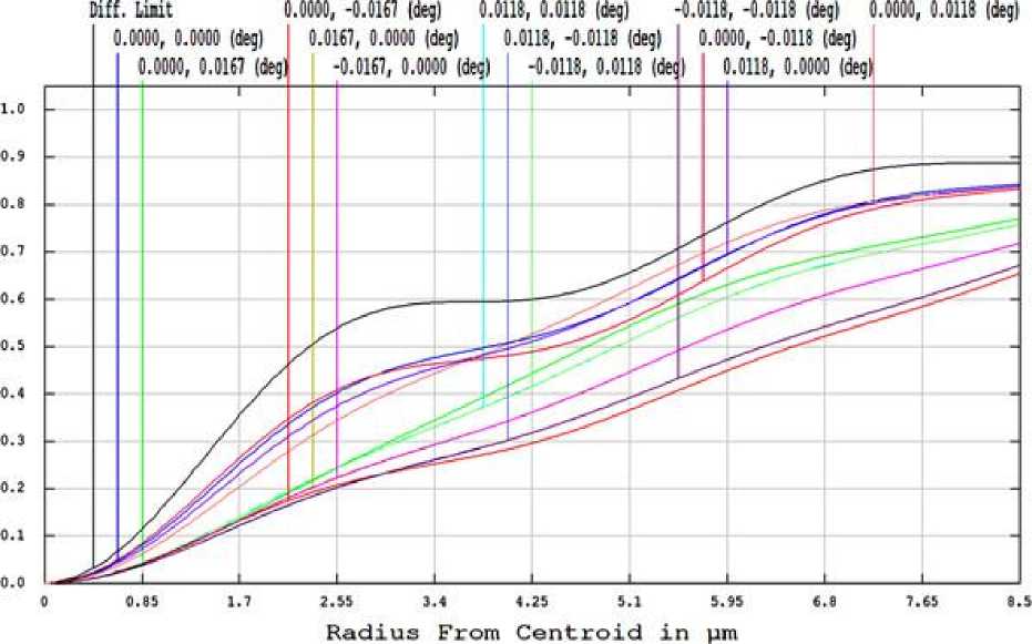
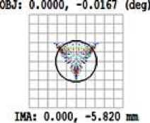
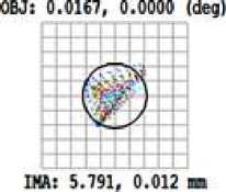
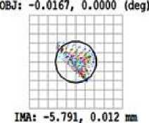
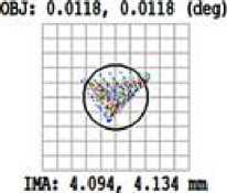
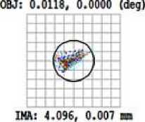
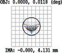
Figure 4. Geometric aberrations (top) and encircled energy concentration for the LST-3 optical layout with a focal length of 20 m in the Nasmyth focal plane
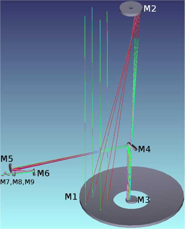
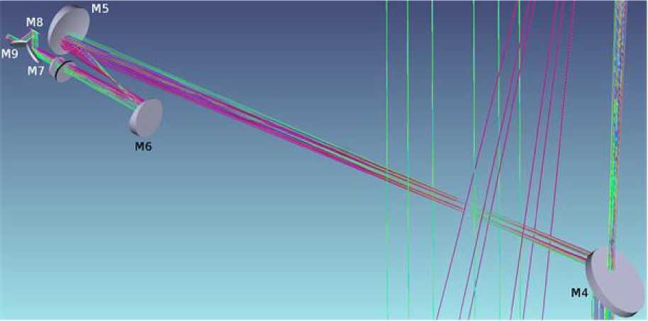
Figure 5. Optical layout of LST-3 in the coronograph mode
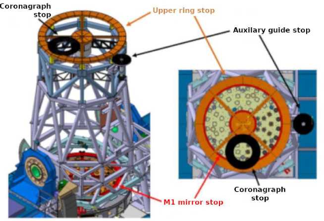
Figure 6. Preliminary view of LST-3 in normal (left) and coronograph (left) modes
The focal length of the off-axis autocollimation mirror is 1.7–2.3 m. Parameters of the diffraction grating in the solar observation mode: the number of lines/mm ( N ) × order ( K ) is minimum 3000; diffraction angles should be in the range from 40° to 60°; the size of the shaded area is at least 200×300 mm. Parameters of the diffraction grating for star observations will be refined in the future.
The spectrograph is designed as a separate complete module whose housing is composed of a block of diffraction grating, tube, collimation mirror in frame. The overall optical spectrograph layout conforms with the LST-3 layout. The spectrograph is equipped with a slitjaw imaging system to control image focusing and coordinates of the observable solar region.
Diffraction spectrograph with integral field unit in the coude focus
This instrument is one of the main LST-3 instruments. It differs from the classical one-slit spectrograph in the fact that it can be used for simultaneous observations of two-dimensional field of view, transformed with an Integral Field Unit (IFU) into a set of long slits, which are then recorded by one photodetector or a mosaic of CCD matrices. As a basis for the image slicer we can utilize the MuSICa device for the EST spectrograph with the difference that the polarization analysis in our case is carried out before the M3 mirror. In this case, we can transform the spectrograph into the common one-slit spectrograph with a long slit comparable to the field of the telescope.
To observe different layers of the solar atmosphere, the spectrograph simultaneously records emission in different spectral lines. In this case, we use three channels; each of them can simultaneously record at least two spectral lines of different orders of the diffraction grating with two cameras. Each of the channels is optimized for operation in its wavelength range and comprises a separate dispersion unit.
The primary objective of LST-3 — to obtain spectrograms with a maximum spatial resolution of 0.1″ — can be achieved in a sufficiently small field of view of ~6×12 arcsec. It is, however, desirable to have several operating modes with different field of view and resolution, therefore together with the high spatial resolution (6″×12″ field of view, ~0.1″ resolution) a mode is provided with moderate spatial resolution of ~0.3″(~18×36 arcsec field of view) and a mode with a larger field of view of 42×84 arcsec but with low spatial resolution. The modes should be changed without noticeable decrease in spectral resolution.
The spectrograph is assumed to be equipped with an autonomous scanning system, which can sequentially record all areas of the field of the telescope. Mechanics should provide such a scanning speed at which at a maximum resolution the entire field of the telescope can be scanned for no less than 50 s.
Requirements for spatial and spectral resolution, as well as for the field of view defines the requirements for the photodetector. The photodetector pixel is assumed to have a square shape. The pixel size for the photodetector of the visible range is 10 µm; for the photodetector of the IR range, 20 µm. A detector is likely to be required with the number of pixels of 4K×4K or more. Reading frequency determined by parameters of operation of the polarization analyzer should be at least 30 Hz.
Compact spectrograph with echelle grating
This spectrograph like the previous one is set in the coude focus, but is based on the autocollimation layout and has a minimum number of optical elements. The spectrograph is mounted on an optical table-bench. It is designed mainly for real-time spectropolarimetric solar observations with high spatial and temporal resolution. The field of view of the instrument should cover a considerable part of the field of the telescope — of order of 84″–120″ at 0.1″ resolution (0.025″ per 1 pixel of the photodetector). The slit width may vary to 1″. The field of view in wavelength depends on the model of photodetector and must be at least 15-20 A. The scanning system moves the bench with the spectrograph with a mechanical accuracy of at least 0.025″ (scanning accuracy in fact should be determined by image quality). The instrument is equipped with a video system of image acquisition from the slit at different wavelengths in a wide spectral range. This video system should provide the same characteristics of spatial and temporal resolution as the spectrograph provides. This will allow us to determine the position of the slit on the solar disk at different wavelengths. For this purpose, we suggest using a wide-band filtrograph (WBF).
Wide-band filtrograph
The wide-band filtrograph (WBF), put in the coude focus on the rotating platform, is designed for taking solar surface images with high spatial and temporal resolution in several wavelengths. It will be used for studying dynamics of phenomena associated with magnetic elements in the solar atmosphere, chromospheric dynamics, structural elements of sunspots, and fast flare processes. Another purpose of WBF is to open up the possibility of mathematical image reconstruction, which should help to overcome the quality limit imposed by LST-3 AOS. To do this, WBF should receive a series of images with the maximum cadence (short exposures), which is possible when working in a relatively wide bandpass.
WBF is a two-channel device, where each channel comprises a set of monochromatic interference filters (IF) for blue and red spectral ranges. The following lines are proposed as working spectral lines: in the blue channel — K CaII (3933 Å), G band (4305 Å), continuum in the blue region (4320 Å), Hβ (4861 Å), continuum in the green region (5550 Å); in the red channel — continuum in the red region (6540 Å), Hα (6563 Å), TiO 7058 Å, HeI 10830 Å. The division into channels is provided by light reflection or transmission through the beam splitter, as well as by using the light reflected from the entrance slit of spectral instruments. Two spectral channels of WBF operate either simultaneously or alternatively depending on the spectral region selected for studying with WBF and spectral instruments when they work with WBF. WBF is equipped with systems of automatic change of interference filters, image capture with software for processing images post facto. Software and hardware must provide data processing in real time on the assumption that an observer receives a result not later than within 10 s after obtaining an image in each of the channels. The result is used to correct the observation program in other LST-3 instruments.
Each of the channels can obtain a solar image in at least four wavelengths alternately. To work with WBF, we have to use the quickly tip-tilt mirror and LST-3 AOS to compensate for atmospheric turbulence. The filtrograph is mounted on an optical table-bench with independent fixing of all optical elements. Each channel provides a series of images with short exposure for 5–15 s, depending on the operating mode. Filter change in the turret and corresponding adjustments should be done for no more than 350 ms (the goal is 250 ms). The total time of data acquisition and processing and presentation of results to a user must be no more than 10 s in each channel. Data acquisition for one wavelength without processing is ~1 s.
The instrument has a field of view of 2 arcmin at a resolution corresponding to the diffraction limited resolution of the telescope optics. To ensure the required field of view, optical filters must have the maximum possible diameter of no less than 62 mm (clear aperture). Interference filters in both the channels must be installed in telecentric rays or in a parallel beam near the pupil image. The system can be focused automatically by shifting one of the relay objectives with the aid of a correlation tracker of the additional camera in a relatively small part of the image from the beam splitter. To maximize the coverage of the field of view requires an up-to-date scientific CCD or CMOS camera (30 frames/s or more) with a frame size of not less than 4K×4K pixels.
The camera can scan in the focal plane if due to the small size of the photodetector the field of view is restricted. Image pieces can be stitched in software. In this case, we should specify requirements for the system response speed. Speckle-interferometry methods require a series of images of at least 80 frames captured with a short exposure.
Narrowband filtrograph based on Fabry— Perot Interferometers
A narrowband filtrograph (NDF) is set in the coude focus and is designed for taking images of the solar disk in several wavelengths of a narrow spectral range to study fine elements of the photosphere and chromosphere. This instrument will provide two-dimensional maps of Doppler velocity, magnetic field (Stokes polarimetry), and radiation intensity; it can monitor transverse motions with a resolution of ~75 km or higher at the field of view of at least 1×1 arcmin.
The instrument consists of two channels and can simultaneously observe two spectral lines, e.g. photospheric and chromospheric. Each channel can be adjusted to another spectral line for quasi-simultaneous observations in 4–6 lines. Each channel can be optimized to work in the green and red spectral ranges and has three large-aperture Fabry—Perot interferometers to achieve maximum performance characteristics.
The NBF spectral range is 390–1600 nm (the latter value can be specified in the future), the spectral resolution is 180000–300000 depending on the spectral range and operating modes. The ghost intensity is lower than 0.01 %, the stability in wavelength is greater than 0.1 mÅ per 1 hr. The field of the instrument is at least 1 ' ×1 ' at maximum spatial and spectral resolution. The purpose is to achieve a field of view of 1.5 ' ×1.5 ' and more. Spatial resolution is ~0.05 '' –0.1 '' (0.025 '' and 0.05 '' per 1 pixel, the goal is per 2 pixels) and depends on the mode to achieve a compromise between the field of view, spatial and spectral resolution.
The instrument will use Fabry—Perot interferometers with ~150–200 mm aperture. They are installed in the telecentric beam in the image plane to eliminate bandpass variations across the field of view. To isolate a desired band, we use as small number of additional filters as possible. The latter should have a relatively wide bandpass of >0.7 nm. The system should provide the maximum light transmission (~50 %).
For joint observations with WBF as well as for problems of speckle reconstruction of images, NBF has a channel with wide-band filters operating with the same temporal and spatial characteristics as the main channels.
BRIEF OVERVIEW OF AUTOMATED CONTROL SYSTEM
Software of ACS is designed to control hardware of the telescope, perform scientific experiments, obtain and process data. The system consists of the following basic systems: TCS (control of mechanics and systems of the telescope, as well as scientific instruments), DAHS (control of digital video cameras, lines for data processing and reduction), OCS (high-level control of the entire system of the observatory). The ACS software represents the structure of controlled hardware units with the use of an object-oriented approach. Since LST-3 is created as an instrument with a service life of 30 to 50 years, it should be constantly modernized to meet up-to-date requirements of experimental problems in solar physics. ACS must, therefore, provide support for new executive devices, new operation algorithms of subsystems and the system as a whole. The purpose is to solve these problems in one software platform for at least 25 years.
The control algorithms are combined into groups to avoid software code duplication. To do this, we use principles of object-oriented programming and division of software into relatively independent software units, into server and client sides. As a basic operating system we plan to use SUSE Linux OpenSUSE, and, if necessary, commercial versions of SLES/SLED; the use of other systems is minimized. In a number of terminal devices, to interact with users we can apply Google Android, Microsoft Windows, etc.; in the data acquisition system, we can partially apply Microsoft Windows.
The system uses special devises — hardware controllers (hereinafter simply controllers) to drive engines, sensors to ensure high- and low-level algorithms. We must explicitly assign interfaces to control devices and/or subsystems. This is especially true when the controller ensures the operation of not one executive devices, but a group of executive devices.
It is important to emphasize that in the development of LST-3 ACS we will use the wide experience in development of ACSs of ISTP SB RAS solar telescopes.
BRIEF INFORMATION ON THE ENGINEERING AND TECHNICAL SUPPORT BUILDING OF LST-3
The overall architectural appearance of the developed LST-3 complex is shown in Figure 7. The complex consists of four main blocks. The first block is a tower for the telescope and dome. The second block includes engineering equipment necessary for operation of the telescope and dome, as well as a service lift to transport the unit of the main mirror and other major units of the telescope. The third block is technical with an assembly shop with rooms for a unit of application of reflecting coatings, a studio, and a tool room. The fourth block is laboratory and administrative. It contains equipment for adjusting optomechanical units, clean room with an optical bench, laboratory for development and maintenance of electronics. There are also rooms for staff accommodation in this block. The heat generated by all systems and equipment is removed through air shafts on the north side of the building.
CONCLUSION
The presented versions of optical layouts may be basic for the development of solutions satisfying initial geometric parameters of the three-mirror system with the small-diameter mirror M2 and 1:2 relative ratio of M1. Off-axis mirrors of the reverse system are produced by Russian and foreign manufacturers using well-proven technologies. The aberration correction quality in the working field of view is diffractive and admits the possibility of simplifying the optical layout,
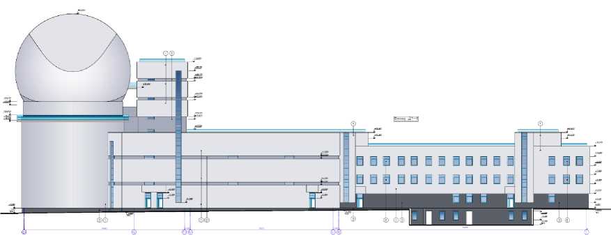
Figure 7. General view of LST-3 buildings. From left to right: tower, tower building, technical block, laboratory and administrative block
in particular replacing the M3 mirror by the parabolic one for all versions considered. Its replacement is, however, not required when passing to different focal lengths, which simplifies the operation process. Moreover, the version is admissible, in our opinion, which involves utilizing three-mirror reverse systems with replacing the M3 mirror by a spherical one as secondary. In this case, the system may be anastigmatic, and the maintainance of telecenticity due to the introduction of additional power surface may be combined with the capability of changing the focal length of the system within certain limits.
It should be noted that in this paper we present only the main characteristics of the new telescope; detailed development of working documentation is a long-term challenge. The main part of design works will most probably be performed by the well-known Belgian firm AMOS (Advanced Mechanical and Optical Systems), which has extensive experience in developing and constructing large astronomical telescopes, including solar telescopes. AMOS engineers have already participated in the development of the draft design of LST-3.
The work was performed with budgetary funding of Basic Research program II.16.
Список литературы Проект крупного солнечного телескопа с диаметром зеркала 3 м
- Григорьев В.М., Папушев П.Г., Скоморовский В.И., Чупраков С.А. Трехметровый солнечный телескоп-коронограф необходим солнечным физикам России // Всероссийская астрономическая конференция: Тезисы. Санкт-Петербург, 6-12 августа 2001 г. 2001. С. 53.
- Grigor'ev V., Pimenov Y., Papushev P., et al. Proposal Large Solar Telescope in Russia // 26th Meeting of the IAU. Special Session "Astronomical Facilities of the Next Decade" Czech Republic, Prague, 16-17 August, 2006. 2006. SPS1, id 19.
- Liu Z., Deng Y., Ji H. The Chinese Giant Solar Telescope // Proc. the International Astronomical Union. 2013. V. 8 (S300). P. 349-354. DOI: 10.1017/S1743921313011186
- McMullina J.P., Rimmelea T.R., Keila S.L., et al. The Advanced Technology Solar Telescope: Design and Early Construction // Proc. SPIE. 2013. V. 8444, N. 7. P. 1-12.
- Rimmele T.R., Wagner J., Keil S., et al. The Advanced Technology Solar Telescope: beginning construction of the world's largest solar telescope // Proc. SPIE. 2010. V. 7733. P. 1-12.
- Sánchez-Capuchino J., Collados M., Soltau D., et al. Current concept for the 4m European Solar Telescope (EST) optical design // Proc. SPIE. 2010. V. 7733, N. 36. P. 1-8.
