Professional Courses for Computer Engineering Education

Author: Yinan Kong, Yimin Xie
Journal: International Journal of Modern Education and Computer Science (IJMECS) @ijmecs
Article in issue: 1 vol.2, 2010.
Free access
A sequence of professional courses of study in Computer Engineering at the authors’ university was initiated. These included Digital Fundamentals, Programmable Logic Design, Computer Hardware and Digital Systems Design. This paper presents a study on how the problem based learning has been used for these courses. It also describes how CDIO (Conceive, Design, Implement, Operate) concepts have been applied with an overview of all the hardware resources necessary to support the degree.
Computer Engineering, Engineering Education, Problem Based Learning, CDIO, Digital Systems
Short address: https://sciup.org/15010040
IDR: 15010040
Text of the scientific article Professional Courses for Computer Engineering Education
Published Online November 2010 in MECS
The Problem Based Learning (PBL) approach has been used in the development of a sequence of professional courses for the degree of Computer Engineering at the authors’ university [1]. Team-based projects form major components of these courses. All the projects follow the CDIO (Conceive, Design, Implement, Operate) context of engineering education that is being adopted by considerable computer and engineering departments world-wide.
-
A. CDIO Concepts
Engineering education has evolved into the teaching of engineering science where teaching engineering practice was increasingly de-emphasized. Industry in recent years has found that graduating students, while technically adept, lack many abilities required in real-world engineering situations. Hence, major companies created lists of abilities they wanted their engineers to possess (e.g. Boeing's Desired Attributes of an Engineer).
A CDIO (conceive-design-implement-operate) program [2] is based on the principle that product and system lifecycle development and deployment are the appropriate context for engineering education. The CDIO concepts, which basically are a model of the entire product cycle, form a worldwide initiative in Engineering Education. CDIO is considered the context for engineering education in that it is the cultural framework, or environment, in which technical knowledge and other skills are taught, practiced and learned.
-
B. The Computer Engineering Degree
There are several basic courses that are common to all the Engineering degrees at the Department of Electronic Engineering at the authors’ university. Apart from them, there are four specialized professinal courses compulsory for the Computer Engineering Degree: Digital Fundamentals (in the first year), Programmable Logic Design (in the second year) and Computer Hardware and Digital Systems Design (in the third year). The scope of the topics covered in the four courses is represented by the content of the textbooks and references shown below in Table I.
II. Digital Fundamentals
Digital Fundamentals is the fundamental course for Computer Engineering as well as a few other Engineering degrees. Enrolments have been over 150 since 2008.
TABLE I.
Author(s) of Text/Reference Books
|
Course |
Author |
Text/Reference Book |
|
Digital Fundamentals |
T. Floyd |
Text [3] |
|
Digital Fundamentals |
R. J. Tocci, N. S. Widmer and G. L. Moss |
Reference [4] |
|
Programmable Logic Design |
T. Floyd |
Reference [5] |
|
Computer Hardware |
P. Spasov |
Text [6] |
|
Computer Hardware |
R. J. Dirkman and J. Leonard |
Reference [7] |
|
Digital Systems Design |
C. H. Roth and L. K. John |
Text [8] |
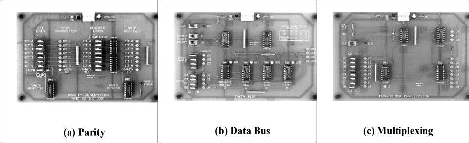
Figure 1. Concept-specific hardware trainers for Digital Fundamentals
To foster the Problem Based Learning component, a set of hardware, concept-specific trainers, is developed for the eleven practical sessions throughout the course and it also needs to be used for demonstrations in class. The requirements for these trainers are the hardware has to be easy to setup, and also that the printed-circuit board (PCB) must be fully operational after the connection of the power supply (and clock). It must not require any additional wiring (or, in some cases, a minimum amount of wiring) from the first-year undergraduates and all the relevant signals must be labeled and monitored by lightemitting diodes (LEDs).
For this reason, a typical trainer of this type was designed to include small interactive PCBs that focus on digital concepts of parity, multiplexing, adder/accumulators, flip-flops/counters, data bus and shift registers. Then the advantage is realized in that the PCB is exercised by setting switches or pressing pushbuttons (to provide a single clock pulse), and by monitoring signals using the LEDs or a logic analyzer. This exactly satisfies the requirement of a simple class demo and also achieves the aim of spurring the interest of new undergraduates in digital systems design. Fig. 1 shows three of these PCBs.
III. Programmable Logic Design
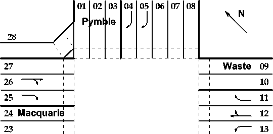
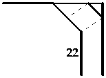
For the inaugural delivery of Programmable Logic Design in 2007, a PBL approach was used where student teams were required to develop a digital controller on an FPGA to control the traffic flow of a complex traffic intersection. The problem is an identifiable, real-world problem, and there is a huge scope for ingenuity in each of the conceive, design, implement and operate stages of the problem solution. A diagram of the traffic intersection is shown in Fig. 2.
At this intersection, there are ten sets of red, amber and green lights for vehicular traffic, and all of the 16 lanes for traffic approaching the intersection could be installed with traffic sensors. There are other lights and sensors for pedestrian traffic. This is an 8-week project where students worked 3-4 hours each week on it in groups of 4.
г г Ryde

Figure 2. The traffic intersection for the project in Programmable Logic Design
A. Hardware Resources for Project Based Learning
Programmable Logic Devices (PLDs) such as the Xilinx range of Field Programmable Gate Arrays (FPGAs) [9] provide educators with a huge scope for the definition of design and build projects in the field of digital systems. There are many examples of these projects which include a traffic-light controller, arithmetic logic units (ALUs) for computers, floating-point arithmetic units, frequency meters, boundary-scan testers and simple computers.
A PCB with LEDs in positions corresponding to those in the physical intersection was prepared to facilitate testing. This is shown in Fig. 3(a). To support those teams who may opt for VHDL implementation [10], a new PCB containing a FPGA and a microcontroller, together with a model of the intersection, has been developed. This is shown in Fig. 3(b). To facilitate the development of a prototype, a PCB with a static RAM and tri-state buffers has been built. This is shown in Fig. 3(c). The hardware resources for PBL have helped students gain the skills necessary to develop complex digital systems.
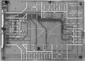
(a) Traffic Intersection
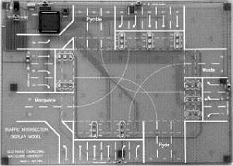
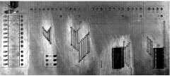
Figure 3. PBL hardware modules in Programmable Logic Design.
-
B. CDIO Stages for a Traffic-Light Controller
The documentation of the project identifies about thirty problems classified under the conceive, design, implement and operating issues of the project. Examples of the problems of each of the conceive, design, implement and operate issues are listed in Table II.
TABLE II.
Examples of CDIO Issues for a Traffic Light Controller in Programmable Logic Design
|
CDIO Stage |
Problem Area |
|
Conceive |
Inputs and Outputs for Digital Control |
|
Conceive |
Simplification of Controller Specifications for preliminary development in order to establish the design procedure before the final design is initiated |
|
Conceive |
Control Algorithms |
|
Design |
Hierarchical Design |
|
Design |
FSM (Finite State Machine) State Coding |
|
Design |
One-Hot Encoding |
|
Design |
Synchronous Delay Circuit |
|
Design |
Design for Testability |
|
Implement |
FPGA |
|
Implement |
VHDL |
|
Operate |
Testing |
|
Operate |
Real-time Operation |
In the first Conceive stage, the customer needs are defined and the technology to be used is determined from the technology taught in this course: Field Programmable Gate Arrays (FPGAs). The detailed specification of the controller is considered a “conceive” issue, and the documentation points out that optimization of the controller design may be achieved at the initial systems-specification stage of the project.
The design stage of the project is, by far, the most difficult, and about 20 issues are documented. The issues of “hierarchical design”, “one-hot encoding” and “synchronous delay circuit” were central to an effective approach to design. After a period of about two weeks into the seven-week period for the project, the teams were alerted to this possibility. In 2010, most of the teams took this “hint”, and were able to complete the project on time.
Take the issue of hierarchical design as an example. Six traffic flows of the intersection are usually identified at the top hierarchical level of design as shown in Fig. 4. Each flow has its own operating features which turn out to be the second level of design, and each operation has its own combination of states of traffic lights to be designed at the bottom level.
Further details of each of the 30 issues are given in the student documentation. A standard tabular form is used. References to text/reference books are sometimes given. An example is given in Table III.
In the implement stage, the hardware implementation tools using FPGA technology are illustrated in Fig. 5.
The operate stage also uses the hardware models of the intersection shown in Fig. 5.
-
C. Documentation
A standard format (in an A4-size sheet) has been used for the documentation of each issue. This documentation is included in the notes that are available at the beginning of the semester before the start of the team project. The documentation gives students some background or insight to the CDIO issues and suggests meaningful activities. [11] Table II and Table III are both typical examples of the documentation.
IV. Computer Hardware
Computer Hardware is a third-year course teaching the principle and applications of microcontrollers. A special microcontroller trainer was developed for this course. Microcontroller trainers have hardware and software resources that give students the experience of exercising and developing microcontroller-based systems. Microcontroller interfacing is important and experiments should cover parallel ports, serial ports, interrupts, timing and digital/analogue inputs/outputs. As bit-level manipulation is required, especially for a memorymapped input/output architecture (such as that of the Motorola 68HC11 microcontroller), some experience with assembler coding is required. The microcontroller trainer consists of a microcontroller development board interfaced to a desktop computer and a specially designed input-output PCB. This supports a number of experiments on computer interfacing. The 68HC11 Evaluation Board and the Input/Output Board are shown in Fig. 6.
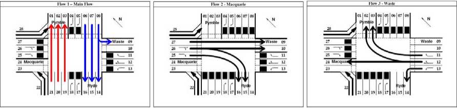
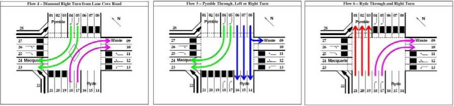
Figure 4. Six traffic flows at the top level design of the traffic intersection in Programmable Logic Design
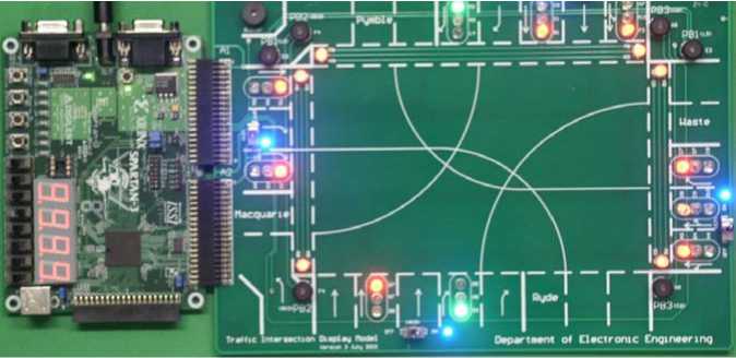
Figure 5. The FPGA implementation of the traffic controller in Programmable Logic Design
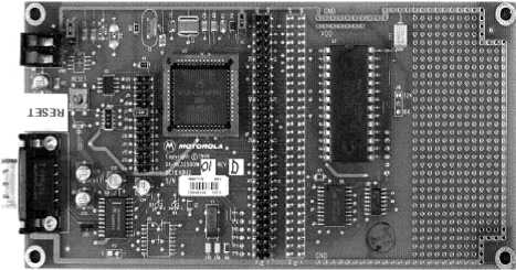
(a) 68HC11 Evaluation Board
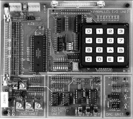
(b) Input/Output Board
Figure 6. The Microcontroller Hardware Trainer
V. Digital Systems Design
The team project in Digital Systems Design is to design a bus-structured computer, which resembles the microcontroller investigated in the prerequisite course, and computer hardware. This arrangement of the curricula allows students in Digital Systems Design, who have studied microcontroller and its applications in computer hardware, to be able to develop a similar chip with the capabilities they have learned to use. This course had its inaugural delivery in Semester 2, 2009.
-
A. Project Details
The project was based on programmable logic devices (GALs or FPGA). The final documentation also identified conceive, design, implement and operate issues of the project. A block diagram of the computer is given in Figure 7.
The computer is modelled on the architecture of the 68HC11 microcontroller [5]. Operands are represented to only 4-bit accuracy and memory size is only 256 words. The instruction set contains only 16 instructions, and two condition codes and several addressing modes are implemented.
table iii. Example of the Documentation of a CDIO Issue for the Project in Programmable Logic
Design
|
Conceive Problem Area |
Inputs and Outputs for Digital Control |
||||||||
|
Problem |
The traffic-light controller is a digital controller with digital inputs and digital outputs. Firstly, it is necessary to identify all digital inputs and all digital outputs, and then to determine the number of inputs and outputs. The main problem is the specification of the relationship between the inputs and outputs. |
||||||||
|
Proposed solution |
The outputs are the traffic lights for all roads that enter the intersection. These include traffic lights for vehicular traffic travelling through the intersection or turning either left or right. The traffic lights should be determined so that traffic flow through the intersection is optimised. |
||||||||
|
References |
|||||||||
|
Solution/ notes |
(In the following tables, A, B, C and D represent the traffic entering the intersection from Pymble, Waste, Ryde and Macquarie.) Number of inputs (traffic sensors) |
||||||||
|
One sensor for lanes in same direction |
One sensor for A left and A through |
One sensor for B left, through or right |
One sensor for D through or right |
No sensor for A through or C through (default) |
Number |
||||
|
N |
N |
N |
N |
N |
16 |
||||
|
Y |
N |
N |
N |
N |
11 |
||||
|
Y |
Y |
N |
N |
N |
10 |
||||
|
Y |
Y |
Y |
N |
N |
8 |
||||
|
Y |
Y |
Y |
Y |
N |
6 |
||||
|
Y |
Y |
Y |
Y |
Y |
4 |
||||
|
List inputs Number of outputs (traffic lights) |
|||||||||
|
Combine A through with A left |
Combine B through with B left and B right |
Combine D through with D right |
Number |
||||||
|
N |
N |
N |
30 |
||||||
|
Y |
N |
N |
27 |
||||||
|
Y |
Y |
N |
21 |
||||||
|
Y |
Y |
Y |
18 |
||||||
|
List outputs |
|||||||||
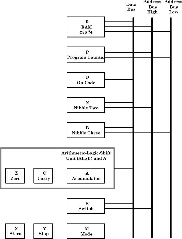
Figure 7. Block diagram of the bus-structured computer in Digital Systems Design.
While the documentation of the project describes a simplistic computer, expansion of the computer’s functionality may be affected in many ways. An expansion of word size from 4 bits to 8 bits (corresponding to that of the 68HC11) could have been readily achieved with a FPGA implementation. This would allow a huge increase in the number of instructions of this CISC (Complex Instruction Set Computer). More programmer-accessible registers, including accumulators and index registers, is a simple extension. A stack pointer would support subroutines and interrupts. Introduction of input/output ports would provide a huge increase in capability.
-
B. CDIO Stages for a Bus-Structureed Computer
Documentation of the project includes CDIO issues. Some examples are given in Table IV. Each of the CDIO issues is supported by notes in a standard format. An example is given in Table V.
TABLE IV.
Examples of CDIO Issues for a Bus-Structured Computer in Digital Systems Design
|
CDIO Stage |
Problem Area |
|
Design |
Hierarchical Design |
|
Design |
Expandable Design |
|
Design |
Bus |
|
Design |
Memory |
|
Implement |
GAL/FPGA |
|
Implement |
VHDL |
|
Operate |
Real-time Operation |
|
Operate |
Computer Programs for Testing |
VI. Conclusions
Four professional courses supporting the Computer Engineering degree at the authors’ University are presented. The problem/project based learning approach was developed in them.
CDIO concepts have been applied successfully to the courses. Examples of the issues for some team-based projects have been provided. Class surveys have given encouraging, supportive feedback and the authors are of the view that the application of CDIO concepts to teambased projects is an effective approach to engineering education. The initial success with the CDIO approach has strengthened the authors’ view that the approach has sufficient merit to warrant consideration when any engineering curriculum review takes place.
Hardware resources developed for these courses have also been presented. Concept-specific and generalpurpose logic trainers were developed for the introductory courses, programmable-logic trainers were aiming at handling complex digital systems and microcontroller trainers were particularly designed for the course on microcontroller teaching. In addition, dedicated hardware was implemented to assist with problem-based learning.
All of these hardware resources have found their places and are playing an important role in the continuum of the Computer Engineering Degree. They help to integrate a systematical stream of Computer Engineering Courses in the education of Electronic Engineering at the authors’ department.
TABLE V.
Examples of the Documentation of a CDIO Issue for a Bus-Structured Computer in Digital Systems Design
|
Design Problem Area |
Hierarchical Design |
|
Problem |
A hierarchical design approach is invariably used for the design of complex systems. The problem is how to partition the system so that it may be represented by a multi-level structure of blocks that support “top-down” specification and “bottom-up” implementation. |
|
Proposed problemsolving approach |
At all levels of the hierarchy, focus on inputs to blocks and outputs from blocks. Identify the functionality of important signals interconnecting blocks. Attempt to use some blocks a number of times. Try to “parameterise” blocks (e.g. a MOD-n counter with n as a parameter). Build “expandable” blocks (such as “cascadable” counters). |
|
Notes/Solution |
Some advantages of hierarchy in Digital Systems Design are:
previously defined modules)
and eliminates repetitious detail
functionality of signals that interconnect the modules)
“dependencies”) You may wish to add other advantages to the list. Make notes on how you will proceed with the hierarchical design approach. |
Acknowledgment
The authors wish to thank Professor Anthony Parker, Head of Department of Electronic Engineering, Macquarie University, for his support to the Computer Engineering Degree. This work was also supported in part by the MQRDG grant (Ref. 9201000817), Macquarie University.
References Professional Courses for Computer Engineering Education
- D. Wong, K. Imrie and Y. Xie, “Problem Based Learning Applied to a New Unit of Study on Programmable Logic Design,” Proceedings of the 19th Conference of the Australasian Association for Engineering Education, Rockhampton, Australia, December 2008
- E. F. Crawley, J. Malmqvist, S. Östlund and D Brodeur, Rethinking engineering education: The CDIO approach. Springer, 2007.
- T. Floyd, Digital Fundamentals, 10th ed., Pearson, 2009.
- R. J. Tocci, N. S. Widmer and G. L. Moss, Digital Systems – Principles and Applications, 10th ed., Pearson, 2007.
- T. Floyd, Digital Fundamentals with PLD Programming, Pearson, 2006.
- P. Spasov, Microcontroller Technology – The 68HC11 and 68HC12, 5th ed., Pearson, 2004.
- R. J. Dirkman and J. Leonard, 68HC11 Microcontroller Laboratory Workbook, Prentice Hall, 1996.
- C. H. Roth and L. K. John, Digital Systems Design – Using VHDL, Thomson, 2008.
- S. Hauck, A. DeHon, Reconfigurable computing: the theory and practice of FPGA-based computation. Elsevier, 2008.
- S. S. Limaye, VHDL – A Design Oriented Approach. Tata McGraw-Hill, 2008.
- Y. Kong, Y. Xie and D. Wong, “CDIO Concepts in Digital Systems Design Education”, 2nd Internatioanl Conference on Design Education (Connected 2010), July 2010, UNSW, Sydney, Australia.
