Programmable controller based piercing machine system design

Author: Wu Yiwei, Wang Bao Liang, Wan Shiqing, Luo Limei
Journal: Бюллетень науки и практики @bulletennauki
Section: Технические науки
Article in issue: 6 т.9, 2023.
Free access
The former mainly consists of solenoid valve actuators, sensors, programmable controllers, etc. The core of the hardware design is PLC and related wiring design; the latter is mainly through Protherm V14 to complete the programming, based on the overall architecture of the system to complete the ladder design of subroutines, program flow analysis is the software design is the focus of the final successful design of the electrical control system of the piercing machine. After system debugging and testing, the system has successfully achieved the expected goal and can meet the user's control requirements with simple and clear control logic, which can meet the mechanical piercing process requirements.
Punching machine, plc, simulation design
Short address: https://sciup.org/14127995
IDR: 14127995 | UDC: 635.63:631.8 | DOI: 10.33619/2414-2948/91/43
Проектирование системы прошивного станка на основе программируемого контроллера
Первая в основном состоит из электромагнитных приводов клапанов, датчиков, программируемых контроллеров и т. д. Ядром аппаратного дизайна является PLC и соответствующая проводка дизайн; последний в основном через Protherm V14, чтобы завершить программирование, на основе общей архитектуры системы, чтобы завершить лестницу дизайн подпрограмм, анализ потока программ является Дизайн программного обеспечения является центром окончательного успешного проектирования электрической системы управления пробивной машины. После отладки и тестирования системы, система успешно достигла ожидаемой цели и может удовлетворить требования пользователя к управлению с простой и понятной логикой управления, которая может удовлетворить требования механического процесса прокалывания.
Text of the scientific article Programmable controller based piercing machine system design
Бюллетень науки и практики / Bulletin of Science and Practice
UDC 635.63:631.8
Modern technology is developing rapidly and the development of high technology produces good promotion for the society. Modern perforating equipment embodies an important role in the operation process of a certain hole processing [1]. This design focuses on the punching and control of aluminum plates by a single-row hydraulic perforating machine of 150 T. In the process of aluminum plate punching, three main stages are experienced, namely the rapid downstream stage, the punching and cutting stage, and the rapid return stage [2]. In order to achieve this process principle, for the use of the original relay system, there are mainly defects such as maintenance difficulties, high failure rate at the operating site, complex designed wiring, poor expandability, and the need for a large number of changes to the wiring when upgrading or transforming the system, which makes it difficult to meet the needs of basic automation control [3]. In recent years, with the development of modern automation technology, the application of microcontrollers and programmable controllers has become more and more widespread. Programmable controllers are mainly designed for the control technology needed in industrial sites and have a very important position in the industrial field [4].
Programmable controllers have more powerful control functions and richer control templates, and the overall size is smaller, so that the control system can be optimized by means of programming. In addition, the complete communication function is also a feature of programmable controllers, and most of them can support a variety of communication protocols, which has a very obvious advantage in real-time data transmission and helps to promote the process of automation industrial revolution [5]. In this paper, the process of a 150T single-row hydraulic piercing machine is analyzed by performing three main working stages, namely the rapid down-stroke stage, the punching and cutting stage, and the rapid return stage. Automatic control of the piercing machine is achieved through external push-button control and switching control of the travel switch to control the solenoid valve and the oil pump motor. The switching control of the solenoid valve is performed by the switching of the travel switch. Specific research includes the following:
-
(1) Design the hydraulic system of the piercing machine and determine the control scheme of the electrical control system.
-
(2) Designing the selection of electrical component models for the electrical control system of the piercing machine and designing the hardware schematic diagram according to the control scheme;
-
(3) Analyze the process flow of the piercing machine to make the corresponding design.
The control of the piercing machine is the control of the hydraulic station. The main control objects are the start/stop control of the oil pump and the control of the three-way four-way solenoid valve. The control action of the hydraulic station is carried out according to the start/stop of the external button and the action of the limit switch. Each punch of the liquid is counted, and the count is cleared by an external button.
The system control is designed with a programmable controller, which controls the external input and output of the programmable controller to control the three-way four-way solenoid valve and the oil pump, and then realize the action requirements of the piercing machine.
Based on the above design concept and control scheme, the system hardware is selected, based on which the process design and I/O allocation design are carried out, and the software design is used to realize the control of the whole system.
Programmable controllers can realize data interaction with the Internet and have powerful communication functions that can fully meet the needs of users. Programmable controllers require special programs to achieve software compilation and then realize the control of various complex processes in industrial control sites through methods such as process programming and software configuration design. Programmable controllers are widely used in current development and are the mainstay of the current industrial field with the main advantages of strong scalability, high stability, and high reliability [5].
In this paper, the Siemens S7-1200 CPU1214C programmable controller module is chosen as the main control component of this system based on the hydraulic and process design requirements of the piercing machine to complete the system design. This type of programmable controller is capable of using special functions and data logic calculations for external input signals and has strong logic control functions. In addition, based on the memory capacity and terminal calculation, the CPU1214C model was finally selected for this system, which has a total of 10 external output terminals and 15 external input terminals, and uses DC24V as the system operating power supply, while the software design is implemented by Protherm V14. Figure 1 shows the schematic diagram of this programmable controller in detail, as follows:
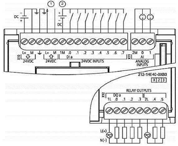
Figure 1. S7-1200 Programmable Controllers
The limit switch is the main component of the control unit, which can make the contact voltage greater than AC380V. It is mainly used for protection function and sequence control function, and its structure is mainly divided into circuit output part and detection part. The application of limit switches needs to be designed in combination with the installation method and mechanical structure. If the limit switch is small in size, it can be considered to be installed inside the mechanical structure, and in order to protect the internal circuit, it can be equipped with a corrosion-resistant metal enclosure. The internal circuit of the piston type limit switch has a pair of normally closed contacts and normally open contacts, which can fully satisfy the design requirements. The main circuit design of this system is the circuit design of two stepper motors, which are the front and rear moving stepper motor and the up and down moving stepper motor. The design of the main circuit is shown in Figure 2.
The stepper driver whose normal operation requires a DC24V input voltage, provides a pulse input signal as well as a direction signal through the programmable controller [6]. The minimum step angle of the stepper motor can be adjusted using a dip switch, which in this system is set at a step angle of 1.5 degrees. In addition to this, the stepper motor should also be set to a two-phase hybrid, with a fine fraction of two-phase eight beats and a maximum set current of 3.0 A.
The stepper driver wiring is mainly divided into three parts, the power input part is AC220V, the access terminals are L+ and N. The terminals of the programmable controller output are connected to the stepper driver, which can realize the forward and reverse control of the stepper motor [7].
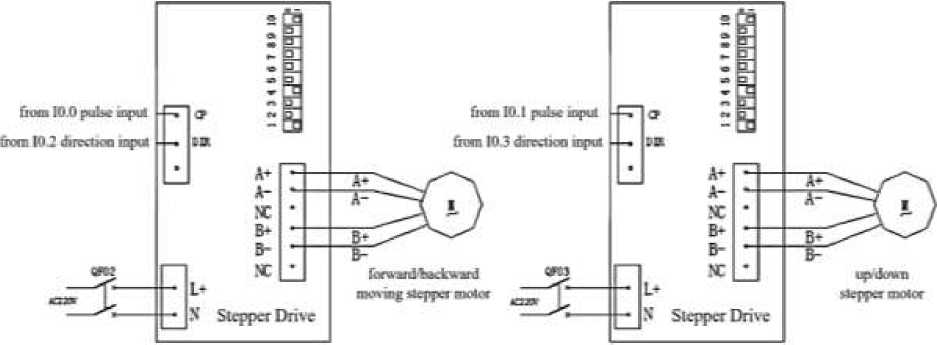
Figure 2. Motor circuit wiring diagram
This design system of AC oil pump dynamic source circuit design, rated voltage AC220V. the main purpose of the work is the active source circuit design on a special oil pump motor for AC wiring and oil pump power circuit design. Perforating machine under pressure force 200kG, speed 0.8m / s considered calculation, power calculation:
P = MxGx V/K
M — the weight; G — the acceleration of gravity; V — the velocity; K — the safety factor.
According to this calculation, the traction power is 1423W, and the inverter motor needs to be selected as 2kW. The design of the motor oil pump active source circuit mainly involves thermal relays, AC contactors and DC circuit breakers. In this self-locking automatic control circuit, when the contactor contactor coil is energized, the main contactor contact is sucked by the coil and the motor will start to rotate, and when the contactor contactor coil disconnects the power it will return and the motor will stop rotating. The ladder design inside the programmable controller is used to build the self-locking control circuit. According to the analysis of the design results, this system determines the input and output parts of the programmable controller of the system, which need to process 10 function signals and 6 execution signals respectively. The CPU1214C is selected as the control unit of the system, and DC24V is adopted as the power supply voltage of the input and output parts. The power supply module converts AC220V to DC24V for CPU power supply and input and output parts [8]. The PLC peripheral wiring circuit design is shown in Figure 4.
AC»MV
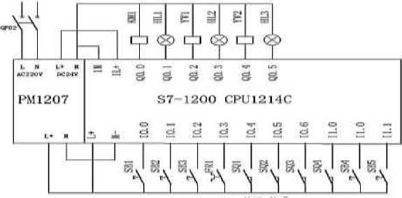
Figure 3. PLC circuit schematic
The main content of the I/O assignment design of the perforator control system is to assign addresses to the external input and output signals of the system. The subsequent software and hardware design is based on this address assignment design. The software design part first needs to make the corresponding address assignment inside the program to facilitate the compilation and design of the program. Problems found in the debugging system link can be identified by searching the I/O address table to determine the location of the fault, and then analyze the cause of the fault, and then take targeted solutions, which can be seen that the I/O allocation design provides great convenience for the subsequent system debugging [9]. In this paper, the input and output functions of the system are determined based on the process analysis results and expected requirements of this system, based on which the specific I/O allocation design for these input and output functions is carried out, and Table 1 shows the results of the specific system I/O allocation design in detail.
Table
I/O ALLOCATION DESIGN TABLE
|
Input Function |
Input Address |
Output Function |
Output Address |
|
Oil pump start/stop button |
I0.0 |
Oil pump contactors |
Q0.0 |
|
Fast down button |
I0.1 |
Pump operation indication |
Q0.1 |
|
Stop button |
I0.2 |
Fast down solenoid valve |
Q0.2 |
|
Thermal overload relay |
I0.3 |
Fast down indicator |
Q0.3 |
|
Fast down limit switch |
I0.4 |
Quick-release solenoid valve |
Q0.4 |
|
Quick-release limit switch |
I0.5 |
Quick rewind indicator |
Q0.5 |
|
Fast down limit switch |
I0.6 |
||
|
Quick-reverse limit switch |
I0.7 |
||
|
Quick-release pushbutton |
I1.0 |
||
|
Zero button |
I1.1 |
The S7-1200 programmable controller was used as the main control component in the design of the system tested, and the TIA Protherm V14 software was chosen as the dedicated programming software [10]. This software has mature technology and very powerful features that allow the design of visualization, programming and device configuration in one collection, enabling online monitoring, downloading of programs, visualization compilation, compilation of programs, device configuration, and remote stopping or starting of devices [11]. This software has a rich set of instructions and powerful functions to compile programs for all types of control schemes and supports a wide range of communication protocols. In addition, the software can download device programs through a dedicated MPI cable, set the correct communication address and baud rate and select the appropriate driver to be able to communicate with the programmable controller through the dedicated MPI cable, thus enabling online monitoring and program download and upload [12].
When the oil pump starts to run, the system function flow of the piercing machine mainly includes the start and stop of the hydraulic pump, the fast-down, slow-down, pressure-holding and fast-up actions of the piston. The program flow of the system is shown in Figure 4.The flow design of the home position program is shown in Figure 5.
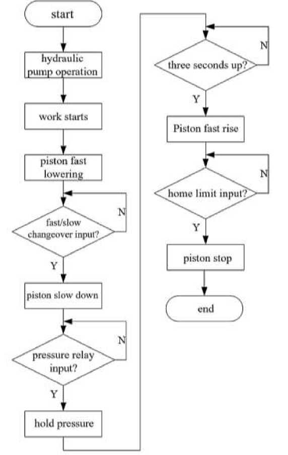
Figure 4. Main program flow chart
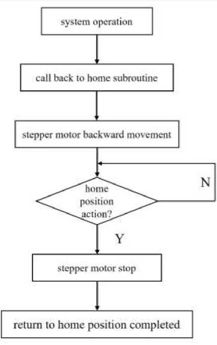
Figure 5. Function diagram of the return home program
After the system runs the "home program", the corresponding subroutine will be called, and the motor will execute the move back instruction until it touches the home limit switch, then it will stop, after the program is executed, the system will enter the standby state and wait for the next instruction. When the fast-forward button is clicked, the punch mechanism of the piercing machine starts to descend rapidly, when descending to the lower limit of SQ 1 , the punch mechanism turns to work-in descending, when touching the limit of SQ 3 , the punch mechanism starts to rise, when touching the upper limit of SQ 2 , the punch descends rapidly, and so on [13]. When the thermal relay fails, the oil pump stops and the system stops running. Figure 6 shows the control flow chart of this system in detail.
The configuration of the system is designed using Protherm V14 software for adding devices according to the programming of S7-1200, and the system configuration uses CPU1214C for the programmable controller configuration devices. The address setting for the Ethernet port is 192.168.0.1 [14]. Each input part and output part of the CPU is configured and the name is set. The specific configuration diagram is as follows. Following these steps, the address and variable name of each variable in the system are added, and the type of the variable is determined, which generally includes "character type", "switch type", and "value type". Once established, the variables are stored in the database [15]. After all the variables in the database are created, the screen is designed and compiled. The toolbox is used to select the content to be compiled, which generally contains the addition of buttons, the addition of various trend graphs, the modification and addition of fonts, and the addition of pipes [16]. In the bitmap, you can find the corresponding image to make the screen meet the process requirements of the site to complete the whole configuration design.
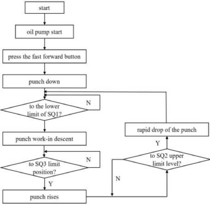
Figure 6. Control flow chart of this system
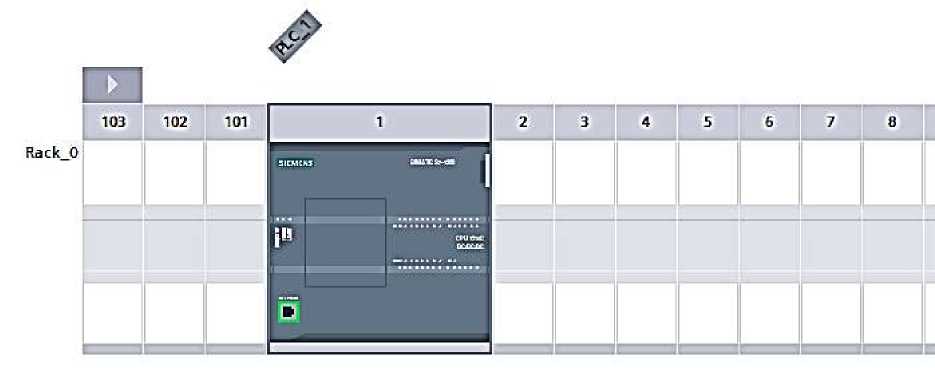
Figure 7. Software configuration diagram
The main process is to start the hydraulic pump and the three-way solenoid valve to control the rise and fall of the piercing machine according to the fixed process, and to switch the action through the limit switch. The system analysis of the hydraulic schematic of the piercing machine, the selected hydraulic cylinder is a single piston hydraulic cylinder, solenoid valve is a three-way four-way solenoid valve, through the S7-1200 CPU1214C system hardware and software design, system design through the sequential control method, according to the piercing machine fast forward - work in — fast backward three stages of the program design and process design.
The following conclusions can be obtained by summarizing the whole text:
-
(1) The software and hardware parts of the system process 10 functional signals and 6 execution signals through programmable controllers combined with PLC circuit design. Special programming software is used to complete the design of the main program and subroutines to realize the control and communication functions of the system, which greatly improves the degree of automation.
-
(2) Compared with the complex circuit design, this paper achieves the control requirements with a simpler circuit design, which makes the maintenance of the system simpler.
-
(3) This paper realizes the combination of perforator system and IOT through configuration design, which provides an innovative idea for the electrical system of perforator.
References Programmable controller based piercing machine system design
- Wang, Z., Li, S. (2019). Design of EDM penetration detection device based on 51 microcontroller . Automation Technology and Applications, 38, (03), 168-171.
- Luo, T., Liu, J., Zhu, Z. (2019). Status and improvement of the process and equipment of seamless steel pipe slant rolling perforating machine. Steel Pipe, 48, (03), 1-8. https://doi.org/10.19938/j.steelpipe.1001-2311.2022.5.08.13
- Long, Y., Yin B., Liang S. (2019). Application of PLC and touch screen in the control system of cylinder lampshade drilling machine. Light Industry Standard and Quality, (05), 110-111.
- Lin, F. (2017). PLC-based configuration simulation design of cross slide drilling machine. New Technology New Process, (12), 12-15.
- Griffin, A. S., Mariano, R., Hauck S. K., Hauck E. F. (2020). Inferolateral thalamic ischemia secondary to PCA P2 perforator occlusion mimics MCA stroke syndrome. Neurosurgical review, 43, (1), 11-13. https://doi.org/10.1007/s10143-019-01211-3
- Gao, J. (2012). Research on conical piercing process of high-strength large-diameter seamless steel pipe. Taiyuan University of Science and Technology, 7-9.
- Zhang, B. (2013). Analysis and Numerical Simulation of Influence Parameters of Conical Roll Diagonal Perforation Process. South China University, 1-5.
- Tang, J. (2007). Motor and Drag. Higher Education Press, 51-52.
- Li, Y. (2009). Application of PLC in the control system of perforating machine. Journal of Wuyi University, 17, (1), 22-25.
- Liu, J. (2014). Design and implementation of PLC-based large hydraulic piercing machine. Journal of Southwest Normal University, (39), 79-81.
- Wang, H. (2015). PLC-based punching device control system. Machine tools and hydraulics, (43), 9-12.
- Jia, B. (2008). Mechanical analysis and numerical simulation of the piercing process in a two-roller oblique piercing machine. University of Science and Technology of Liaoning, 6-9.
- Stockman, M., Dwivedi, D., Gentz, R. (2019). Detecting control system misbehavior by fingerprinting programmable logic controller functionality. International Journal on Critical Infrastructure Protection, 26, 7-8. https://doi.org/10.1016/j.ijcip.2019.100306
- Hadi, N., Yee, L. H., Annuar, K. (2019). Development of an automatic can crusher using programmable logic controller. International Journal of Electrical and Computer Engineering, 9, (3), 17-19. https://doi.org/10.11591/ijece.v9i3.pp1795-1804
- Dang, J., Gu, Y., Zhou, J. (2019). Design of Domestic Sewage Treatment System Based on Programmable Logic Controller. Journal of Scientific Research and Reports, 1-10. https://doi.org/10.9734/jsrr/2019/v23i230119
- Ma, R., Cheng, P., Zhang, Z. (2019). Stealthy Attack Against Redundant Controller Architecture of Industrial Cyber-Physical System. IEEE Internet of Things Journal, (99), 1-1. https://doi.org/10.1109/jiot.2019.2931349
