Project for a drainage system for rainwater

Author: Bosca Daniele
Journal: Антропогенная трансформация природной среды @atps-psu
Section: Проблемы городской среды
Article in issue: 2, 2016.
Free access
In article about the project for a drainage system for rainwater.
Rainwater, waste water, sewerage, trento
Short address: https://sciup.org/147226762
IDR: 147226762 | UDC: 631.62
Проект дренажной системы для дождевой воды
В статье описывается проект дренажной системы для дождевых вод.
Text of the scientific article Project for a drainage system for rainwater
Sizing and checking sewer. Sewerage services to the area object of intervention will feed into the existing white sewer line on Via Milano, located in the Trento’s city. In order not to further overload the white sewer system from the current situation, as well as providing for the same standards of Reclamation Consortium in order to the new urbanization, it will construct a tank top, such as to temporarily contain additional water supplies linked to changed morphological conditions of the area, resulting in the occurrence of major rainfall events. The Consortium of Reclamation has set a limit, beyond which it must be laminar, a ow rate of about 10 1/s per hectare urbanized.
Dimensional characteristics description.
It will be provided for:
-
- Total housing units n. 34 u.i
-
- Population equivalent compartment n. 86 ha.
The collecting system of waste water will be realized with the use of concrete pipes vi-brocompressed of the resistance of 450 kg / cm 2 with a diameter of 200 mm and 100 mm. The pipes will be intercepted by prefabricated manholes a.c. worked in such a way as to obtain the perfect impermeability and mechanical strength RcK> 400 kg / cm \ at intervals not exceeding 25 meters. And at the same we will be provided for connections to residential areas.
Calculation of the ow rate of water.
The ductwork sizing is calculated based on the determination of the rain brought by disposing in less favorable conditions. That determination is the time series of annual maximum rainfall values, which have led to prudently consider the following values as the basis for calculation: -Rainfall intensity = 0.05 m / h with ten-year return period; - Per-centage of Hing the pipe = 50Planimetric examination determines an impermeable surface weighing on the sector network Qp = ow alpha = coe-cient of inux
® Daniele Bosca, 2016
area waterproof = 0.60 A = area under I = rainfall intensity = 0.050 in / h psi = delay coe-cient = 0.80 Qp = (alfa x A x I x psi) / 0.36 Qp = ((0.60 X 0.648 x 0.050 x 0.80 )/0.36) = 0.043 mc/sec.
Sizing of the water network. The verication is carried out by adopting a value of H / Di (equal to 60% of the pipe Hing percentage). The calculation is performed in the terminal node of the compartment before placing in the existing waste water net.
Conduct internal diameter conduct internal diameter (600mm) = 100 mm Slope (I) = 0.1
Rouglmess coe-cient (Gauckler-Strickler) cis = 0.8 tubes Degree of Hing = 60%
Di = diametro intemo del tube (mn)
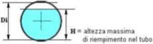
Figura 1.1: The internal diameter of the tube
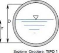
Flow limitation.
Qamm = muA(2gh)l/2 where:
Qamm = allowable euent ow rate to the receptor mu = 0.6 h = swing above the axis of the exhaust duct
Amax = Qamm / mu (2gh) № = maximum section of the drainage Pipe
Hydraulic swing of 0.64 m is Amax = Qamm / mu (2gh) У2 = = 2.797 mm2
r = (Amax=3:14) = 29.85 mm d = 59.70 imnDN 125
Drainage system structure.
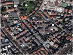
Figura 2.1: Territorial placement
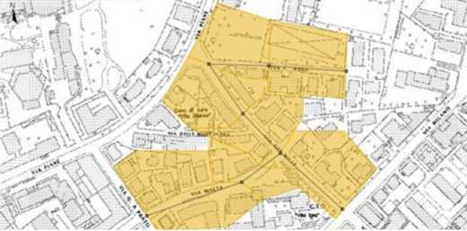
Figura 2.2: Drainage tracking
Drainage system design: study procedure and calculation followed by its simulation.
-
1) Choice of location area through Udig platform, lias been selected as the cartographic reference system EPSG 3003;
-
2) Creation of the wells according to the road structure and the presence of buildings and pipe already on site, with relative location of choice;
-
3) The addition of the pipes was made considering the morphology of the terrain and the additional presence of underground structures;
-
4) The parameters used for the piping shall relate to the case study:
Runo coe-cient given by the formula:
H02V„, ■IW.y.Jb,,-sj
chosen equal to 0.5;
calculation of the average access time to the network:
chosen equal to 0.39;
Gauckler-Strickler coe-cient for the pipe according to records:
Table 3
|
Tub»fk>ne ТиЫ nuovt PE. PVC. РЯЛ/. Heme. Accwo Inox |
V 0 • 0.02 |
Bazin V |
Kutter m |
Strickler к |
|
Tutu nuovt Gres. Ghrse rivestit». Accwo |
0.05 - 0.15 |
< 0.06 |
< 0.12 |
120 - 100 |
|
TutH in Cemento ortfmwto, tutx con lievi incrostazion |
0.10 • 0,4 |
0.10 |
0,12 |
105 • 85 |
|
TutN con mcrosrazioni e dcpositi |
0.6 - 0.8 |
0.18 |
0.25 |
80 - 90 |
Coefficient! di scabrezza delle tubazioni
given by the formula:
Q=K,R^-Ti in our case we are equal to 65;
the minimum choice slope equal to 0.1;
the type of always circular section.
-
5) have been associated with the draining of the various areas for the dierent pipes into which;
-
6) using the program joined Udig. TrentoP it was possible to simulate the drainage system
parameters in input data parameters such as: the parameters of the pluviometrie possibi-p lity curve project “a = 29.9” in [mm / h n] and “n = 0.46®;
the alignment of the free hair/heaven/funds (1);
the tangential stress at the bottom (2.5);
the degree of Hing (0.7);
-
7) the estimated compiler internal parameters and temporal parameters;
-
8) are then placed the parameters for the diameters and thicknesses commercial, with a relative closure of the basin by a given pipe.
The results obtained are characterized by parameters such as ow rate (1 / s). udometrico coe-cient (1 / s * ha). residence, rainy weather time, time to peak, average speed, slope, coimnercial diameter of the fund, share of free surface area plotted.
Drainage system design: simulation.
Loading the design data, we can do a simulation of what can happen in the verication of sewer according to several steps, using as Udig tool:
-
1) Load the initial parameters and said optional parameters for calibration;
-
2) Load rain data starting from the parameters a = 29.9 and n = 0.46 to derive a raining time of 30 with relative time step of 15 minutes and 60 minutes duration of the simulation, then inserting the ow rates and the degrees Hing.
What lias occurred in our case is that the pipe lias been pressurized.
To resolve the problem then it is started to increase the diameter of the downstream piping and proceeding increasing, from time to time, the diameter of the most upstream piping, there is the test veried.
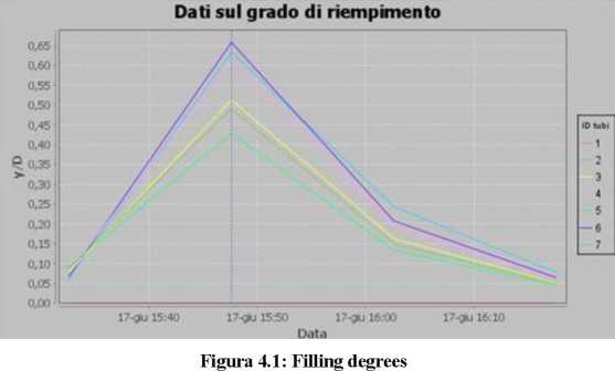
It was then made a further verication with duration of 150 minutes and simulation were obtained the graphs of the ow in the sewer and the data on the degree of Hing:
Conclusion. Generally, rain water runo can not be directly delivered to the drainage network without treatment, and this principle should be reected in the standard and in good management. However it is known that in dense urban fabric, the lower remediation network has disap-peared. replaced by sewerage, waste water and mixed water.
Portale nella fognatura
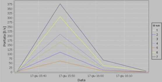
Figura 4.2: Dierent drainage ow
It thus takes on meaning to face the problem of how the rain water should be managed in tliis context. The main event is of course the design of new residential building works or not design (urbanization, construction of main roads, etc.) or the adaptation of existing lots.
The basic logic tliat the designer should be taken from the 260relimnarv design document is the search of the separation of the waste according to the quality.
The Sewerage Regulations, which is known as the contact element between the Area Au-thority and the managing body of the sewage system, always touches the topic, but it is not. to date, standardized.
Tliis. however, makes sense if we consider that we have a Regulation as close to the ter-ritory of interest, it is a moment of clarication of construction techniques to be adopted in relation to the local realities of the network. Also it must always remember tliat the Manager of the sewage system is nanced with the rate relative to the aqueduct service.
It follows that in principle the competence of the same falls, unless otherwise determined by conventions, the only component of the waste water generated by aqueduct consumption. In unit schemes, not being possible to distinguish, the Manager bears obviously the rain part of the waste water. From the design point of view, the major distinction obviously occurs at the level of the delivery type. Since the water inside the lots must always be handled through separate schemes, very dierent it is the situation in which the backbone connection is a unit or separate type.
A crisis of waste water network is in fact, generally local, and, though serious, does not lead to the spreading of sewage. During the presizing the absolute limit is set in the coef-cient udometric equal to 10 1/s ha, that is certainly not easy to reach in tight areas and strongly waterproofed. Note, however, that this practice is considered simple preliminary assessment, as it will be then the manager to deliver an opinion on the project and, if positive, the next connection authorization.
A nal nod, dutiful, the rst rain. Here too, the Regulation species that charges for run-о water should be provided for collecting and laminating systems, then pertaining to the sewer system, the volume at least equal to the rst rain.
What with the dual purpose of not deliver water charges to the waste net (intercepts all the rst rain) and not to overload the waste water system (volumes collected are returned to the black or mixed network with the laminating equipment that is appropriate).
In summary:
-
- To develop the design from the earliest stages in concert with the Park Authority
-
- Always deliver the waste water to surface water bodies
-
- If there are not the appropriate bodies, to devise solutions
that have the nature of im-permanence, in relation to the evolution of the territory into separate delivery to separate network systems (separate internal distribution patterns, points)
-
- Place of mandatory limits to pluviometric coe-cients not higher than those of their re-mediation (in particular as dened in these guidelines)
-
- Set up systems for the collection of the rst rain and the rolling deliver it.
References Project for a drainage system for rainwater
- Alegre, H. et al. Performance Indicators for Water Supply Services, Second Edition, IWA Publishing, 2006.
- Deb, K. &Goel, T. Controlled elitist non-dominated sorting genetic algorithms for better convergence, Evolutionary Multi-criterion Optimization 2001, ed. E. Zitzler et al., LNCS 1993, Springer, 2001, 67-81.
- Halhal, D., Walters, G.A., Ouazar, D. & Savic, D.A. Water network rehabilitation with structured messy genetic algorithm, Journal of Water Resources Planning and Manage-ment, 1997, 123, 137-146.
- Lambert, A.O. International Report on Water Loss Management and Techniques, Water Science and Technology: Water Supply, 2002, 2(4), 1-20.
- Lambert, A.O. What do we know about pressure:leakage relationship in distribution systems?,Proceedings of the IWA Conference on System Approach to Leakage Control and Water Distribution Systems Management, Brno, 2001.
- M.Nicolini, P.Bertola,Ferrara:Approvvigionamentoe Distribuzi one Idrica: Esperienza, Ricerca ed Innovazione,28-29 giugno 2007.
