Prospects for the development of high-voltage power supply systems of spacecraft with a charge-discharge regulator

Author: Filonova M. M.
Journal: Siberian Aerospace Journal @vestnik-sibsau-en
Section: Aviation and spacecraft engineering
Article in issue: 1 vol.21, 2020.
Free access
Changing the low-voltage level of the output load power bus (27–28 V) in the power supply system (PSS) of the spacecraft (SC) to a high-voltage (100 V) allowed us to significantly reduce the SC mass in connection with the reduction in the mass of cables and energy converting equipment (ECE). However, a number of problems have arisen related to the difficulty of matching the increased voltage levels of energy sources and loads, taking into account the necessary level of reliability of the PSS. Therefore, the issues of choosing the PSS structure and methods for developing ECE are relevant and priority task facing their developers. To date, in the field of development and creation of high-voltage high-power PSS of SC, a promising direction is their design based on integrated ECE modules, in particular, on the basis of modules of charge-discharge regulators (CDR) of accumulator batteries (AB). In the article, a calculation and comparative analysis of the SC PSS structures with the connection of the CDR module to the solar battery (SB) bus and with the connection of the CDR module to the output load power bus is performed. In the course of analysis of the results obtained, it was found that both options for the PSS implementation can be optimal depending on the given curve of the SC load and the requirements for the PSS for specific energy, weightdimension and other characteristics. The final choice of the SC PSS structure should be made subject to the specific power of the ECE and the subsequent calculation of the weight-dimension characteristics of the alternative PSS. Simulation of two options for the implementation of the AB CDR module was carried out: a push-pull converter with one inductor and a Weinberg converter with a magnetically coupled inductor and an additional power diode. It is established that both investigated options can be used in the development and creation of the CDR module of the highvoltage PSS of spacecraft. However, the design of CDR module based on the Weinberg converter can significantly reduce the values of the used inductors and output capacitors subject to the required levels of output voltage ripple.
Spacecraft, power supply system, maximum power point tracking mode, battery charge-discharge regulator, Weinberg converter.
Short address: https://sciup.org/148321725
IDR: 148321725 | UDC: 621.31 | DOI: 10.31772/2587-6066-2020-21-1-96-105
Text of the scientific article Prospects for the development of high-voltage power supply systems of spacecraft with a charge-discharge regulator
Introduction. For the purpose of high-quality and timely performance of tasks implemented by spacecraft, it is necessary to develop their reliable power supply systems (PSS) with the most improved specific energy and dimensional mass characteristics. One of the first and main tasks that arise during the development and creation of PSS SC is the choice of their structure. The PSS must implement a reasonable consumption of the power generated by solar and accumulator batteries (SB and AB) in order to provide consumers with the required types of electric energy with the specified quality indicators. The problem is solved by calculation and comparative analysis of options for the PSS structures, followed by selection of the most optimal one from the point of view of the accepted criteria for system efficiency (weight, dimensions, energy characteristics, etc.) [1].
Since the 70s of the 20th century, the development of PSS is based on structural schemes with serial or parallel voltage regulators (VR) of the SB [2; 3]. The output voltage of the stabilized load supply bus was mainly 27–28 V. The most widely used parallel-serial structure in Russia allows implementing the maximum power point tracking mode of the SB and its maximum usage [4; 5]. Such PSS are implemented on SC developed by the leading companies of the Russian space Agency: JSC “Academician M. F. Reshetnev “Information Satellite Systems” (Zheleznogorsk), JSC “NPO n.a. S.A. Lavochkin” (Khimki), JSC “RCC “Progress” (Samara). They are widely used as at a low voltage output of the PSS the maximum value of open circuit voltage of SB at the moment of exit from the Earth shadow does not exceed 80 V. That allows to easily compiling a list of used power items and materials. However, the schemes designed by traditional methods and worked out over many years of operation do not allow obtaining the necessary high quality indicators, taking into account the constantly increasing requirements for improving the characteristics of the PSS.
The creation of a high-voltage (100 V) PSS for automated SC allows significant reducing of the mass of SC in connection with the reduction of the mass of cables and energy converting equipment (ECE). However, there is a number of issues appeared due to the rise of higher voltage power sources and their correlation with the necessary level of reliability of PSS SC. The main problem is an increase in the SB voltage when the SC leaves the Earth's shadow, which is unacceptable because of the possibility of electrostatic discharges between the SB photodiode chains and current-collecting elements and the occurrence of an emergency mode of the PSS [6; 7]. To limit the voltage on the SB, it is necessary to use special devices or implement the modes of operation of the PSS that do not allow increasing the voltage on the SB more than 180V [8].
The developers of high-voltage PSS for large space platforms (up to 20 kW) for geostationary orbit solved the problem by selecting the optimal shunt structure at that time, in which the output voltage on the load is stabilized by limiting the voltage on the SB during the entire service life. Examples of such space platforms are Express-2000, Spacebus 4000, etc. [5]. The use of shunt PSS is optimal for achieving high energy characteristics in the case of geostationary orbits with constant illumination and a uniform cyclogram of the SC load. However, the calculation of the PSS is performed at the end of the service life under conditions of degradation of energy sources, which negatively affects its characteristics. Until the SB reaches the characteristics corresponding to the degradation state and the worst operating conditions in this structure, it will be significantly underutilized in capacity.
An urgent task for today, the solution of which will allow to achieve a significant improvement in the characteristics of high-voltage PSS of SC, taking into account the non-simultaneous processes of charge and discharge of AB, is the development of PSS with modules of battery charging and discharge regulators [9].
Structures of a high-voltage PSS with a battery charge-discharge regulator. Fig. 1 shows the options for implementing the structures of high-voltage PSS with the CDR module of AB, where L is the load.
Tab. 1 shows the ratio for determining required levels of current values generated by the SB and AB power, taking into account the efficiency of PSS in accordance with the operation modes of the alternative variants of PSS and graphs of SC load.
Tab. 1 symbols: P БС ( τ ) – current value of SB power BS, P Н ( τ ) – current value of load power, P АБ_ЗУ ( τ ) – current value of the AB power charge, P АБ_РУ ( τ ) – current value of the AB discharge power, η РН ( τ ) – the efficiency coefficient PH, η ЗУ ( τ ) – efficiency coefficient of CDR module in AB charging process, η РУ ( τ ) is the efficiency coefficient of the CDR in the discharging of AB, η АБ ( τ ) – the rate of AB.
For arbitrarily composed abruptly variable cyclograms of the SC load and the graph of the generated SB power (fig. 2, 3) the processes of energy flows in the PSS and the calculation taken at the same values of the efficiency of ECE (95 %) were investigated with objective of comparative analysis of alternative structures of PSS and determination its optimal structure, subject to minimizing the overall power of ECE [1].
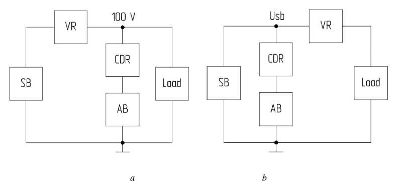
Fig. 1. The structure of the high voltage SC PSS with the connection of the battery charge-discharge regulator to the load output bus ( a ), to the solar battery bus ( b )
Рис. 1. Структуры высоковольтных СЭП КА с подключением модуля ЗРУ к шине питания нагрузки ( а ) и шине солнечной батареи ( б )
Table 1
Current values of SB, AB and load capacities in the PSS
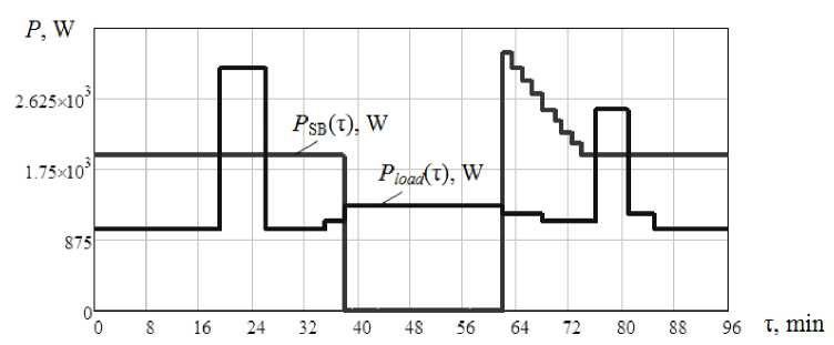
Fig. 2. Load cyclogram 1 and graph of the SB generated power in the PSS
|
Mode of energy supply loads: |
PSS with connection of the CDR module to the load bus |
PSS with connection of the CDR module to the SB bus |
|
From SB |
P Н ( τ ) = P БС ( τ ) ⋅ η РН ( τ ) |
P Н ( τ ) = P БС ( τ ) ⋅ η РН ( τ ) |
|
From SB and charge of AB |
P БС ( τ ) = P Н( τ ) + P АБ_ЗУ( τ ) η РН ( τ ) η ЗУ( τ ) |
P БС ( τ ) = P Н( τ ) + P АБ_ЗУ ( τ ) η РН( τ ) η ЗУ( τ ) |
|
From SB and discharge AB |
P Н( τ ) = P БС( τ ) ⋅η РН( τ ) + +P АБ_РУ( τ ) ⋅ η РУ( τ ) ⋅ η АБ( τ ) |
P Н( τ ) = P БС( τ ) ⋅η РН( τ ) + +P АБ_РУ( τ ) ⋅η РУ( τ ) ⋅ η РН( τ ) ⋅ η АБ( τ ) |
|
From AB |
P Н ( τ ) = P АБ_РУ ( τ ) ⋅ η РУ ( τ ) ⋅ η АБ ( τ ) |
P Н( τ ) = P АБ_РУ( τ ) ⋅ η РУ( τ ) ⋅ η РН( τ ) ⋅ η АБ( τ ) |
Рис. 2. Циклограмма нагрузки 1 и график генерируемой БС мощности в СЭП
Table 2
Calculated values of the mass of energy sources and ECE capacities in the PSS
|
Parameter |
PSS with connection of the CDR module to the load bus |
PSS with connection of the CDR module to the SB bus |
|
Cyclogram load 1 |
||
|
SB mass, kg |
39.57 |
39.57 |
|
AB mass, kg |
46.65 |
49.11 |
|
Maximum calculated power of CDR in CR mode, W |
1835.4 |
1932.0 |
|
Maximum calculated power of CDR in DR mode, W |
3157.9 |
3324.1 |
|
Maximum calculated power of VR, W |
3195.1 |
3157.9 |
|
Cyclogram load 2 |
||
|
SB mass, kg |
23.78 |
23.78 |
|
AB mass, kg |
36.32 |
38.23 |
|
Maximum calculated power of CDR in CR mode, W |
848.8 |
893.4 |
|
Maximum calculated power of CDR in DR mode, W |
1421.1 |
1495.8 |
|
Maximum calculated power PH, W |
1920 |
1421.1 |
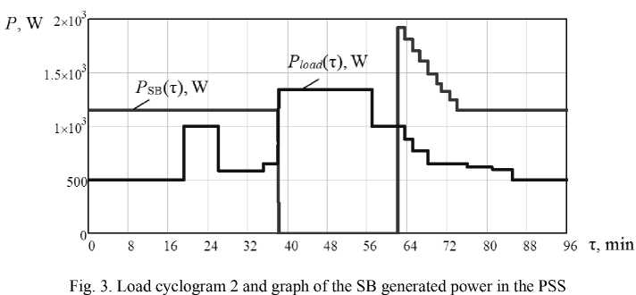
Рис. 3. Циклограмма нагрузки 2 и график генерируемой БС мощности в СЭП
Tab. 2 shows the main design parameters for alternative versions of the EPA for different cyclograms of the SC load.
Within the cyclogram load 1 of the SC, the mass of the SB in the alternative versions of the PSS is the same. The mass of the AB in the PSS with the connection of the CDR module to the SB bus is greater by 2.46 kg. However, given that in practice the AB are selected with a certain margin, the mass of the AB for both versions of the PSS can be equal.
The maximum calculated power of the CDR in the CR mode and in the DR mode in the PSS with the connection of the CDR module to the SB bus is greater by 166 W and 97 W, respectively, compared to the maximum calculated power of the CDR of the alternative implementation of the PSS. However, in the PSS with the connection of CDR to SB bus maximum design power of VR is 37 W less because some part of SB generated power is consumed by CR to provide AB charging.
Within the cyclogram load 2 of the SC, the mass of the SB in the alternative versions of the PSS is the same. The mass of the AB in a PSS with the CDR module con- nected to the SB bus is greater by 1.91 kg. However, as described above, in practice, the mass of the AB for both versions of the PSS may be equal.
The maximum calculated power of the CDR in the CR mode and in the DR mode in the PSS with the connection of CDR to the SB is 44.6 and 74.7 W more respectively, compared to maximum calculated capacity of CDR in alternative PSS. However, in a PSS with the CDR module connected to the SB bus, the maximum calculated power of the WL is less by 498.9 W.
In the course of studying the processes of distribution of energy flows in the PSS from tab. 2 it can be seen that the SC PSS with a sharply variable load cyclogram 1 is advisable to design according to the implementation option of the PSS with the connection of the CDR module to the output bus of the load power supply. However, when the load cyclogram is 2, it is advisable to design the SC PSS according to the implementation option of the PSS with the connection of the CDR module to the SB bus. The final choice of the PSS structure should be made subject to taking into account the specific power of the energy-generating equipment used and the subsequent calculation of the dimensional and mass characteristics of alternative PSS options.
Simulation of CDR module of the accumulator battery. One of the options for the schematic implementation of the CDR module is its development based on a pushpull converter with a single inductor [10].
In the LTspice IV environment, simulation models of the CDR based on a push-pull converter with a single inductor for the charge and discharge modes of the AB were developed (fig. 4, 5). The parameters of the elements of the simulation model of CDR: accumulator battery voltage in the discharge mode UАБ_РАЗ is equal to 55 V; the voltage of the output power bus load UН is 100 V; the inductance of each winding of the transformer TV1.1 and TV1.2 is equal to 35 µH; inductance of the inductor L4 is 9.4 µH; frequency f is equal to 100 kHz for model transistor IRFP4668; diode model Mbr20200ct; the capacitor of 7.4 µF and 32 µF. It is accepted that the output voltage ripple should not exceed 1 %. Converter power in the discharge mode is equal to 1500 W at a voltage level of the output power bus load of 100 V. The converter power in the charge mode is 900 W at a voltage level of charging AB equal to 60 V.
Fig. 6, 7 show the waveforms of the voltages flowing in the converter in the discharge and charge mode of the AB.
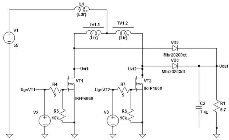
Fig. 4. Simulation model of CDR based on the push-pull converter with one inductor in AB discharge mode
Рис. 4. Имитационная модель ЗРУ на основе двухтактного преобразователя c одним дросселем в режиме разряда АБ
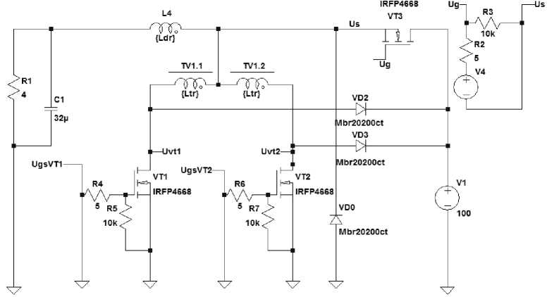
Fig. 5. Simulation model of CDR based on the push-pull converter with one inductor in AB charge mode
Рис. 5. Имитационная модель ЗРУ на основе двухтактного преобразователя c одним дросселем в режиме заряда АБ
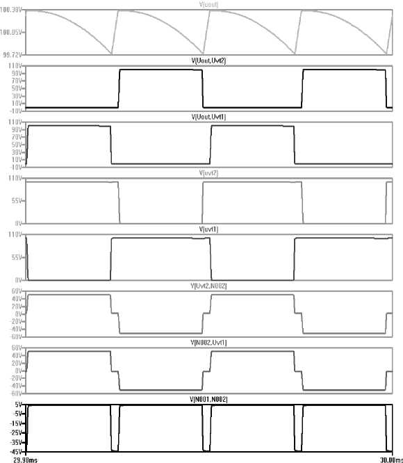
Fig. 6. Waveforms of CDR voltages in the AB discharge mode: V (out) – output voltage; V (out, Uvt2) and V (out, Uvt1) are the voltages on the diodes VD3 and VD2; V (Uvt2) and V (Uvt1) – voltage on transistors VT2 and VT1; V (Uvt2, N002) and V (N001, Uvt1) – voltage on the transformer windings TV1.2 and TV1.1;
V (N001, N002) – voltage at the inductor L4
Рис. 6. Осциллограммы напряжений ЗРУ в режиме разряда АБ: V(out) – напряжение на выходной шине питания нагрузки; V(out, Uvt2) и V(out, Uvt1) – напряжение на диодах VD3 и VD2; V (Uvt2) и V (Uvt1) – напряжение на транзисторах VT2 и VT1; V(Uvt2, N002) и V(N002, Uvt1) – напряжение на обмотках трансформатора TV1.2 и TV1.1; V (N001, N002) – напряжение на дросселе L4
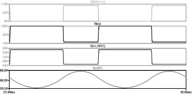
Fig. 7. Waveforms of CDR voltages in the AB charge mode: V (N002, Us) – voltage on the transistor VT3; V (Us) – voltage of diode VD0; V (Us, N001) – voltage at the inductor L4; V (n001) – AB charge voltage
Рис. 7. Осциллограммы напряжений ЗРУ в режиме заряда АБ: V (N002, Us) – напряжение на транзисторе VT3; V (Us) – напряжение на диоде VD0;
V (Us, N001) – напряжение на дросселе L4; V (n001) – напряжение заряда АБ
Another promising option for implementing CDR model is its circuit design based on a Weinberg converter with a magnetically coupled inductor and an additional power diode [11–15].
In the LTspice IV environment, simulation models of the CDR based on the Weinberg converter with a magnetically coupled inductor for the charge and discharge modes of the AB were developed (fig. 8, 9).
The parameters of the elements of the simulation model of CDR: accumulator battery voltage in the discharge mode UАБ_РАЗ equal to 55 V, the voltage of the output power bus load UН is 100 V, the inductance of each winding of the transformer TV1.1 and TV1.2 is equal to 35 µH, inductance of inductors L1.1 and L1.2 equal to 2.36 µH, the frequency f is equal to 100 kHz for transistor model IRFP4668, diode model Mbr20200ct, the capacitor is 2 µF and 32 µF.
Converter power in the discharge mode is equal to 1500 W (when UН = 100 V). Converter power in the in charge mode is 900 W (when the charge voltage of AB is 60 V).
Fig. 10, 11 show the waveforms of the voltages flowing in the converter in the discharge and charge mode of the AB.
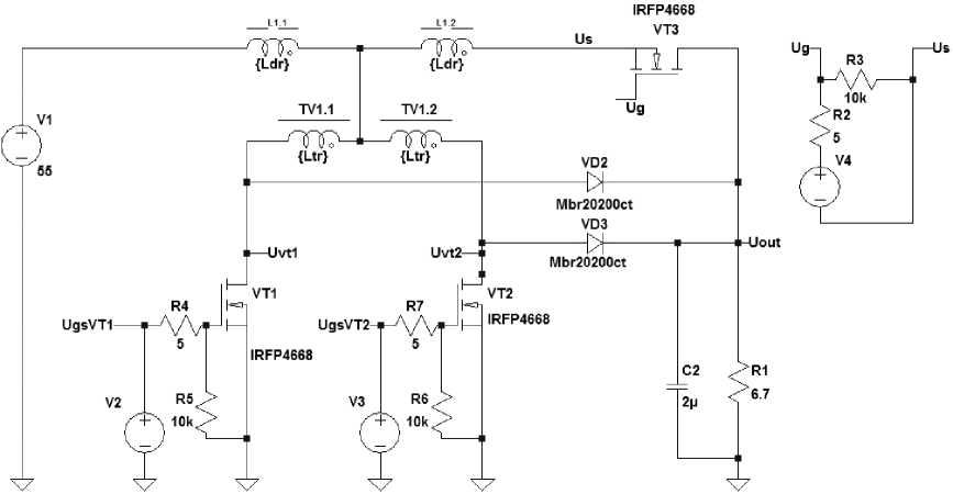
Fig. 8. Simulation model of CDR based on Weinberg converter with a magnetically coupled inductor in AB discharge mode
Рис. 8. Имитационная модель ЗРУ на основе преобразователя Вейнберга c магнитосвязанным дросселем в режиме разряда АБ
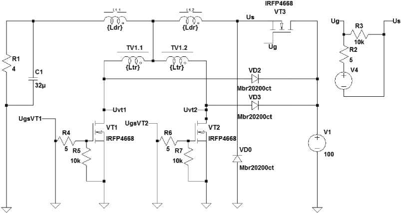
Fig. 9. Simulation model of CDR based on Weinberg converter with a magnetically coupled inductor in AB charge mode
Рис. 9. Имитационная модель ЗРУ на основе преобразователя Вейнберга c магнитосвязанным дросселем в режиме заряда АБ
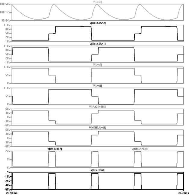
Fig. 10. Waveforms of CDR voltages in the AB discharge mode: V (out) – output voltage;
V (out, Uvt2) and V (out, Uvt1) are the voltages on the diodes VD3 and VD2; V (Uvt2) and V (Uvt1) – voltage on transistors VT2 and VT1; V (Uvt2, N002) and V (N002, Uvt1) – voltage on the transformer windings TV1.2 and TV1.1; V(N001, N002) and V (Us, N002) – voltage at the magnetically coupled inductor; V (Us, Uout) – voltage of transistor VT3
Рис. 10. Осциллограммы напряжений ЗРУ в режиме разряда АБ: V (out) – напряжение на выходной шине питания нагрузки; V (out, Uvt2) и V (out, Uvt1) – напряжения на диодах VD3 и VD2; V (Uvt2) и V (Uvt1) – напряжения на транзисторах VT2 и VT1;
V (Uvt2, N002) и V (N002, Uvt1) – напряжение на обмотках трансформатора TV1.2 и TV1.1; V (N002, N001) и V (Us, N002) – напряжения на магнитосвязанном дросселе;
V (Us, Uout) – напряжение на транзисторе VT3
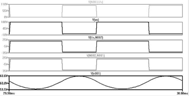
Fig. 11. Waveforms of CDR voltages in the AB charge mode: V (N002, Us) – voltage on the transistor VT3; V (Us) – voltage of diode VD0; V (Us, N002) and V (N002, N001) – voltage at the magnetically coupled inductor; V (n001) – AB charge voltage
Рис. 11. Осциллограммы напряжений ЗРУ в режиме заряда АБ: V (N002, Us) – напряжение на транзисторе VT3; V (Us) – напряжение на диоде VD0; V (Us, N002) и V (N002, N001) – напряжение на магнитосвязанном дросселе; V (n001) – напряжение заряда АБ
The implementation of the SRU module based on a Weinberg converter with a magnetically coupled choke and an additional diode makes it possible to reduce the nominal value of the choke inductance by 2 times and the output capacitor (in the AB discharge mode) by 3.7 times compared to a two-stroke Converter with a single choke, subject to the condition of ensuring an equal level of output voltage ripples (no more than 1 %) in the matched converters.
Conclusion. Nowadays, in the field of development and creation of high-voltage high-power SC PSS, a promising direction is the design based on combined modules of energy-generating equipment, in particular, taking into account the non-simultaneous processes of charging and discharging AB on the basis of combined CDR modules of accumulator batteries.
The study of the processes of energy flows in the PSS and of the comparative analysis found that both implementations of PSS can be optimal depending on the specified cyclogram of SC load and requirements for the specific energy and the weight dimension characteristics of PSS, as well as, for example, according to the requirements of restriction of currents of charge-discharge of AB, etc., which affects the redistribution of energy in PSS. In addition, the choice of the PSS structure should be made subject to taking into account the specific power of the energy-generating equipment used and the subsequent calculation of the weight dimension characteristics of PSS alternative options.
Based on the results of simulation of two variants of implementation of CDR module of AB, it was revealed that both studied variants can be used in the development and creation of the ECE of the high-voltage power supply system of the spacecraft. However, the development of a CDR based on the Weinberg converter allows reducing the ratings of the used inductors and output capacitors under the required levels of output voltage ripples.
References Prospects for the development of high-voltage power supply systems of spacecraft with a charge-discharge regulator
- Chernaya M. M. Method for calculating the energy characteristics and solar battery parameters of highvoltage power supply systems. Siberian Journal of Science and Technology. 2018, Vol. 19, No. 4, P. 651–657.
- Soustin B. P., Ivanchura V. I., Chernyshev A. I., Islyaev Sh. N. Sistemy elektropitaniya kosmicheskikh apparatov [Power supply systems of space crafts]. Novosibirsk, Nauka Publ., 1994, 318 p.
- Nesterishin M. V., Kozlov R. V., Zhuravlev A. V. [Comparative analysis of energy efficiency of energy converting equipment with parallel and serial solar battery power controller]. Doklady TUSURa. 2018, Vol. 21. No. 3. P. 98–102 (In Russ.).
- Chebotaev V. E., Kosenko V. E. Osnovy proektirovaniya kosmicheskikh apparatov informatsionnogo obespecheniya [Basics of design of information space vehicles]. Krasnoyarsk, Sib. State Aerokos. Univ. Publ., 2011, 515 p.
- Shinyakov Yu. A., Gurtov A. S., Gordeev K. G. at al. [The choice of the structure of power supply systems for low-orbit spacecraft]. Vestnik Samarskogo gosudarstvennogo aerokosmicheskogo universiteta im. akademika S. P. Koroleva. 2010, No. 1(21), P. 103–113 (In Russ.).
- Akishin A. I. [Impact of electrical discharges on solar panels]. Nauchno-issledovatel'skii institut yadernoi fiziki imeni D. V. Skobel'tsyna MGU. 2008, No. 4, P. 68–71 (In Russ.).
- Lesnykh A. N., Sarychev V. A. [The research of high-voltage power supply systems for space crafts with boost converter]. Vestnik SibGAU. 2006, No. 6 (13), P. 63–66 (In Russ.).
- Chernaya M. M., Shinyakov Yu. A. [Research and development of energy-converting equipment for highvoltage power supply systems for low-Earth orbit space remote sensing devices]. Sbornik materialov VII Mezhdunarodnoi nauchnotekhnicheskoi konferentsii K. E. Tsiolkovskii – 160 let so dnya rozhdeniya. Kosmonavtika. Radioelektronika. Geoinformatika. [Proc. of the VII International Scientific and Technical Conference named K. E. Tsiolkovsky]. Ryazan', 2017, P. 134–136 (In Russ.).
- Chernaya M. M. [Spacecraft Power Systems with Charger-Discharge Module]. Sbornik izbrannykh statey nauchnoy sessii TUSUR. 2018, Vol.1, No. 2, P. 163–166 (In Russ.).
- Yan Li, Trillion Q. Zheng, Qian Chen. Research on High Efficiency Non-Isolated Push-Pull Converters with Continuous Current in Solar-Battery Systems. Journal of Power Electronics. 2014, Vol. 14, No. 3, P. 432–443.
- Maset E., Ferreres A., Ejea J. B. et al. [High Efficiency Weinberg Converter for Battery Discharging in Aerospace Applications]. IEEE PESC Conf. 2006, Р. 1510–1516.
- Chen W., Rong P., Lu Z. Y. [Snubberless bidirectional DC-DC converter with new CLLC resonant tank featuring minimized switching loss]. IEEE Trans. Ind. Electron. 2010, Vol. 57, No. 9, P. 3075–3086.
- Borodin D. B., Tyunin S. S., Kabirov V. A., Semenov V. D. [Weinberg Bidirectional Converter for spacecraft’s charge-discharge device]. XIII Mezhdunarodnaya nauchno-prakticheskaya konferentsiya, posvyashchennaya 55-letiyu TUSURa. Tomsk, 2017, P. 204–207 (In Russ.).
- Weinberg A. K., Rueda Boldo P. [A High Power, High Frequency, DC to DC Converter for Space Applications]. Power Electronics Specialists Conference. 1992, Vol. 2, Р. 1140–1147.
- Maset E., Ferreres A., Ejea J. B. et al. [5kW Weinberg Converter for Battery Dischargingin HighPower Communications Satellites]. IEEE PESC Conf. 2005, Р. 69–75.
