Prospects of application of the combined storage space application

Author: Tishkov А.I., Konoplev Yu.V., Yuev A.A., Koshelev P.E., Zakharov S.A.
Journal: Siberian Aerospace Journal @vestnik-sibsau-en
Section: Aviation and spacecraft engineering
Article in issue: 1 vol.23, 2022.
Free access
Combined energy storage systems are widely used as part of renewable sources in the manufacturing industry, transportation infrastructure, space engineering, and other industries. This trend is due to their higher reliability and efficiency than that of power supplies made of the same type of cells, which can be observed, in particular, in devices for space applications, where power cells are subject to higher requirements for the range of operating temperatures, as well as for input and output characteristics. The article describes the development of the structure of a portable combined energy storage device based on a block of supercapacitors and batteries with a charge and discharge control system, with a scalable (based on the components used) spectrum of input characteristics and a wide range of operating temperatures. The authors presented a mathematical model of a combined energy storage device developed in the Simulink environment, which makes it possible to assess the performance capabilities of the proposed structure by analyzing the different modes of operation of the circuit. Such a device can be used in conditions of extremely low charging currents. For example, if the solar panels are shaded or their spatial orientation is sub-optimal, high-capacity lithium-ion batteries cannot be charged correctly. Also, the advantages of combined electricity storage structures include their operability over a wide temperature range thanks to the ability of supercapacitors to retain their charge even at low temperatures. The article also shows the printed circuit assembly in the form of a 3D model obtained by designing the device circuit in Altium Designer 17 CAD; the results of research and performance testing of a physically implemented combined energy storage device are shown, which confirm its performance characteristics on the example of one of the component modules of the prototype satellite platform CubeSat; the article also provides recommendations for the possible application of such devices and highlights prospects for the application of combined energy storage devices in actuating elements of large flexible spacecraft.
Energy storage, battery, supercapacitor, control system
Short address: https://sciup.org/148329612
IDR: 148329612 | UDC: 620.92 | DOI: 10.31772/2712-8970-2022-23-1-105-115
Text of the scientific article Prospects of application of the combined storage space application
The power supply system is one of the main components of ensuring the operation of the spacecraft (SC) onboard system. As a rule, it consists of systems for conversion, distribution, primary and secondary sources of electrical energy. Currently, galvanic current sources are widely applied from chemical current sources, which include disposable batteries used in spacecraft and designed for a short service life, as well as batteries designed for continuous power supply of modules and charged from photoconverters [1; 2]. Compared to modern galvanic current sources, supercapacitors have a wide operating temperature range, are able to store electricity with small and large currents without using a charge controller, and deliver more power to the payload in a short period of time [3]. However, due to their low capacitance and high leakage current, supercapacitors are not used for long-term power storage. By circuitically combining different capacitive sources, it seems possible to take advantage of several advantages from each of the types.
The structure of the combined energy storage
One of the technical solutions for the correct accumulation of electricity is combined circuits consisting of blocks of supercapacitors, blocks of batteries and the necessary electronic peripherals [4].
The proposed device can be used for charging spacecraft batteries from various sources of low current, which is used, for example, in the case of powering the executive modules of a spacecraft from solar panels, where partial shading (shading can be systematic) of the effective area or degradation of photoconverting elements with a subsequent drop in power is possible [5 ]. The structure of one of the possible variants of the combined storage circuit is shown in fig. one.
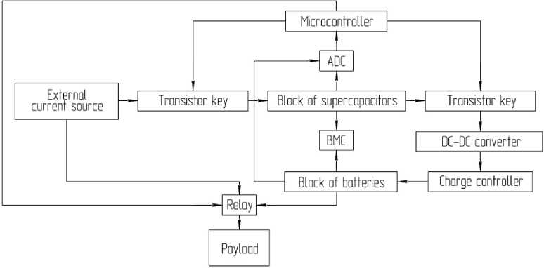
Рис. 1. Структурная схема комбинированного накопителя электроэнергии
Fig. 1. Structure diagram of a combined energy storage еlectrical energy
The principle of operation of the circuit is as follows: charging begins with the accumulation of electricity by a block of series-connected supercapacitors from an external current source to the required voltage, after which the external current source circuit is decommutated from the block of supercapacitors; further, the battery pack is charged from supercapacitors through an intermediate DCDC converter and a charge controller, which is necessary to ensure the best method of battery charging [6; 7]. Since the capacitance of ionistors is much less than batteries, charging is cyclical until the required voltage or charge level is reached on the batteries. The load is powered directly from the battery pack or through an external current source, where a relay is used to switch between two power sources; the state of those is set by the microcontroller. Charging is controlled by transistors operating in the key mode and switching the circuit between the battery, supercapacitor and an external current source. Transistors and relays are controlled by a microcontroller. Analog to Digital Converter (ADC) is used to monitor voltages on one battery and supercapacitor, with the subsequent transfer of information to the microcontroller.
Maintaining operability and ensuring the maximum service life of a block of series-connected drives is possible only if constant monitoring and control of the state of each cell is ensured [8; 9]. To solve this problem, balancing systems are used (Fig. 2) which allow maintaining the required value of voltage and capacitance on individual elements. At the moment, there are two main types of balancing - passive and active, each of which has their own advantages and disadvantages.
The passive variation is distinguished by its simplicity: the discharge of batteries that require balancing is carried out by means of bypass circuits (the mode of supplying the load with mains voltage bypassing the main circuit of the system), providing power dissipation against constant resistance. Such circuits can be located in the battery pack or located in an external board. Almost all excess energy from cells with an increased charge is converted into heat, and this is the main disadvantage of the passive technique, since there is a reduction in battery life without recharging.
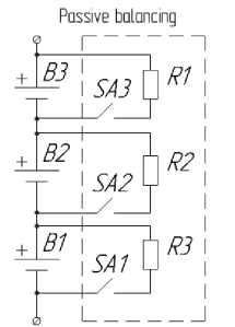
Рис. 2. Пассивная и активная балансировка
Fig. 2. Passive and active balancing
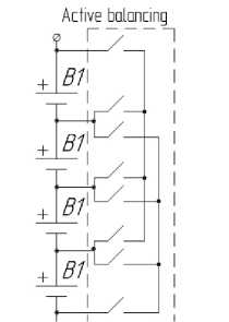
The active method is better in terms of saving the already accumulated energy in the cell. The method consists in transferring energy from batteries with a large charge to less charged batteries, using inductors, transistors, capacitances and DC-DC converters, in which energy losses are negligible. It is appropriate to give preference to this method in cases where there is a need to ensure maximum battery operation time without recharging. The disadvantage of this scheme is its high cost [10; 11].
Mathematical model of combined electrical energy storage
According to the block diagram (Fig. 3), a mathematical (computer) model of a combined drive was assembled in the Simulink environment to assess the possibility of the proposed structure, as well as for analysis and research under various operating modes [12].
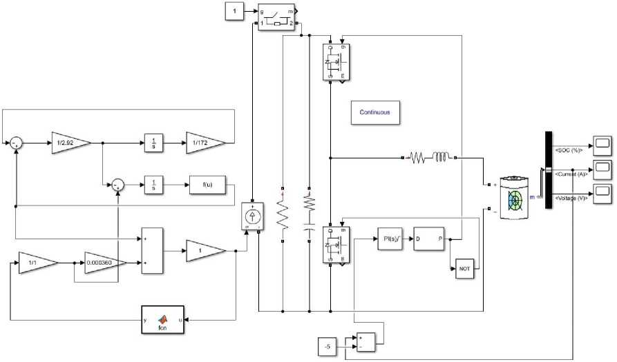
Рис. 3. Математическая модель комбинированного накопителя электроэнергии
Fig. 3. Mathematical model of the combined еlectrical energy storage
The mathematical model of the combined energy storage device includes models of a supercapacitor, a charger, a lithium-ion battery, and a microcontroller that controls the charging of the combined energy storage device.
The supercapacitor model contains two branches, consisting of capacitors and resistors - slow and main, connected in parallel (Fig. 4). Thus, the voltage on them is always the same, and the currents pass between them in proportion to the resistors R 1 , R 2 and R f to take into account losses [13].
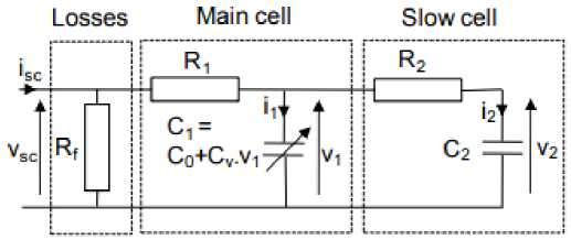
Рис. 4. Двухветочная схема модели суперконденсатора
Fig. 4. Two branches model of a supercapacitor
Fig. 4 v 1 and v 2 show the voltages on the capacitors; C 1 and C 2 are the capacitances of the main and slow capacitors, respectively.
To calculate the components of this model, the characteristics of a real supercapacitor, such as capacitance, voltage, and internal resistance are needed.
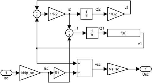
Рис. 5. Математическая модель суперконденсатора
Fig. 5. Mathematical model of a supercapacitor
The input of the mathematical model (Fig. 5) is connected to a programmable block that sets both the current at the input of the supercapacitor and the charging method for various modes. The first element at the input of the supercapacitor is a multiplier. Its value depends on the number of capacitors connected in parallel. The current at the input of the supercapacitor model is shared between all elements. Coefficient formula
K = 1/ N p _ sc , (1)
where N p_sc is the number of cells connected in parallel.
At the output of this element, the current value is obtained in each cell of the supercapacitor block.
In order to obtain the voltage at the output, the current value at the input is multiplied in the main supercapacitor with the resistance R 1 . However, this is just tension at the input of supercapacitors connected in parallel, and for cells connected in series, the output value is multiplied by N s_sc , where
Ns_sc is the number of supercapacitors connected in series. Thus, the supercapacitor voltage is calculated from formula (2):
и =N v =N sc s _sc sc s
sc ( V 1 + R i i sc ) = N s
where v sc and i sc are the voltage and current of each individual supercapacitor; N s_sc – quantity cells connected in series; v 1 , v 2 , i 1 , i 2 are the voltage and current values shown in fig. 5;
i2 = !(v 2 - vl),(3)
R 2
v2 =7" J i2dt = 7] (vl -v2)dt.
C2
The charge that C 2 receives at each moment of time can be obtained by the formula
Q2 =J i2 dt.(5)
The value is integrated with i 2 using the corresponding Simulink element and then multiplied by 1/ C 2 to obtain the value v 2 .
il = isc - i2.
Hence, the current in the slow cell is expressed by the formula dv1 dQ1
il = Ci J= = (C0 + Cvvl) , ’ dt dtdt
Qi = Co vi + - Cvv2.(8)
The voltage across the slow cell is given by
- C o + J C o2 + 2 CQ
0 0
vi =-------------------.
Cv
The implementation of the first branch using the Simulink package is as follows: there is a value i 1 (formula) at the input, after which it is integrated by analogy with the second branch. Having received the value Q 1 at the output, it is fed to the input of the function f(u), which is a formula. All values except Q 1 in this formula are constant for each individual supercapacitor. Thus, having the value v 1 , it seems possible to return to the calculation of the voltage at the output of the supercapacitor bank. v 1 is the voltage value without taking into account the current iteration of the charge.
After adding the voltages v 1 and the charge voltage v sc , the output is the voltage on each system of supercapacitors connected in parallel, which when multiplied by the number of systems, determines the charge value. To limit and control the charge, a function block is used, on which, using the program code, the conditions, voltage limits and input current values set for both charging and discharging the supercapacitor.
Based on the simulation results (Fig. 6), we can conclude that the mathematical model is working. When charging the supercapacitor pack, there is a pause: the battery is not charging. In case of supercapacitors discharging, the battery model is being charged.
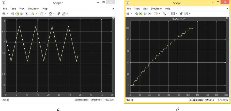
Рис. 6. Циклическая зарядка суперконденсатора от внешнего источника тока с последующей передачей накопленной электроэнергии в аккумулятор ( а ). Циклическая зарядка аккумулятора от суперконденсатора ( б )
Fig. 6. Cyclic charging of the supercapacitor from an external current source, with subsequent transfer of the accumulated еlectrical energy to the battery ( a ).
Cyclic charging of the accumulator from the supercapacitor ( b )
The use of combined energy storage
Currently, small spacecraft (SSC) are rapidly developing, capable of performing various tasks: from educational and research purposes to communications and surveillance. One of the problems that exist in this area is power supply systems - small satellites cannot carry large volume energy storage devices, which leads to to their heavy reliance on constant recharging with solar panels and strict battery economy.
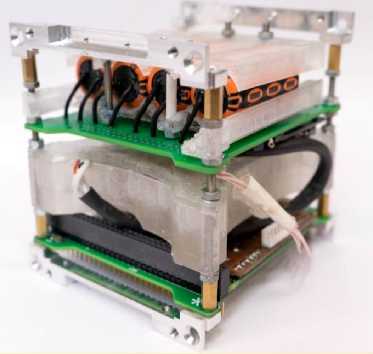
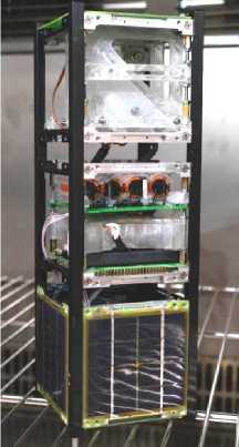
One example of the use of a combined energy storage device is the work performed at BSTU "VOENMEH", where a prototype of a combined energy storage device was designed and developed based on four series-connected supercapacitors and two series-connected lithium polymer batteries (Fig. 7).
As part of the CubeSat satellite prototype for educational purposes, the combined drive is shown in fig. 8. One of the tasks is to experiment the operation of the prototype in real conditions.
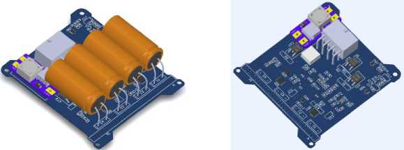
Рис. 7. 3D-модель прототипа печатного узла комбинированного накопителя
Fig. 7. 3D model of a prototype printed circuit board of a combined storage
The developed energy storage device as part of the CubeSat satellite can be charged with low currents from solar panels with subsequent transfer of electricity to batteries to provide power to the load (in the form of servo drives).
б
а
Рис. 8. Печатный узел комбинированного накопителя ( а ); накопитель в составе спутника CubeSat ( б )
Fig. 8. Printed circuit board of the combined storage ( a ); the storage as part of the CubeSat ( b )
The manufactured prototype of the combined energy storage device has the characteristics presented in the table. The product is capable of charging up to 11.2 W and low currents.
Characteristics of the combined energy storage prototype
|
Physical value |
Numerical value |
Measurement unit |
|
Input voltage |
до 11.2 |
V |
|
Input current |
до 3 |
А |
|
Output voltage |
от 7 до 8.4 |
V |
|
Output current |
до 1.5 |
А |
|
Weight |
~320 |
g |
|
Dimensions |
85 x 93 x 50 |
mm |
|
Total capacity |
1500 |
mAh |
As another example of application one more work at BSTU "VOENMEH" can be cited, where as part of the exploratory research, a system was developed to control the shape of a radio-reflective net fabric of a large-sized transformable structure (LTS) (Fig. 9). The actuators included in this system received energy through an open optical channel. When using this method, the charging current was quite small and there was a problem of energy accumulation on the batteries. To solve the described problem, the use of a combined energy storage device was considered, which due to its characteristics was able to be charged from low currents [14; 15].
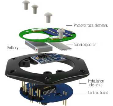
Рис. 9. Применение комбинированного накопителя в КТК
Fig. 9. The use of a combined storage in large-sized transformable constructions
Conclusion
Combined storage devices can find their application as a backup power source in spacecraft, particularly in the field of small spacecraft, where they can be used to charge system batteries from low current sources, for example, with incorrectly oriented solar panels. It is also possible to use largesized transformable structures in shape control systems, where combined storage devices can serve to power control devices, being charged wirelessly from photoconverters.
The authors aim to study the possibilities of charging combined storage devices from low-noise lasers of information transmission systems over an open optical channel.
References Prospects of application of the combined storage space application
- Rentiuk V. [Power supply systems and prospects of using GaN in spacecraft]. Power Electronics. 2019, No. 6, P. 20–26 (In Russ.).
- Korovina N. V., Skundina A. M. Chimicheskie istochniki toka [Chemical current sources: Handbook]. 2003, 704 p.
- Taganova A. A., Bubnov Y. I., Orlov S. B. Germetichnie istochniki toka [Sealed chemical current sources. Elements and accumulators of test and operating equipment], 2005. 264 p. (In Russ.)
- Vinogradov K. N., Shestakov I. Y., Fadeev A. A., Nadaraia C. G. [Application of ionic cells in combined energy storage] Aktualnie problemi aviacii I kosmonavtici 2017, No. 13, P. 373–374 (In Russ.)
- Noskin G. V., Khavanov E. S. Beschastny R. A. [Hybrid electric energy storage device based on lithium-ion batteries and blocks of supercapacitor for power supply systems of returned spacecrafts]. Forestry bulletin. 2019, No. 4, P. 39–48 (In Russ.)
- Tishkov A. I., Shirshov А. D. [Full input power range electricity accumulator]. Patent RF, no. 2018145815, 2019
- Tishkov A. I., Konoplev Y. V., Yuev A. A., Shevtsov I. V. [Development of a combined electric power storage device] Russian Aeronautics. 2019, Vol. 62, No. 2, P. 321–325.
- PowerPump Balancing. Available at: http://www.ti.com/lit/an/slua524b/slua524b.pdf?ts=1606312318354&ref_url=https%253A%252F%252Fwww.google.com%252F.
- Kulova T. L., Nikolaev I. I., Fateyev V. N., Aliev A. Sh. [Modern electrochemical energy storage systems] Kimya Problemleri. 2018, No. 1, P. 9–34 (In Russ.)
- Rykanov A. [Li-ion battery balancing systems]. Power Electronics. 2009, No. 19, P. 52–55.
- Xihua W. The battery charge takes a long time to run and prolongs battery life. 2009. Available at: https://www.compel.ru/wordpress/wp-content/uploads/2009/09/TI_AAJ_1Q2009_3.pdf.
- Kuznetsov V., Pankina O., Machkovskaya N. [Condensers with double electric layer (ionic layer): development and production] Components and Technologies. 2005, No. 50, P. 12–16 (In Russ.).
- Zubieta L. Characterization of Double-Layer Capacitors for Power Electronics Applications, M. A. Sc. thesis, Dep. Of Elect. and Comput. Eng., University of Toronto, Toronto, Ont., Canada, 1997, 173 p.
- Kochin L. B., Krylova M. A., Khromikhin D. A., Shirshov A. D., Popylev V. G. [Energy and Information Transfer via Optical Channel for Shape Control of Space Antenna]. Materiali XXI Megdunarodnoi nauchno-practicheskoi konferencii pamyati generalnogo konstructora racetno-technicheskih system academika M. F. Reshetneva [XXI Reshetnev Readings named after general designer of space system M. F. Reshetnev], Krasnoyarsk, 2017, P. 129–130 (In Russ.).
- Matveev S. A., Strakhov S. Y. Khromikhin D. A. et al. [Organization of energy-information exchange between shape control devices of transformed antenna with application of fiber-optic technologies]. Optical Journal. 2016, Vol. 83, No. 11, P. 73–78 (In Russ.).
