QSWMCA - Quality of Service in Wireless Mesh Networks by Configuration Arguments

Author: N.Kannaiya Raja, R. Saritha, A.Senthamaraiselvan, K. Arulanandam
Journal: International Journal of Computer Network and Information Security(IJCNIS) @ijcnis
Article in issue: 6 vol.4, 2012.
Free access
In this paper, we present a Quality of Experience (QoE) based upon the analyze the key Quality of Service (QoS) parameters such as delay, jitter, throughput, packet loss, packet inspection in the mesh networks which executing the better approach for reconfiguration wireless mesh networks in the routing protocol. In this system evaluates the actual QoE level for each mesh node taking into an account to calculate QoS parameters and then this response as reducing the node broadcasting rate and investigating the problems of selecting in which links would be established that all nodes are connected for cost of constructions are minimized.
QoE, Wireless Mesh Networks, channel selection, topology control, automatic configuration, QoS
Short address: https://sciup.org/15011088
IDR: 15011088
Text of the scientific article QSWMCA - Quality of Service in Wireless Mesh Networks by Configuration Arguments
Published Online June 2012 in MECS and Computer Science
Nowadays for the Internet users, Wireless mesh networks (WMNs) have emerged as a popular alternative to provide last-mile connectivity. Self-configuration networks are the networks where participating nodes automatically establish and maintain connectivity amongst them. WMNs are dynamically self-organizing and self-configuring. These networks are robust and have low up-front and network maintenance costs. A WMN with extended connectivity may be thought as a multihop mobile ad-hoc network (MANET). They provide a cheaper alternative last mile connectivity than ADSL or Cable networks and have created academic and industrial deployments. As deployments of WMNs continue to grow and expected these networks to have the ability to support the new generation of streaming-media applications, such as voice over IP (VoIP) and video on-demand (VOD) [1]. These applications require quality of service (QoS) guarantees in terms of minimum bandwidth and maximum end-to-end delay. Most existing work on wireless mesh networks rely on adapting protocols originally designed for mobile ad hoc networks, and offer little support for QoS. In this paper, we propose a routing protocol for wireless mesh networks that provides parameter QoS to applications based on metrics of minimum bandwidth (Bmin ) and maximum end-to-end delay (Tmax ).
We have been experiencing a rapid growth of interest in WMNs for the last few years. The wireless mesh networks, comprised of nodes with multiple radio interfaces routing the packets are a promising technology, for example for broadband residential internet access or to provide connectivity to temporal events. In order to simplify network deployment, the auto-configuration procedures providing automatic network start-up with minimum manual configuration of the nodes are increasingly important. To maximize the utilization of radio resources the efficient algorithms to select optimal channel to the current radio propagation condition are required. For creation of QOS in a mesh network, the algorithms to manage quality of service resource reservation allows greater increase of the usability of the network. All these algorithms have been developed within the EU-MESH project [2], which aims to create novel configuration procedures, resource management, QoS routing, and mobility support algorithms that achieve efficient usage of both the wireless spectrum and fixed broadband access lines. Wireless mesh networks will support low operation and management costs, leading to increased competitiveness of existing providers, but also lowering the entrance barrier for small and medium enterprises to enter the high growth potential mobile broadband access market. Within this article we present a framework in order to provide an efficient auto configured mesh network able to provide maximum quality of service to the connected users. This work has been part of the EU-Mesh project. EU-MESH’s network architecture view is shown in Figure 1 [2]. Mesh Routers (MRs) are devices with multiple radio interfaces, operating on different channels and with advanced power control capabilities.
In this paper, we have handled the problem of configuration arguments such as delay, jitter, throughput and packet loss which automatically optimizing performance of wireless mesh network. Section II describes about wireless mesh networks. We evaluate the architecture framework in Section III. This section also briefly explains some modules and the results are given in the following tables. Finally Section IV concludes the paper.
-
II. RELATED WORK
Wireless networks have been an active area of research interest and a significant work has been done on routing in wireless networks. But there has been a relatively less focus on providing “strong” QoS guarantees for WMNs. Most of the existing work is either focused on MANETs or WMNs which have multiple radios. A review of relevant literature shows that various approaches have been taken to provide QoS guarantees. Some researchers advocate for a stateless approach [3], while others have advocated maintaining state at intermediate nodes [4–6]. This paper proposes QoS based on the parameters created and implement QOS after longtime used. Moving on to the stateful approaches in a Distributed QoS Routing Scheme where the path is computed by the exchange of control messages, and the state information kept at each node is collectively used to find a path. WMR [5] is another stateful protocol that has been proposed to provide QoS enabled routing in WMNs and is the result of modifying its MANET counterpart, upon detection of a QoS violation, switch channels to connect to another AP. Another approach [7] proposes clustering of end hosts and use of orthogonal channels to reduce the effect of interference. A very different method [7] suggests the use of a statistical mechanical technique which is a new QoS routing protocol for wireless mesh networks. They use delay and bandwidth as the QoS parameters given. There has been some work in designing solutions for providing QoS enabled routing for WMNs, none of these protocols deliver “strong” QoS guarantees in terms of latency or throughput metrics.
Our work, QSWMCA, is a tasteful approach that performs On-demand route discovery and selection using multiple metrics like bandwidth, delay, jitter, packet loss and packet inspection while providing “strong” QoS guarantees. Even though the problem of providing QoS guarantees based on multiple constraints has been shown to be NP Complete [7], it is also known that with suitable heuristics, a multiconstrained QoS routing algorithm can work in polynomial time [8]. QSWMCA differs from the work described above in various aspects. Firstly, our network uses single radios throughout (although the Mesh Routers use multiple radios, one radio is used to communicate with the clients while the other is used to communicate with other MRs). Although recent research [9, 10] propose the use of multiple radios, we go for single radios for simplicity, energy efficiency, and lower cost. Secondly, QSWMCA is a reactive protocol that maintains “soft” state of all the nodes in the network. Thirdly, QSWMCA uses a novel DUMMY-RREP phase to accurately predict the delay that will be experienced by the flows in the network. Finally, QSWMCA uses a concept of the Robustness of the routes. The robustness of the nodes Mobile Netw Appl (2007) 12:358–369 are calculated by using the HELLO messages used to exchange the information about the reservations at each node. The robustness metric not only allows rejection of transient routes and working around the fluctuating neighbor problem, but it also equips the protocol with the inherent ability to tackle a type of “Selfish” behavior referred in literature as “Free-riding’ [11].
-
III. ARCHITECTURE FRAMEWORK
In this section we will present a general framework for providing automatically configured, optimized and QoS-aware wireless mesh networks. The framework is composed of several key mechanisms that could work as standalone in order to provide their basic functionality to a network, but when they interlock they achieve maximum performance. These mechanisms can be grouped into three general procedures that are the following:
-
• Auto configuration,
-
• Channel assignment
-
• QoS enforcement.
The general framework, the mechanisms that consist it and their interconnections are depicted in Figure 1. As one can notice, in this framework we are considering a centralized architecture, since all the decisions are being taken in the Network Manager, which is a central network node. This node communicates with the mesh routers and they exchange the needed information to execute the mechanisms and take decisions for the optimization of the mesh network performance. When the network is initialized, the network manager should perform a network discovery in order to identify the nodes that belong to the network and assign IP addresses to them (using our modified version of. DHCP that we will present in section II-A) in order to be able to communicate and exchange commands (as a first step) and to exchange data (as a second step after the network configuration and the session setup from the users).
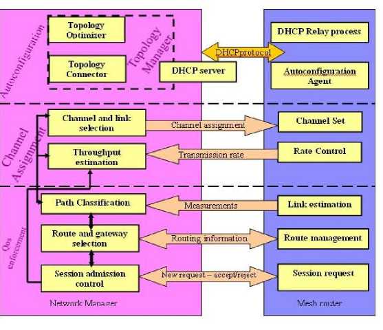
Fig 1. Architecture Framework
The Topology manager collects the (periodically transmitted) data from the routers about active connections, monitors the WIFI associations, ARP tables etc., And collects the statistics per connection (like the RSSI or data rate). All this information is gathered at the Network Manager. The mesh router transmits only information about active links and the link candidates that it is able to sense. When the Network Manager requests scanning information, the mesh routers switch some interfaces to scanning. The unused interfaces can scan without problems, but when an interface is used (i.e. To create a link) we can apply an algorithm which tries to establish an alternative path, and when it succeeds, it configures the interface and starts the scanning and sends the information to the Network Manager. After setting up the topology and assigning IP addresses to the mesh routers, the channel assignment algorithm is executed in order to establish links between the nodes and assign channels to the wireless interfaces. Channel assignment takes as input the topology from the auto configuration mechanism and has a goal to optimize the topology of the mesh network according to some utility functions that will be described in section II-B. When the mechanism is executed, the Network Manager communicates with the mesh nodes in order to get transmission rate information from the rate control module and when it establishes a link it sends commands to set the channel in the respective interfaces. The channel assignment at the Network Manager reads the data about current links and link candidates runs the optimization function and provides the new optimized topology. This goes as input to the application algorithm, which starts by ordering the nodes in topology aware order starting from the most distant to the nearest to the backhaul. Then the new configuration is sent to the devices, starting from the most distant ones. This assures that we are able to send the new configuration to all of the devices, as the new configuration probably breaks the existing communications. The channel assignment algorithm may also work in incremental mode; in this case the optimization is run in response to an auto configuration request. Here, when there is a new addition to the network (a new node or a new set of nodes) the auto configuration algorithm finds the link with the highest RSSI connects there with one interface and tries to get the parameters by DHCP that assigns IP addresses to the new node(s). At the next step, the topology optimization triggers the start of the channel assignment algorithm with the limitation that it shall not change any of the existing links, except the one going to the new node(s). After the completion of the channel assignment algorithm, the QoS enforcement mechanism is applied, which consists of several modules (as depicted in Figure 1). For all users, it should find the best route to serve them with the needed QoS, so it applies the routing algorithm that simultaneously selects routes and gateway for the mesh node. The Network Manager takes measurements of the links and makes a classification of the available paths, which is given as input to the module that performs the route and gateway selection algorithm. This is also triggered every time there is a new session request from a user that is being forwarded from the mesh router to the
Network Manager in order to perform the admission control and ensure the QoS of ongoing users. In the following paragraphs we will analyze in more details the techniques we use for auto configuration, channel assignment and QoS enforcement.
-
A. Auto configuration
The auto configuration component in a wireless mesh network provides a method for automatic mesh start-up, joining a node into an existing mesh network and automatic repair of temporary connectivity outage. The main objective of this component is to simplify the node configuration process as much as possible. The auto configuration provides our network with methods to set up transmission parameters, while joining a node into an operational mesh network, to merge two disjoint networks, and to sustain the network transmission in case of link or node failure. The main goal is to automatically create a fully operational network without the requirement of any manual configuration of the mesh nodes. The Layer 3 mesh networks route the packets at the IP layer and may support multiple types of radio technology like e.g. WiMAX and WiFi. They are able to forward routing information through multiple interfaces and provide better integration with wired networks. For such a network to be operational, a unique IP address needs to be assigned to each network interface, together with the establishment of the layer 2 connectivity, by the correct configuration of channels and ESSIDs. There are two IP address auto-configuration mechanisms in frequent use: DHCP and Zeroconf. Unfortunately, in their basic form they are not directly applicable in multi-hop wireless networks because of such a network setup the problem is either reachability or address uniqueness or both. Auto- configuration schemes for MANET have also been proposed. Most of them are based on Duplicate Address Detection and cannot be used in a network that is not a single broadcast domain, as is the case of multiple radio wireless mesh network. We have developed novel auto configuration procedures, based on extensions to DHCP server and client implementations and BOOTP relays, to support both automatic and predefined configurations of multiple radio interfaces in mesh nodes. The underlying auto configuration method is applicable to networks with technology heterogeneity and it is independent of the routing protocol in use. To optimize the routing it can automatically partition the IP address space into subnets. The DHCP server may be preconfigured by a network operator (possibly integrated within the network management system) or can be automatically started on one of the mesh nodes, to provide a fully automatic network setup. The DHCP protocol was selected because it is relatively lightweight, easy to deploy and requires only minor changes to support wireless mesh auto configuration. The IP address configuration of nodes having direct communication with the DHCP server (within 1 hop distance) is obtained by direct exchange of DHCP packets. For the auto configuration of further nodes, the BOOTP relays are used to forward DHCP requests to the server. The relays are working on all nodes that take part in packet forwarding. Each relay learns the address of the DHCP server as the address of the server that provided IP addresses for the relay node. The mesh node starts by scanning for a compatible network. After the scanning procedure finishes, the node should try to connect to any of the discovered networks or simply try to connect to any ESSID that appears to be part of a mesh network. The node starts the joining procedure start from the networks with the strongest signal level and with only one radio interface turned on. After establishing the link with the first interface the node sends the request for IP address, channel assignment and other radio parameters for every of its mesh interfaces.
The DHCP server was extended by a topology manager module and assigned the radio parameters, defining the topology of the network. New fields are added to DHCP packets as the vendor specific options. The DHCP server organizes the topology of the network by assigning IP subnets, which an interface should join. While it provides the IP addresses, it can also arrange which nodes should communicate with which directly. A distinct subnet is created for each of the cliques. For 802.11 networks it also provides the SSID and the channel, dividing the mesh network into cliques. It works together with the channel assignment, described in the following section, to provide the optimized parameters for the mesh nodes. The Network Manager also keeps track about the current state of all nodes in the mesh network they periodically send the DHCP Renew messages. There is a mechanism for automatic server role takeover by another mesh node in case of DHCP server failure, described in details in [12]. The auto configuration procedure introduces additional overhead into the network load, but the proposed scheme requires only the transmission of 4 packets per each interface per beat-up of a node, and 2 packets per interface to periodically update the state of the DHCP server and topology manager. In typical mesh networks consisted of tens of nodes this will introduce additional load less than 0.1% of the link throughput - more detailed analysis is given in [12].
-
B. The QoE Based Approach
The goal of the proposed mechanism is to monitor the performance level of a mesh network in order to ensure a stable and a proper QoE level for each mesh node. Objective QoS parameters are measured, and then mapped to the user-perceived QoE, which is expressed through the Mean Opinion Score (MOS). Performance and service quality problems should be detected as quickly as possible by the approach, and a precise reaction should be provided to maintain a high QoS level and a good quality level for the services.
Every relay mesh node is equipped with monitoring capacities, which evaluate the current network conditions, and provides a response accordingly. The approach provides QoS support at MAC Layer by using NAMAN (Novel Approach to Mobile Ad-hoc Network) Layer 2 routing functionality. NAMAN protocol operates entirely on ISO/OSI Layer 2, so not only the routing information is transported using raw Ethernet frames, but also the data traffic is handled by NAMAN. NAMAN encapsulates and forwards all data traffic until it reaches the destination, thus emulating a virtual network switch of all mesh nodes. Hence, all nodes seem to be linked local and not aware of the network's topology. The NAMAN algorithm [9] is detailed as follows. Each node (also referenced as Originator) periodically broadcasts hello messages, known as Originator Messages (OGMs), to tell its neighbors about its existence. An OGM owns at least an Originator address, a Source address, a Time To Live (TTL), and a unique Sequence Number value. As a neighbor receives an OGM, it modifies the Source address to its own address and rebroadcast this OGM in accordance with NAMAN forwarding rules to tell its neighboring nodes about the existence of the node that originated the OGM, and so on and so forth. Hence, the mesh network is flooded with OGMs until every node has received it at least once, or until lost because of communication links packet loss, or until their TTL value has expired. The Sequence Number value of the OGM is utilized to verify how fresh the message is, i.e., To discern between new OGMs and duplicated OGMs in order to guarantee that each OGM is only counted once. The amount of OGMs, i.e., The total number of Sequence Numbers, received from an Originator via each neighboring node is utilized to calculate the route quality, i.e., The Transmission Quality (TQ). Thus, NAMAN chooses as next-hop to the Originator the neighboring node from which it has received the highest amount of OGMs from that Originator within a sliding window. Basically, the proposed approach consists of two modules, the Traffic Monitoring Module that analyzes the network performance status of the node, and the Routing Control Module that offers different possibilities to influence on the traffic that goes through the node in order to provide appropriate QoS. These two components must communicate with each other in the node for QoS/QoE information exchange. Furthermore, all the Routing Control Modules throughout the network should be able to exchange QoE and performance information in a distributed way. Figure 2 shows the general structure of the proposed approach. The main part is formed by the NAMAN Layer 2 protocol. Running NAMAN on every node enables all the nodes to connect to each other and to form a mesh cloud. The Traffic Monitoring Module is implemented as a hybrid probe in each node, which passively captures packets passing through to the NAMAN interface and actively injects NAMAN traffic in the network, when necessary, to collect measurements such as packet loss, and round trip time. In addition, the module is executed independently of the network layer (ex.: IPv4, IPv6, and DHCP) and the transporting protocol.
The Routing Control Module is implemented as an extension to NAMAN protocol. It can make use of NAMAN OGMs or generate specific messages to allow communication between different Routing Control Modules . The Routing Control Module and Traffic
Monitoring Module are connected to each other via communication sockets. Sections B.1 and B.2 explain these two modules in more detail. They got
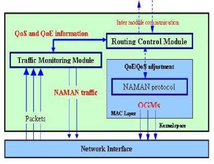
Fig.2. Scheme for QoE/QoS control
-
B.1 Traffic Monitoring Module
The Traffic Monitoring Module is an active and passive network-monitoring tool that is customized for a NAMAN mesh network to monitor QoS parameters from the mesh network traffic. The Traffic Monitoring Module obtains some basic information about a certain packet stream flow that it intercepts and analyzes. Table 1 illustrates the explicit information provided by the Traffic Monitoring Module that is extracted from NAMAN packets and from the node’s routing table. For instance, the node receives an OGM from its neighbor Fe: Fe: 00:00:02:01 (Source address), which was originated by node Fe: Fe: 00:00:01:01 (Originator address) with a unique Sequence Number value. According to the node’s routing table its neighbor Fe: Fe: 00:00:02:01 is the current best ranking neighbor towards the Originator. The routing table also provides a “Potential Next Hop” towards the Originator.
Table 1. Explicit information extracted from NAMAN packets and the routing table
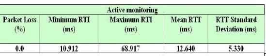
Active Approach. Table 2 presents the statistical information obtained from the active monitoring mechanism. The Round Trip Time (RTT) is the length of time it takes for a packet to be sent plus the length of time it takes for an acknowledgment of that packet to be received.
Table 2. Statistical information obtained from the active monitoring mechanism
The active monitoring approach is applied to obtain the Packet Loss , the Minimum RTT (the shortest RTT), the Maximum RTT (the long RTT), the Mean RTT (the average of measured RTTs), and the RTT Standard Deviation (an indication of how regular or varied the RTTs were). For that, NAMAN Advanced Control and Management tool ( nactl ) is employed [10].The reason to use NAMAN nactl tool is sinice NAMAN operates on Layer 2, thus all nodes participating in the virtual switch are completely transparent for all protocols above Layer 2. Therefore, the most common diagnostic tools do not work as expected in a NAMAN mesh network. The nactl ping diagnostic tool is a useful way to determine if a network connection is of sufficient quality, for example, to carry out a VoIP call without voice quality degradation. For that, the nactl ping tool injects custom ICMP echo request packets into the data flow demanding an immediate response. Then it measures the time it takes for the response to be received. From this, the RTT is calculated. If a response is not detected, then a lost packet is recorded. Note that absolute value of RTT is of less importance since it does not matter at all to voice quality if the an RTT is 1ms or 100ms, what matters for VoIP calls are the following indicators : - If the Mean RTT is less than 150ms, then the latency itself will not be an issue to users. VoIP calls can still be carried on networks with RTTs as high as 500ms and above (satellite network frequently have RTTs higher than 700ms) but the delay is noticeable to callers. - If the Packet Loss is less than 2%, then the voice quality is not affected. In fact, Packet Loss should be close to 0%, but voice quality degradation will only become an issue as Packet Loss goes beyond 2%. -If the RTT Standard Deviation is less than 10ms, then the voice quality is not deteriorated. The main problem with networks carrying voice is jitter [12], the variability in packet latency times. A network with constant latency has no variation, and consequently no jitter. If RTTs vary abruptly then voice quality will suffer from jitter. If RTT Standard Deviation goes beyond 20ms one will start to have problems with voice traffic because of jitter.
-
• If the difference between the Minimum RTT and Maximum RTT values is less than 20ms then jitter is not a problem. If it is above 20ms, then a more detailed analysis of the responses is required to determine if the Maximum RTT is an isolated anomaly or an indication of significant jitter. Frequent variation in the RTT values over a range greater than 20ms indicates jitter issues and voice quality problems. The equations to calculate the RTT statistical information are given below.
-
• For a packed Ƥ i that is generated by nactl tool, the RTT is defined as:
RTT i = te pi - ts pi (1)
where ts pi is the start time, i.e., The time packet Ƥ i is sent to the destination, and tepi is the end time, i.e., The time packet Ƥ i is received back to the sender.
-
• The mean RTT is given by:
1 ∑RTT i
RTT = n i=1 (2)
Where n is the number of measured RTTs for n packets.
-
• The RTT Standard Deviation (or jitter) is calculated as:
RTTSD = 1 ∑RTT2 i – RTT2 (3)
n
-
• The Packet Loss is calculated as:
P Loss
= 1 - n N
where N is the total number of packets injected by nactl tool.
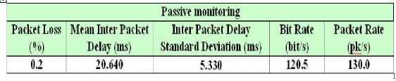
Passive Approach. Table 3 shows the statistical information that can be obtained by passive monitoring, which simply observes the packets passing through the NAMAN node interface. The Packet Loss , the Mean Inter Packet Delay , the Inter Packet Delay Standard Deviation , the Bit Rate , and the Packet Rate can be obtained.
Table 3. Statistical information obtained from the passive monitoring mechanism
For every NAMAN packet pkti that traverses that node the following implicit and explicit information can obtained:
-
- seqi, that is the unique sequence number of pkti generated by Originator O i , for
i = {0, …, n} and j = {0, …, m}.
-
- ti, the absolute arrival time of pkti.
-
- ∆t i = t i – t i-1 , the relative arrival time of pkt i compared to pkt i-1 expressed in seconds,
For 0< i ≤ n.
-
- len i , the total length of pkt i in bytes.
Using these definitions, the statistical information can be obtained as follows.
The Mean Inter Packet Delay is defined as:
MIPD = ∆t =
Where n is the Originator O i
n n ∑ ∆ti
N i=1
number of the packets analyzed for
-
• The Inter Packet Delay Standard Deviation, i.e.,
The jitter, is calculated as:
1 n
IPDSD = n ∑ ∆ t i 2 - ∆ t 2 (6)
i=1
-
• The Packet Loss is defined as : (n+1)
PKT Loss = 1 – (7)
Seq n – seq 0
where (n+1) is the number ofo the captured packets, seq n is the maximum sequence number received from Originator O i , and seq 0 is the minimum sequence number received from Originator O i .
-
• The Bit Rate in kbit/sec(kbps) is defined as:
BR = ∑ leni tn - t0
-
• While the Packet Rate in pkts/s is defined as:
PKT Rate = (n+ 1) t n - t 0 (9)
-
B.2 Routing Control Module
The key part of the proposed approach is the Routing Control Module. It is in charge of evaluating whether the actual network situation is acceptable according to the performance measurements supplied by the Traffic Monitoring Module and if this is not the case, it must decide how to react to the traffic QoS problems. To perform this task, certain thresholds are required.
-
C. Threshold Mechanism
Monitoring of the services alone is not enough to provide QoS/QoE enhancement. It is also necessary a mechanism that evaluates the monitored information and responds in the case of possible performance quality decrease. To perform this task, a threshold mechanism is necessary which indicates a good, medium, or the bad service quality level.
Moreover, key parameters have to be defined in order to establish the thresholds and attribute correct quality levels to them. The key parameters selected to evaluate the QoS and QoS impairment are the previous ones introduced to the active and passive approa ches:
-
- Active approach: the Mean RTT – RTT (latency), the RTT Standard Deviation – RTTSD (jitter), and the Packet Loss – P Loss.
-
- Passive approach: the Mean Inter Packet Delay – MIPD (latency), the Inter Packet Delay Standard Deviation – IPSD (jitter), and the Packet Loss - PKT LOSS. .
In this work, thresholds are defined to evaluate the QoS level, which arebasedd on key performance parameters, and should be configured according to each service. Each NAMAN packet transporting data for a specific service can be configured with 12 threshold values, which 6 for the active approach and 6 for the passive approach, as shown in Table 4. The thresholds values for the active approach take into account a VoIP service, as explained in Section 3.1. For instance, if 0 < RTT < Th m-g the call service will not be affected, and the output of quality level is certainly a good rating. If Th m-g
≤ RTT ≤Th m-b the delay will notably deteriorate the transmission quality, providing a medium quality level. If RTT > Th m-b the user experience will be practically unacceptable, then providing a bad quality level,
Table 4. Thresholds defined for the key QoS parameters of the active and passive approaches
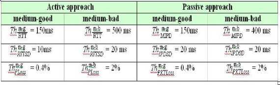
The thresholds of the passive approach are defined in accordance with ITU-T G.114 [13], which recommends that a one-way delay of 400ms should not be exceeded, although highly interactive services such as voice calls and video conferences can be affected by the much lower delay. In addition, if delays are kept below 150ms, most applications, both speech and non-speech, will experience essentially transparent interactivity. The thresholds could become less demanding in the case of a larger number of services running in the network, which demand more bandwidth. Alternatively, they can be more claiming in an empty network, which means more bandwidth resource is available. The threshold adaptation process is based on the defined Bit Rate and Packet Rate values. Therefore, the thresholds can be adapted to different network situations. Moreover, they could assume dynamic values according to each type of service and taking into consideration the network load. The monitored information calculated by the Traffic
Monitoring Module is available to the Routing Control Module at any time. More precisely, the statistical information is computed and saved internally for the last captured packets (for the passive approach) or for the last injected packets (for the active approach). Thus, at the moment the Routing Control Module makes a request, the calculated statistical information (the key QoS parameters) is instantly provided to it. In the active approach, the key parameters are calculated for generating packets at every second. These measurements provide an indication of the network quality at a single point in time. That frequency can be configured by the user to provide more accurate measurements of the network at more regular times. In the passive approach, the key parameters are calculated for newer received packets. This value can also be configured, so that the key parameters can be calculated using more fresh packets. Then, more importance has been given to recently received packets because they can provide a more precise indication of the current network situation.
Afterwards, the calculated key parameters are compared to the thresholds, which are in turn mapped to the QoE expressed as MOS.
In particular, we use the Mean Opinion Score (MOS) to represent the QoE of the VoIP service. In this approach, PESQ method is applied to compare an original audio file with the “received” audio file, which supposes suffered some deterioration in its route due to packet loss or other impairment factors. The PESQ algorithm provides raw scores in the range 0.5 – 4.5, which represent a prediction of the perceived quality that would be given to the received audio by real users in a subjective listening test. The resulting PESQ value is then mapped into a MOS objective listening quality value in the range 1 – 4.5 according to the mapping function in ITU-T P.862.1. The MOS values can assume the following interpretation: (1) bad; (2) poor; (3) fair; (4) good; (5) excellent. At work [15], an exponential relation is established between the MOS and an impairment factor (QoS parameter) such as jitter, or packet loss, for VoIP services. The authors apply the PESQ method and the MOS mapping function respectively using audio files degraded by packet loss ratios along with the reference audio files. The following exponential function is retrieved from the obtained MOS values and the packet loss ratios used in the experiments.
QoE ≅ MOS = 2.866. e-26.335. PLoss + 1.122
We can use the Equation (10) to calculate the MOS values taking into the account the thresholds defined for Packet Loss P Loss. Table 5 illustrates the calculated MOS thresholds representing the QoE level for Packet Loss Threshold – Th p, which are mapped to the VoIP service quality level.
Table 5. MOS values for packet loss representing the QoE mapped to the service quality level
|
Quality level |
MOS (1-4.5) |
El48s(%) |
|
|
good| |
4.0>MOS>3.7 |
0.4 |
° 5 0-4 |
|
medium |
3.7 > MOS> 2.8 |
— |
04 |
|
bad |
2.8>MOS>1.1 |
2 |
- -Bu»- loo |
We can observe that MOS has a maximum value of 4.0 when P Loss is 0%, i.e., No packet loss is detected and VoIP call has a good quality level. As P Loss reaches critical level of 2%, the MOS value drops to 2.8, then signaling a medium quality level. If P Loss achieves the maximum 100%, MOS has the minimum value of 1.1, meaning that the quality level is bad.
-
D. Traffic Control Mechanism
Quality deterioration can occur for several reasons, for instance, packet loss, jitter, and long end-to-end delays, in particular, for WMNs, a cause to these impairment factors could be the high number of collisions between neighboring nodes. A possible reaction of collisions is reducing the amount of transmitted traffic, which causes interference between neighbor transmissions and congests the links. For example, by increasing the OGM interval ( the time that defines how often the node broadcasts OGMs, e.g., The default value is 1000ms) to a
higher value but still acceptable for a mesh network ( to allow NAMAN to recognize route changes in its near neighborhood), the frequency of possible colliding packets is automatically decreased and the link interference as well.
New fields should be added to NAMAN OGMs, or specific messages should be exchanged between the Routing Control Modules of the affected nodes, in order to inform the disturbed nodes that the key QoS parameters and MOS threshold have been surpassed, and the respective QoE level has been deteriorating.
If the detected Packet Loss PKT Loss is high between neighboring nodes, that means the thresholds Th m-b andTh m-b were exceeded, and also the correspondLionssg MOS thLroessshold was surpassed. Therefore, the Routing Control Module of those nodes can apply the following corrective actions.
-
• Increase the OGM Interval of the nodes. Consequently , the Bit Rate BR and Packet Rate PKT Rate values (bandwidth) will automatically decrease for these nodes, and subsequently. Nonetheless, altering the OGM Interval can have effects on the discovery process of the other nodes in highly mobile scenarios.
-
• Apply a Hop Penalty to the Transmission Quality (TQ) field of each OGM forwarded by the nodes. A high Hop Penalty (the maximum value is 255) will make it more unlikely that other nodes will choose this node as the “Best Next Hop” towards any given destination. Thus, the data traffic will diminish on the node’s interface. As a result, the inter node interference and collisions will be attenuated on the communication links, and Packet Loss PKT Loss should decrease.
-
• Force the nodes to update its routing table to change the actual “Best Next Hop” to the alternative “Potential Next Hop” towards the Originator. That would force the node to redirect the current data traffic to other route via other neighbor, then possibly avoiding collisions and interference with the problematic neighboring node. Hence, the Packet Loss PKT Loss would eventually decrease.
As the delay threshold Th m-g and the jitter threshold Th g have been exceeded, MthIPeD quality level is possibly turned medium. If we are dealing with a bandwidth sensitive service, the QoE must be restored to the Gool level. Thus, we apply a bit rate based approach to overcome that issue. The Routing Control Module of the node will use the calculated Bit Rate BR and Packet Rate PKT Rate as a quality metric to select the best route towards the destination (Originator), i.e., The route that offers the highest throughput. For example in Figure 2 node O 1 will choose O 2 as “Best Next Hop” to node O 3 since this path has the best TQ. Nevertheless, the route that provides the most bandwidth to node O 1 is through neighborO 4.
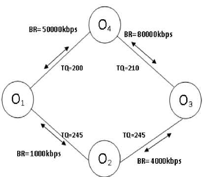
Therefore, the Routing Control Module will update the node’s routing table using as “Best Next Hop” neighbor node O4, which offers the route to the destination with the highest Bit Rate BR. Using this route will certainly decrease the delay MIPD, and the jitter IPDSD values, then improving the quality level.
-
IV. CONCLUSION
In this paper, we have handled the problem of configuration arguments such as delay, jitter, throughput and packet loss which automatically optimizing performance of wireless mesh network. We presented a novel approach for reconfiguring wireless mesh network and optimized Quality of Service aware which calculated by Quality of Service parameters and its created auto configuration scheme for multi-hop and multi-radio wireless mesh networks. We have analyzed also a new utility based framework for the joint channel assignment and topology control that supports different target objectives. Finally, we have presented QoS enforcement component of a mesh network that takes routing and admission control decision.
Experiments show that the higher performance on parameters analyzed with rate based channel assignment scheme. The result also shows that the QoS algorithms utilized on the network resources which quickly find out inefficiency and significant packet losses. The main actual measurements in the network packet loss model and channel assignment procedure in the packet flow.
References QSWMCA - Quality of Service in Wireless Mesh Networks by Configuration Arguments
- Allen M, Zhao BY,"AWolski R (2007) Deploying video-on-demand services on cable networks. In: Proc. Of ICDCS, Toronto, Canada, June 2007
- ICT-215320, EU-MESH (Enhanced, Ubiquitous, and Dependable Broadband Access using MESH Networks), http://www.eu-mesh.eu
- Xue Q, Ganz A (2003) Ad hoc QoS on-demand routing (AQOR) in mobile ad hoc networks. J Parallel Disturb Compute 63:154-165
- Xue Q, Ganz A (2002) QoS routing for mesh-based wireless LANs. Int J Wirel Inf Netw 9:179-190,July
- Chen S, Nahrstedt K (1999) A distributed quality-of-service routing in ad-hoc networks. IEEE JSAC 17 (8): 1488-1505, August
- Wang H, Yow KC (2006) QoS routing in multi-channel multihop wireless networks with infrastructure support. In: InterSense, New York, NY
- LiuL,FengG (2005) Mean field network based QoS routing scheme for wireless mesh networks. In: Proc. Of WiCOM,September
- Kuipers FA, Mieghem PFAV (2005) Conditions that impact the complexity of QoS routing. IEEE/ACM Trans Netw 13 (4): 717-730
- Draves R. Padhte J, Zill B (2004) Routing in multi-radio multi-hop wireless mesh networks. In: Proc. With MobiCom, New York, NY
- Draves R, Padhye J, Zill B (2004) Comparison of routing metrics for static multi-hop wireless networks. In: Proc, of SIGCOMM, Portland, OR
- Mahajan R, et al (2005) Sustaining cooperation in multi-hop wireless networks. In: Proc. Of NSDI
- Grochla K., Buga W., Pacyna P., Dzierzega J., Seman A. "Auto configuration procedures for multi-radio wireless mesh networks based on DHCP protocol", Proc. Of HotMESH09 Workshop, Kos, Greece2009
