Quadrotor control using advanced control techniques

Author: Reham H. Mohammed
Journal: International Journal of Image, Graphics and Signal Processing @ijigsp
Article in issue: 2 vol.11, 2019.
Free access
Control of the quadrotor has been noted for its difficulty as the result of the so-called high maneuverability, exceedingly nonlinear system and strongly coupled multivariable. This work deals with the simulation depend on proposed controllers of a quadrotor that can overcome this difficulty. The quadrotor mathematical model is derived using a Newton-Euler formulation. Three types of controllers are investigated to control and stabilization the position and attitude of quadrotor using feedback linearization. The first controller is Fuzzy-PID, it is considered as a reference benchmark to compare its results with the others two controllers which are PID tuned using GA and ANFIS. The performance of the designed control structure is evaluated through the response and minimizing the error of the position and attitude. Simulation results, shows that position and attitude control using Fuzzy-PID has fast response and better steady state error and RMS error than ANFIS and PID tuned using GA. The all controllers are tested by simulation under the same conditions using SIMULINK under MATLAB2015a.
Quadrotor, Proportional Integral Derivative (PID) controller, Genetic Algorithm (GA), Adaptive Neuro Fuzzy Inference System (ANFIS), Fuzzy-PID controller
Short address: https://sciup.org/15016033
IDR: 15016033 | DOI: 10.5815/ijigsp.2019.02.05
Text of the scientific article Quadrotor control using advanced control techniques
Published Online February 2019 in MECS
Quadrotors are motivating platform for Aerial Robotics research. The thriving interest of aerial robots in military, farming, mining, firefighting and remote sensing etc. has given great impetus to controller research and improvement in this field [1]. The research in controller design of quadrotor is as yet having challenges because: high maneuverability, exceedingly nonlinear system, strongly coupled multivariable and under-actuated condition with 6 DOF and just 4 actuators. [12]. The main objective is concerned with designing a controller for the position and attitude of quadrotor using feedback linearization to meet the requirement of the desired trajectory input with stability, good disturbance rejection, and small tracking error. The solution proposed in this work is to use artificial intelligent controllers such as Fuzzy-PID and a hybrid combined between Fuzzy Inference Systems (FIS) and Neural network controllers to design ANFIS.
-
II. Related Work
There are a several related work of quadrotor control for enhanced performance such as classical linear methodologies utilized for control of quadrotors for example, PID [2, 4, 5, 6], Linear quadratic regulator [5, 6, 7] for ideal control, which at lower speeds give good results, but this methods gave a poor performance at higher speeds as a result of large vibrations of motor controller. In Additionally, numerous advanced control approaches are likewise utilized, for example, nonlinear feedback linearization [9, 10], H-infinity control design, adaptive approach [8], sliding mode control [3] but noticed amount of chattering, Backstepping [3, 6, 9, 11].
Most works have utilized Euler angles for modeling. Additionally it considers the dynamic models of rotors, gears and motors. But most of literature reviews didn't give the acceptable results compared to the required position and attitude where, the target of all controllers' techniques is to stabilize attitude and position of quadrotor with better response.
The main target of this paper is to present intelligent control techniques such as Fuzzy-PID and ANFIS to position and attitude control and stabilization of quadrotor and compared their results with PID tuned using GA. The controller output is straightforwardly fed into the dynamic model without making any mapping in the actuator space. In the simulations presented here, the thrust input cannot be more than double the weight of the matrix; similarly a suitable threshold is additionally put in the torque input. These thresholds have been put to make the control laws as practical as possible.
The organization of this paper: The quadrotor configuration introduced in Section 3. Section 4 introduces the quadrotor modeling. Control strategy is introduced in Sections 5. Simulation results for the three controllers (PID tuned using GA, ANFIS and Fuzzy-PID) are illustrated in Section 6, followed by the concluding remarks in Section 7.
-
III. Quadrotor Configuration
Quadrotor is an Unmanned Aerial Vehicle (UAV) with four rotors. As demonstrated in Fig. 1, the nearby rotors have inverse sense of rotation. This is done to adjust the total angular momentum of the craft; otherwise the UAV will begin rotating around itself. The Quadrotor has 6 DOF but only four actuators (Rotors). Hence, Quadrotors are under actuated. The Rotors produce thrust, torque and drag force and the control input to the system is the angular velocity of the motors. A low level controller balances out the rotational speed of each blade. The Quadrotor can perform Vertical Take Off and Landing (VTOL), hover and make slow precise movements. The four rotors give a higher payload capacity. Quadrotors are moderately less difficult because they don't bring convoluted swash plates and linkages [13].
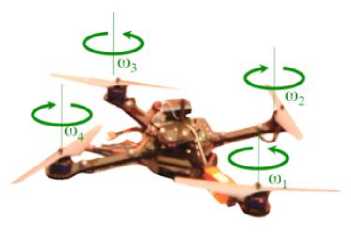
Fig.1. Quadrotor UAV
There are some states that we require in UAV recorded as: Estimation State, calculate position and velocity of quadrotor. Control, drive motors and delivers desired actions in order to navigate to the desired state. Mapping, the quadrotor must have basic ability to map its environment. Planning: Finally, the quadrotor must be able to track the trajectory planning [13].
-
IV. Quadrotor Modeling
-
A. Basic Mechanics
The mechanics of the quadrotor is investigated in this section. The model has been gotten from [13]. The forces following up on the framework are the thrusts Fi from each of the rotor and the force of gravity - mg a 3 . The moments following up on the framework are the moments due to each of the thrust and the drag moment Mi which is created because of the propeller rotation [13].
As appeared in Fig. 2, the Thrust Fi, Drag Moment Mi and Motor Torque Speed Characteristics τ vs. ω. [18].
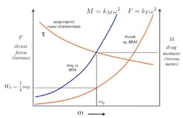
Fig.2. Thrust Fi, Drag Moment Mi and Motor Torque Speed Chacteristics τ vs ω.
-
- Speed of the Motor at Hover Configuration:
-
2
Kf Mq -
Motor Torques and Drag Torque (They have same magnitude however inverse signs):
Mt-Tt- Кмш](2)
Thrust
Ft - KF oF(3)
Resultant Force:
F - F1 + F2 + F3 + F4 - тдаз(4)
Resultant Moment:
M - -1 * F1 + -2 * F2 + Г3 * F3 +r4 * F4 + M1 + M2 + M3 + M4
-
B. Quadrotor Dynamics
The dynamics of a quadrotor by using the Newton-Euler formalism presentenced in this section. The inspiration is gotten from Mellinger work [14].
-
- Newton Euler equation
м3 уса]+|м. 0 / з М1 (6)
where, τ is the net torque, F is the net force acting on the quadrotor, a is the linear acceleration of the center of mass, I3 is a 3 × 3 identity matrix called the moment of inertia, ω is quadrotor velocity angle, v is the linear velocity, m is the mass and α is the acceleration angle.
Rotation Matrix:
|
0- |
" c9 |
0 |
-c
se |
" P |
|
0 |
1 |
sp |
■ e |
|
|
. se |
0 |
cpcd |
■ Ф |
R ^ =
гСфС0 -
S
' I (7)
Thrust Input: u 1 = F 1 + F 2 + F 3 + F 4
φ = Roll, θ = Pitch and ψ=Yaw The equation of Linear Motion is:
Г L(F2-F4) 1
u2 = I L(F3-Ft) | (11)
L m2 +M 4 -M 1 - m3\
mf = | 0 | + R g [
[-mgl L
- F1 + F2+ F3 + F4
The equation of angular Motion is:
I
1'1=1
L(F2
L(F 3
M2 + M 4
-F) -F 1 ) -M 1 -
J-M
Where, I = Moment of inertia, r = [ x y z ] T , [ p q r ] the body angular Velocities , m = the system Mass. The relationship between the rate of change of ( φ , θ and ψ) and body angular velocities is:
V. Control Strategy
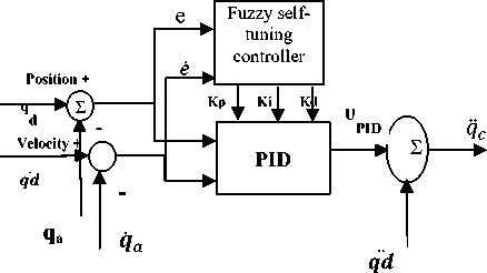
In this paper, intelligent control techniques have been studied and implemented in MATLAB2015a/Simulink. The quadrotor block diagram Control using feedback linearization is appeared in Fig.3. As appeared in the block attitude controller is inner loop while position controller is the outer loop. It is sensible to recognize that the dynamics of the inner loop must be faster than the dynamics of the outer loop. In hover arrangements the dynamics of attitude do not matter much in general, however in situations where the robot needs to make maneuvers, it is basic to have a faster attitude controller. In the following sections, PID tuned using GA Control, Fuzzy-PID and ANFIS are discussed and the results are presented to control the outer loop.
Trajectory planner
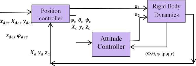
Fig.3. Control Block Diagram.
A. Quadrotor control using PID tuned using GA
The aim of PID is to design a position and attitude controller of a quadrotor by selection of a PID parameters gains k p , k d and k i using genetic algorithm, where GA is an optimization method depend on the mechanisms of natural selection[15].
This control law works well under hover conditions. Linearizing the dynamic model at the hover configuration, where the system model is reduced to:
The reference trajectory is:
f ref = [^ de S y des zdes (p des]T The commanded linear accelerations can be calculated as:
y c = y des + ^ dy ( y des y a ) +
^ py ( y des - y a ) + ^ iy f(ydes - y a ) (15)
m
0=1
(cpse + cescpsp)u 1
(spse - cescpcp')u1
-mg + c(pc6u 1
I
I
I - 'I
= U 2
^c ^des + ^dz(^des kpz(^des - ^a) + ^iz f(^des - ^a)
The commanded roll, pitch and yaw are:
Pc = 1 (Xc suedes') - Ус cos(^des))(17)
9с = 1 (Хс coshes) + ус singes))(18)
^ = ^des(19)
Using equations 14 to 19
Ui = т(д + Zc)
'К
р
ф
(
ф
с
-
Фа)
+
K
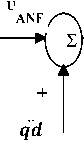
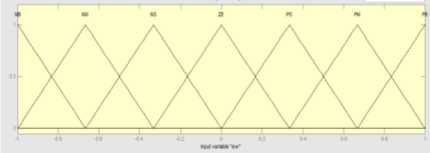
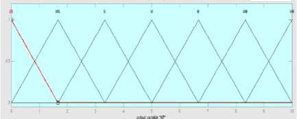
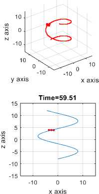
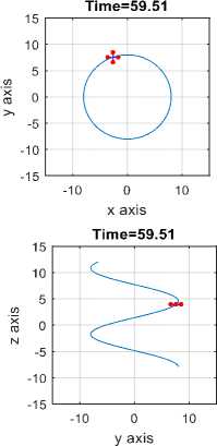
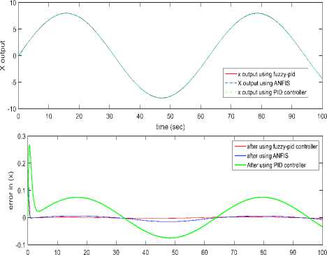
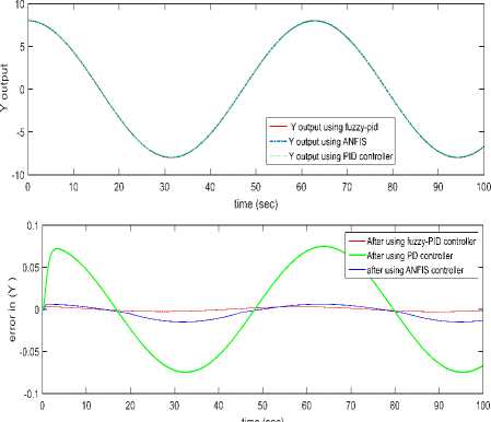
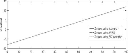
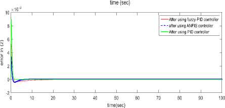
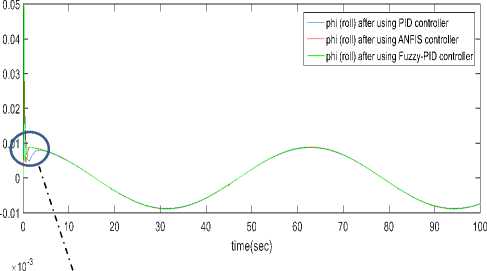
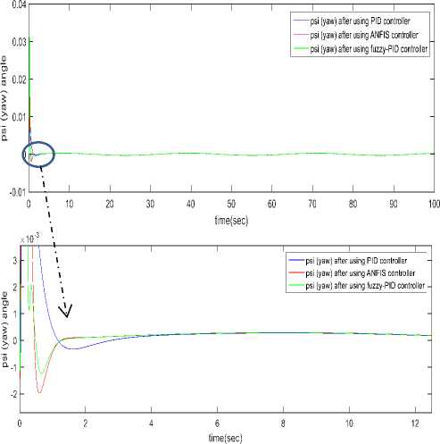
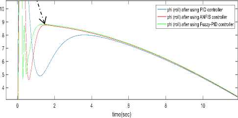
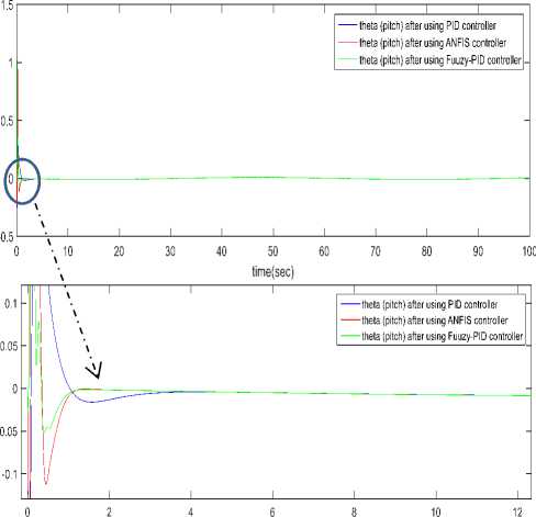
d (Pc - р)" и2=1 Крв(9с - 9а) + Kde(4c - q)(21) .КРф(Фс —^а)+ Kd^(rc- г). Using equation 10 one can get [pc; qc; rc]T . GA applied for tuning PID gains kp, kd and ki for the three position (x, y and z) using Integral Square-Error (ISE) to ensure optimal control performance at nominal operating conditions. The Three gains of PID after tuning for X ( kp1=45.75and kd1=12, ki=33.5), for Y (kp2=51.5 , kd2=56.599, ki=24.5) and for Z (kp3=130.962, kd3=55.25, ki=58.526) then modify this error signal to produce control input for system. The control input then forces the system to produce output as close as possible to the desire position. The solution proposed in this work is to use artificial intelligent such as ANFIS and Fuzzy-PID controllers. B. Quadrotor control using ANFIS 1) Principles of ANFIS The adaptive NF inference system (ANFIS) is one of the proposed controllers which, merges the benefit of neural network and fuzzy logic. Neural network gives connectionist framework and learning capabilities to fuzzy logic and fuzzy logic give neural networks with a structural framework with high-level fuzzy IF-THEN rule of reasoning and thinking. Neural network based on fuzzy logic has learning capability of neural networks to understand the fuzzy logic inference system, have the popularity in the control of nonlinear systems [16, 21]. 2) Structure of Quad rotors Based on ANFIS controller The overall block diagram of the ANFIS control is appeared in Fig.4. The system composed of a forward path in addition to a feedback path. The forward path controller is ANFIS and dynamics model for the quad rotor. The feedback path consists of the actual trajectory (Ха, Ya and Zo) and actual velocity (Xa, Ya and Z а). Fig.4. The block diagram of the proposed ANFIS controller. qc -* The ANFIS controller developed composed of two inputs, position error (e) and velocity error (e). This work considers the ANFIS internal structure for the three positions (X, Y and Z) as the same with first order sugeno model where; contain 4 rules with triangular membership functions (MF). The MFs with product inference rule are utilized at the fuzzification level. Hybrid learning algorithm that combines least square technique with gradient decent strategy is utilized to modify the parameter of MF. The adaptive NF inference framework structure consist of five functional blocks (database, rule base, a decision making unit, a fuzzyfication and a defuzzyfication interface) which are created utilizing five network layers [21]. C. Quadrotor Control using Fuzzy-PID The fuzzy logic programming has been turned out to be broadly utilized as a part of industry. Broad number of researches was progressed using fuzzy logic technique [17]. The Fuzzy-PID controllers are branched into two kinds: the direct action fuzzy control and the fuzzy supervisory control. The direct action kind replaces the PID with a feedback control loop to calculate the action by fuzzy reasoning where, the control actions are estimated directly by means of a fuzzy inference. This kind of fuzzy controller is also called PID-like controllers. Otherwise, the fuzzy supervisory kind tries to provide nonlinear action for the controller output by using fuzzy reasoning where, the gains of PID are tuned depend on a fuzzy inference system rather than the traditional methods. The process design of the fuzzy-PID controller for (X, Y, Z) is characterized as follows [18, 22]: • Define the variables input and output of FLC. There are two inputs of FLC In this work, the error e (t) and it's rate of change of error e(t) and three outputs respectively ( KP ,KI and Kd ) as appeared in Fig.5. Where, qd represent the desired position whether it is X or Y or Z. Fig.5. Fuzzy self-tuning proposed. • The variables of the input and output are Fuzzyfied by defining the fuzzy sets and MFs. Each input variable of fuzzy control has seven fuzzy sets ranging from negative big (NB) to positive big (PB) as appeared in Fig. 6 for the two inputs e and e, and the FLC output has the following MF as appeared in Fig. 7 for the three outputs Kp, Ki , and Kd[22]. Fig.6. The Memberships function of the two inputs (e) and (e). Fig.7. The Memberships functions of the three outputs (Kp1, Ki1, and Kd1). • Find the relation between input and output by design the inference mechanism rule. This work uses Mamdani type (max-min) inference mechanism where, the control rules that used for fuzzy self-tuning of PID controller displayed in tables (1), (2), and (3). • Defuzzify the output by using Center Of Gravity (COG), which, it is the most frequently used method. The control equation is[18]: COG = Sgi^fM ^^^(fi) After self-tuning the control equation of PID controller can be presented as: Upid = Kp2 * e(t) + K21 edt + K2 det) (23) dt Where, the new gains of PID are KP2, KI2, and Kd2 which respectively equals to: Kp2=Kp1 * KP, Ki2=Ki1 * Ki, and Kd2=Kd1*Kd. Where, KP1, Ki1, and Kd1 are the output gains of the fuzzy control that are changing online with the output variable of the system under control. Kp, Ki, and Kd are the initial gain values of the conventional PID [22]. Table 1. Rule bases for calculating gain kp1. e /e NB NS ZE PS PB NB M M M M M NS S S S S S ZE MS MS ZE MS MS PS S S S S S PB M M M M M Table 2. Rule bases for calculating gain ki1. e /e NB NS ZE PS PB NB VB VB VB VB VB NS B B B MB VB ZE ZE ZE MS S S PS B B B MB VB PB VB VB VB VB VB Table 3. Rule bases for calculating gain kd1. e /e NB NS ZE PS PB NB ZE S M MB VB NS S B MB VB VB ZE M MB MB VB VB PS B VB VB VB VB PB VB VB VB VB VB The simulation has been performed for position (X, Y, Z) and attitude (Ф , θ, ψ)control of quadrotor using SIMULINK-MATLAB 2015a by considering the dynamic of the quadrotor from [13] for demonstrating the effectiveness of the suggested Fuzzy-PID position controller than PID tuned by GA and ANFIS where, all controllers tried to track the path of a helical trajectory. The values of the 9 PID parameters obtain by GA with fitness value 0.025411after 260 epochs. ANFIS GUI editor is accessible in the Toolbox of Fuzzy Logic [19]. Utilizing a given input/output data set, the toolbox constructs a fuzzy inference system (FIS) whose parameters of the MF are balanced utilizing either combination of backpropagation algorithm with a least squares type of technique, or a backpropagation algorithm alone. We used A hybrid method which employs for changing the parameters of the MF which consist of backpropagation for the parameters associated with the input MFs, and least squares estimation for the parameters associated with the output MFs [20].This enables the fuzzy logic to learn from the data they are modeling [19]. Time=60.01 Fig.8. The Helical Trajectory after using fuzzy-PID controller. Fig.8 presents the Helical Trajectory that tracked in 3D. This particular screens shot is taken when the Fuzzy-PID Control was utilized with the existence of wind. ANFIS control provides the quadrotor with minimum error between desired and actual position for X, Y, Z respectively with minimum number of iteration= 51 epochs compared with PID controller tuned using GA as shown in Figs. 9,10 and11. time(sec) Fig.9. X-Position and Error in (X) after using the three controllers. Also fuzzy self-tuning PID controller is applied to position and attitude control of the quadrotor. The simulation results as appeared in Figs. 9,10 and 11 prove that using fuzzy self-tuning PID controller give minimum error compared to ANFIS and PID tuned using GA. Fuzzy supervisory attempt to change the parameters of the PID through process operation to enhance the response of the system. The gradient-based optimization process locates search orientation for an objective function minimization. This strategy can be utilized to minimize energy consumption in distributed environmental control systems while keep up a high inhabitant comfort level. Fig.10. Y-Position and Error in (Y) after using the three controllers. Fig.11. Z -Position and Error in (Z) after using the three controllers. Table4 show a comparison between RMS error, steady state error for X, Y and Z for all types of controllers PID tuned by GA, ANFIS and Fuzzy-PID implemented to control the position of quad rotor. Table 4. The comparison results of PID, ANFIS and fuzzy-PID controllers. Contro ller type RMS error S.S. error for X S.S. error for Y S.S. error for Z PID tuned using GA 0.0069 - - 6.217*10- 57 0.03367 0.06726 15 ANFI 0.0055 - - -2.44*10 - S 15 0.007502 0.01316 15 Fuzzy- 0.0008 0.0009 - -4.77*10 - PID 356 089 0.001513 15 From Table4 position control using Fuzzy-PID has better steady state error and RMS error than controlled based on PID tuned using GA and ANFIS. By comparing steady state and RMS error in a system it was found that the Fuzzy-PID’s errors (Steady State error for X position=0.0009089, Y = 0.001513, Z=-4.77*10 -15 and RMS error=0.0008356) than ANFIS’s errors (Steady State error for X=-0.007502, Y=-0.01316 , Z=-2.44*10 -15 and RMS error=0.005515 ) and PID’s errors (Steady State error for X=-0.03367, Y=-0.06726, Z=6.217*10-15 and RMS error=-0.03367). Fuzzy-PID controller has fast response and small errors for the required position of quad rotor. Figs. 9, 10 and 11 give complete comparisons between the three controllers for X, Y and Z errors respectively. Also attitude angles ( roll(Ф) pitch(θ) yaw (ψ) angle ) after using Fuzzy-PID has fast response and small errors for the required orientation than controlled based on PID tuned by GA and ANFIS as shown in Figs. 12, 13 and 14. theta (pitch) angle theta (pitch) angle phi (Roll) angle phi (Roll) angle Fig.14. Yaw (ψ) angle after using the three controllers. Fig.12. Roll (Ф) angle after using the three controllers. time(sec) Fig.13. Pitch (θ) angle after using the three controllers. As appeared in results of Fuzzy-PID controller compared with PID tuned using GA and ANFIS it was observed that By comparing steady state and RMS error the position control of the X, Y and Z controlled using Fuzzy-PID has meet the requirement of the desired trajectory input with stability, good disturbance rejection, and small tracking error better performance than controlled using PID tuned using GA and ANFIS. The responses had showed to us that the system designed based on Fuzzy-PID controller has much faster response than using the other controllers PID tuned using GA and ANFIS for the position and attitude angle. In this work, PID Tuned using GA, Fuzzy-PID and ANFIS controllers have been used to position and attitude control of quadrotor to achieve the required position with fast response and minimum error. As appeared in results of Fuzzy-PID controller compared with PID tuned using GA and ANFIS it was concluded that: • By comparing steady state and RMS error the position control of the X, Y and Z controlled using Fuzzy-PID has better performance, steady state error and RMS error also meet the requirement of the desired trajectory input with stability than controlled using PID tuned using GA and ANFIS. • The responses had showed to us that the system designed based on Fuzzy-PID controller has much faster response than using the other controllers PID tuned using GA and ANFIS for the position and attitude angle.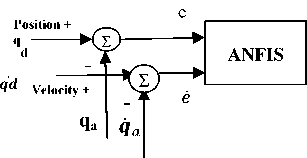
VI. Simulation Results
VII. Conclusion
References Quadrotor control using advanced control techniques
- Kendoul, Farid. "Survey of advances in guidance, navigation, and control of unmanned rotorcraft systems." Journal of Field Robotics 29.2 (2012): 315-378.
- Reizenstein, Axel. "Position and Trajectory Control of a Quadcopter Using PID and LQ Controllers."(2017).
- Subodh Mishra, "Robust Control of Quadrotors." ,Master thesis, Department of Automatic Control and Robotics,(2017).
- Bresciani, T. "Modeling, identification and control of a quadrotor helicopter. Master’s thesis, Department of Automatic control, Lund University, October 2008, p. 170." (2008).
- De Lellis Costa de Oliveira, Marcelo. "Modeling, Identification and Control of a Quadrotor Aircraft." (2011).
- Al-Younes, Younes M., Mohammed A. Al-Jarrah, and Ali A. Jhemi. "Linear vs. nonlinear control techniques for a quadrotor vehicle." Mechatronics and its Applications (ISMA), 2010 7th International Symposium on. IEEE, 2010.
- Minh, Ly Dat, and Cheolkeun Ha. "Modeling and control of quadrotor MAV using vision-based measurement." Strategic Technology (IFOST), 2010 International Forum on. IEEE, 2010.
- Mellinger, Daniel, et al. "Design, modeling, estimation and control for aerial grasping and manipulation." Intelligent Robots and Systems (IROS), 2011 IEEE/RSJ International Conference on. IEEE, 2011.
- Altug, Erdinc, James P. Ostrowski, and Robert Mahony. "Control of a quadrotor helicopter using visual feedback." Robotics and Automation, 2002. Proceedings. ICRA'02. IEEE International Conference on. Vol. 1. IEEE, 2002.
- Mokhtari, Abdellah, et al. "Feedback linearization and linear observer for a quadrotor unmanned aerial vehicle." Advanced Robotics 20.1 (2006): 71-91.
- Madani, Tarek, and Abdelaziz Benallegue. "Control of a quadrotor mini-helicopter via full state backstepping technique." Decision and Control, 2006 45th IEEE Conference on. IEEE, 2006.
- Hou, Hongning, et al. "A simple controller of minisize quad-rotor vehicle." Mechatronics and Automation (ICMA), 2010 International Conference on. IEEE, 2010.
- Mahony, Robert, Vijay Kumar, and Peter Corke. "Multirotor aerial vehicles." IEEE Robotics and Automation magazine 20.32 (2012)
- Mellinger, Daniel Warren. "Trajectory generation and control for quadrotors." (2012).
- Youns, Majed D., Salih M. Attya, and Abdulla I. Abdulla. "Position ControlOf Robot ArmUsing Genetic Algorithm Based PID Controller." AL Rafdain Engineering Journal 21.6 (2013): 19-30.
- Kim, Jaesoo, and Nikola Kasabov. "HyFIS: adaptive neuro-fuzzy inference systems and their application to nonlinear dynamical systems." Neural Networks 12.9 (1999): 1301-1319.
- Pattaradej, Thana, Guanrong Chen, and Pitikhate Sooraksa. "Design and Implementation of Fuzzy P2ID Control of a bicycle robot." Integrated computer-aided engineering 9.4 (2002).
- E, GUV Ravi Kumar, and Mr Ch VN Raja. "Control of 5DOF Robot Arm using Fuzzy Supervisory Contro.l" International Journal of Emerging Trends in Engineering and Development 2.4, (2014).
- Jang, J-SR, and Chuen-Tsai Sun. "Neuro-fuzzy modeling and control." Proceedings of the IEEE 83.3 (1995): 378-406.
- Jang, J-SR. "ANFIS: adaptive-network-based fuzzy inference system." IEEE transactions on systems, man, and cybernetics 23.3 (1993): 665-685.
- Areed, Fayez G., Amira Y. Haikal, and Reham H. Mohammed. "Adaptive neuro-fuzzy control of an induction motor." Ain Shams Engineering Journal 1.1 (2010): 71-78.
- Mohammed, Reham H., Fahmy Bendary, and Kamel Elserafi. "Trajectory tracking control for robot manipulator using fractional order-fuzzy-PID controller." International Journal of Computer Applications 134.15 (2016).;
