Radio Receiver with Internal Compression of Input Signals Using a Dispersive Delay Line with Bandpass Filters

Author: Roman Pantyeyev, Felix Yanovsky, Andriy Mykolushko, Volodymyr Shutko
Journal: International Journal of Image, Graphics and Signal Processing @ijigsp
Article in issue: 6 vol.15, 2023.
Free access
This article proposes a receiving device in which arbitrary input signals are subject to pre-detector processing for the subsequent implementation of the idea of compressing broadband modulated pulses with a matched filter to increase the signal-to-noise ratio and improve resolution. For this purpose, a model of a dispersive delay line is developed based on series-connected high-frequency time delay lines with taps in the form of bandpass filters, and analysis of this model is performed as a part of the radio receiving device with chirp signal compression. The article presents the mathematical description of the processes of formation and compression of chirp signals based on their matched filtering using the developed model and proposes the block diagram of a radio receiving device using the principle of compression of received signals. The proposed model can be implemented in devices for receiving unknown signals, in particular in passive radar. It also can be used for studying signal compression processes based on linear frequency modulation in traditional radar systems.
Compressive receiver, dispersive delay line, signal compression, chirp signal, bandpass filter
Short address: https://sciup.org/15018843
IDR: 15018843 | DOI: 10.5815/ijigsp.2023.06.01
Text of the scientific article Radio Receiver with Internal Compression of Input Signals Using a Dispersive Delay Line with Bandpass Filters
From the point of view of processing received signals, a tangible advantage of active radar is that in this case the shape and spectrum of the sounding waveform are known. This means that the signal scattered by the target at the receiver input should be similar to this sounding waveform despite its changes in the process of scattering on the observation object and all kinds of distortions during the propagation of electromagnetic waves, the influence of interference and noise. This allows receivers to use matched (or quasi-optimal) filters, as well as algorithms for correlation processing of the received mixture, providing the maximum signal-to-noise ratio specifically for the expected reflected signal. This approach is used in primary radar systems of various types, from conventional (incoherent) [1] to coherent-polarimetric [2]. The potential capabilities of the system in terms of resolution and measurement accuracy, as well as the technical complexity of implementing matched filtering in the receiver, depend on the shape of the sounding waveform. At one time, the developers of radar equipment were faced with an unpleasant contradiction: reducing the duration of the sounding pulse in order to increase the range resolution inevitably led to a decrease in the range of the system due to decreasing the energy of the sounding waveform (a short probing impulse). This contradiction was overcome by using wideband probing signals.
Methods of compressing wideband signals with matched filters are well known in the theory and technology of radar. The development of such methods began in the 50s of the last century with the work of Ya.D. Shirman [3] in Ukraine and S.E. Cook [4] in the USA. These developments, of course, were carried out in strict secrecy, the results were obtained completely independently, and fundamentally similar approaches were implemented in significantly different ways [5].
It turned out that by compressing extended probing pulses with a wide spectrum, that is, when t B >>1, where т is the duration of the sounding pulse, and B is its spectrum width, it is possible to overcome the most important problems of radar, namely: increasing range resolution while maintaining a high radar range (target detection range), as well as simultaneously achieving relatively acceptable levels of resolution and accuracy in range and speed, which are limited according to the uncertainty principle in radar [6]. The use of a signal compression system increases the signal-to-noise ratio and increases the sensitivity of the receiver, that means it allows you to detect more distant targets, as well as receive weaker signals.
The formation of broadband probing pulses in a transmitting device is achieved, for example, using intrapulse linear frequency modulation (chirp) [7]. Thus, the signal compression method was developed for active radar and is widely used in systems for various purposes. For example, Fig. 1 illustrates the use of a pulse compression scheme in synthetic aperture radar for viewing the earth's surface, which improves image resolution [8].
This paper discusses the use of a similar approach for primary signal processing in a receiving device, when neither the shape nor the frequency of the received signals is known in advance. Such a receiver is necessary, for example, in monitoring systems or passive radar. The authors carry out preliminary calculations and modeling that confirm the positive technical effect of this approach, which, in particular, provides high frequency monitoring system resolution and frequency measurement accuracy.
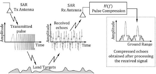
Fig.1. SAR pulse compression circuitry to improve image resolution.
The analysis of the literature showed that our idea of using an artificial compression system in a radio receiver is not pioneering. Along with traditional receivers, such as a superheterodyne receiver and a crystal video receiver that have long been used in monitoring and electronic warfare (EW) systems, a compression receiver is also known [9]. The compression system of such receiver uses dispersive delay line on surface acoustic waves that has significant disadvantages [9]. Therefore, in this work we abandon their use and develop a model of a compression receiver with a dispersive delay line with bandpass filters. It is clear that today it is advisable to talk about digital technologies, with the help of which almost any signal processing procedure can be implemented, including the one proposed in this work. However, this is beyond the scope of the article, although, of course, high-quality digital implementations are possible in principle if the speed of the element base allows. This makes our approach even more general.
Thus, the purpose of this article is to develop a compression receiver with a high-frequency dispersive delay line using high-frequency bandpass filters, as well as analyze and simulate its operation.
2. Concept of a Compressive Receiver
The block diagram of a receiver with signal compression is shown in Fig. 2. This is the simplest configuration to explain the operating principle. The influencing signal is amplified by a broadband high-frequency amplifier (BHFA)
and fed to a mixer (Mix), where a local oscillator voltage is also supplied, being periodically tuned in frequency.
The local oscillator frequency is changed using a tuning circuit, which also controls the frequency sweep generation circuit.
As a result of signal conversion in the mixer at the input of the intermediate frequency amplifier (IFA), signals with a frequency linearly varying in time are obtained, that is, chirp signals.
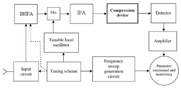
Fig. 2. Block diagram of a receiver with pulse compression.
Essentially, a receiver is a radio signal (RF) processing device that periodically scans a given frequency range by performing a frequency ramp (chirp) on the local oscillator. The result is time-separated pulses for each input signal (with different carrier frequencies) that can appear at the receiver input during the period of this chirp. The resulting periodic samples are subject to further processing.
The key block of the receiver is the compression device. It was for the purpose of its implementation that the RF signal, which was supplied to the input of the proposed receiver, was multiplied in the mixer by a chirp local oscillator signal with linear sweep. This provides a linearly variable intermediate frequency. The chirp signal is then fed to a dispersion delay line (DDL) with an equal but opposite chirp slope.
The compression device provides concentration of signal energy by compressing it in frequency and time, as well as separating samples by time at the output. The compression device is followed by a detector and an envelope detector that produces a video signal for each RF sample. Next, the parameters of the detected signals are assessed. Any necessary parameters can be measured, for example, arrival time, frequency, amplitude, phase difference for multichannel receivers, pulse duration, etc. In this way, monitoring can be carried out over a wide frequency band.
In the simplest configuration for performing frequency monitoring, after compression the signal is detected, amplified and fed into the vertical scanning system of the indicator (monitor). The frequency of the signals is determined by the position of the pulses on the frequency sweep.
3. Dispersive Delay Lines
DDLs on surface acoustic waves (SAW) are used to generate and compress signals with linear frequency modulation (chirp). The simplest classical DDL consists of two interdigitated transducers placed on a piezoelectric substrate. Interdigital transducers convert an electrical signal into a surface acoustic wave and vice versa. The transfer characteristic of the DDL depends on the shape of the converters.
Due to the so-called second-order effects (reflection of incident waves from the interdigitated converter, spurious signals due to additional reflections, edge effects), the analysis and development of DDL is a rather difficult task. Therefore, implementing dispersive SAW delay lines for signal compression applications can be complex and requires careful design and integration with the rest of the signal processing system.
The actual dispersion characteristics of SAW devices may impose limitations on the frequency range and bandwidth of chirp signals that are suitable for effective compression. This means that chirp signals with extreme frequency deviation (in this case, the local oscillator frequency range) or with rapid frequency changes may not be suitable for compression using such DDLs. The compression process using dispersive SAW delay lines can amplify noise components, affecting the signal-to-noise ratio. In addition, surfactant devices are sensitive to environmental conditions such as temperature and humidity, which can affect their performance and stability over time.
As an alternative version of the acoustic DDL, this paper considers a DDL model based on a high-frequency line of time delays with taps, each of which includes a bandpass filter. This model makes it possible to study the behavior of the compression device for various parameters of the processed signals. Dispersive delay with specified characteristics can be achieved using a set of bandpass filters. The general approach to constructing a DDL in this case is as follows.
A set of bandpass filters with different center frequencies is being developed. These filters can have different bandwidths to cover the signal frequency range of interest. Each bandpass filter introduces a different delay to the signals passing through it, depending on the center frequency of the filter. This frequency-dependent delay is the key to achieving the dispersion effect. Bandpass filters are connected in series, and the order of the filters determines the overall dispersion characteristic of the delay line.
Note that each filter will introduce a different phase shift and delay to the signals passing through them. These phase shifts and delays can cause different frequency components to shift in time, eg cause a mismatch that can lead to signal distortion. To ensure the correct time delay of the signals, it is necessary to align the outputs of all bandpass filters. Equalization ensures that the different frequency components of the input signal are properly delayed before they are combined. The equalization process consists of compensating for specified phase shifts and delays to ensure that the various frequency components are correctly synchronized in time when they are combined after passing through the bandpass filters. The frequency components are then synchronized, minimizing distortion and maintaining signal integrity. In other words, it is possible to recreate the original signal shape as accurately as possible after passing through bandpass filters.
It is important to note that accurate signal alignment requires precise knowledge of filter characteristics, including phase shifts and time delays, as well as a good understanding of the relationship between frequency, phase and time delay in signal processing. Mismatch can lead to errors and artifacts in the final reconstructed signal.
Once the outputs are equalized, they can be combined to produce a dispersion delay effect. The combined output will then have a frequency-dependent time delay, for example higher frequencies experience larger delays compared to lower frequencies.
It is important to note that constructing a dispersive delay line using bandpass filters requires careful design and calibration to accurately achieve the desired dispersion characteristics. In addition, factors such as filter quality, signal-to-noise ratio, and the choice of center frequencies and passbands for bandpass filters can influence the performance of the dispersion delay line.
Of course, the use of bandpass filters is only one of the possible alternative approaches to SAW-based DDL. There are other techniques and devices, such as fiber Bragg gratings and dispersion fiber, specifically designed to provide more precise and controlled dispersion for signal processing applications. The choice of the most suitable method depends on the specific requirements and applications. In this case, based on the objectives of this work, we limit ourselves to DDL using bandpass filters.
Thus, in the compression receiver under consideration, to convert pulses with a linearly varying frequency into signals with a shorter duration and larger amplitude, a compression circuit (dispersive filter) is used in the receiver, the model of which is a high-frequency line of sequentially connected time delays with taps, in each of which bandpass filter enabled.
4. The case of Receiving Signals with Different Frequencies
Consider a situation that is practically important for a passive radar, frequency monitoring, or reconnaissance receiver. To be specific, let's consider the simplest situation of detecting two signals.
If on the receiver, within its bandwidth B RF , two signals with different frequencies f , f are affected and durations respectively τ , τ , when these pulses impact the detector in a conventional panoramic receiver, a single video signal is formed. In this case, there is no way to separate the received signals by frequency.
In the proposed compression receiver with a frequency-modulated local oscillator (see Fig. 2), the input signals, after frequency conversion from the output of the amplifier, are fed to a dispersion filter, which is a compression device. In a dispersion filter, the delay time of a signal depends on its frequency. This dependence is chosen to be inverse to the law of changes in the frequency of signals generated at the output of the mixer. In this case, components of higher frequencies that arrived earlier are delayed for a longer time, and components of lower frequencies that arrived later are delayed for less time. Due to this, all frequency components are shifted in time in such a way that the pulses of the generated sequence running with the modulation period T , compressed to duration τ . As a result, the resulting output pulses correspond to signals with frequencies f and f do not overlap in time, and therefore are resolved in frequency. Thus, the frequency resolution increases.
Let's look at this mathematically. In the case of linear frequency modulation, during one modulation period T, the local oscillator signal is a modulated pulse, which can be expressed as follows:
s 1( t ) = sin[ ϕ ( t )] , (1)
where ϕ ( t )- instantaneous angle value (phase).
Instantaneous frequency value f (t) can be obtained by differentiation ϕ(t) with respect to time fi(t) =
1 ∂ ϕ ( t )
2 π ∂ t
To generate a linear frequency modulated signal f (t) should look like this fi(t)=(fe-fb)(t-tb)+fb, tb≤t≤te
where t pulse start time and t = t + T pulse end time; f and f the initial and final frequencies of the chirp signal, and their difference Δ f = f - f - frequency deviation.
So the phase ϕ ( t ) can be expressed as ϕ ( t ) = ∫ f ( t ) dt , which gives
ϕ ( t ) = 1 ( f e - f b )( t - tb )2 + fe ( t - tb ), tb ≤ t ≤ te
Let the input of the compression device, which is a matched filter, receive a chirp signal with a rectangular envelope, described by the equation:
s ( t ) = AE ( t )cos[ ϕ E ( t )] , (5)
where AE(t) is the envelope of the chirp signal a (t) = 1, by 0 ^ к- tb5 T
0, by 0 У |>-l„\У T where T is chirp signal duration.
Phase
ϕE(t)=ωb(t-tb)+πµ(t-tb)2+ϕЕ0,(7)
where ϕ is initial phase.
Parameter µ determines the slope of the dispersion characteristic of the device, ie scan speed by frequency
Δ f
µ= =const .(8)
T
The instantaneous angular frequency in a chirp signal varies linearly with time:
ΩE(t)=ωb +2πµ(t-tb)
and, using this connection between the instantaneous frequency in the chirp signal and its temporal position, we obtain
ϕЕ(f)=2πtb(f-fb)+π(f-fb)2+ϕЕ0
µ
Delay time t (ω) , according to definition, equals td(ω) = - ∂ϕ(ω) .(11)
∂ ω
Differentiating (10), we obtain td(ω)=tb+ 1(f-fb).(12)
µ
The number of periods in the chirp signal is equal to Tf and does not depend on the parameter µ .
Impulse response of a compression device h ( t ) , located in the receiver, is a time-reversed signal s ( t ) , in which the frequency change occurs in the opposite direction, that is h ( t ) ≈ s ( - t ) up to sometime delay and an arbitrary factor. Since the signal phase s ( t ) changes according to a quadratic law, then the phase h ( t ) must depend on time - ϕ ( - t ) . Then the impulse response of the matched filter should have the form
h ( t ) = АС 0( t )cos[ ϕ C ( t )] ,
where
ϕ С ( t ) = - ϕ E ( - t ) = ω 0( t - t 0) - πµ ( t - t 0)2 + ϕ C 0
and А ( t ) = A ( t ) . Matched filter output signal g ( t ) determined by the convolution integral [1] input signal with the impulse response of a compression device, which is essentially a matched filter. At t = 0 it is equal
∞
g ( t ) = ∫ s ( τ ) h ( t - τ ) d τ ≈ 0,5 T cos( ω t )sin c ( π Δ ft ),
-∞
where
sin c ( π Δ ft ) =
sin( π Δ ft ) π Δ ft
Thus, when a chirp signal (with a rectangular envelope) is applied to the input of the compression device, the envelope of the output signal has the form sin( x ) / ( x ) . The level of the nearest side lobes of this signal is approximately 13 dB below the level of the main maximum, as follows from the analysis of a function like (16).
Matched filter output g ( t ) , in the form of a narrow peak, is a compressed signal. Peak width t ≈ 1 Δ f , where Δ f - the width of the spectrum of the input signal, which is approximately equal to the frequency deviation in formula (7). In general, the width of the output peak is much less than the duration of the input FM signal Т , therefore, the matched filter is a pulse compression device.
The ratio of the durations of the input and output signals in a matched filter is the compression ratio, which is approximately equal to [1, 6]
Кcom = Т / t ≈ T Δ f . com com
In the case of estimating the delay time in radar, as is known [1, 6], this leads to an improvement in range resolution by a factor of К .
In this case, we are interested in frequency resolution, which determines the minimum difference between the frequencies f1 and f2 of two conditionally continuous signals at the receiver input, at which these signals form at the receiver output, i.e. at the output of the compression filter, distinguishable pulses. The position of these pulses on the time axis corresponds to the distinguishable frequencies. Therefore, the quantitative frequency resolution is determined by the width of the main lobe of the output signal of the compression device. From formulas (15) and (16) taking into account (8), since the term sin c(πΔft) =sinc(πµTt) equal to zero at t =π; -π, it follows that the width of the main lobe is inversely proportional T . In other words, from the technical side, the longer the delay time in the DDL, the narrower the main lobe and the better frequency resolution can be achieved in the compression receiver. Based on this, introducing the proportionality coefficient k , frequency resolution can be written as k δf = .
The value k depends on the design features and parameters of the receiver, in particular the DDL, and is assumed, as a rule, to be between 1 and 2.
The analysis carried out is simplified, since it does not take into account the return time during a linear change in frequency, the possible mismatch of the passbands of the receiver and the compression filter, and the advisable use of weighting filters to reduce the level of side foreheads; nevertheless, its results demonstrate the performance of the compression receiver in detecting and distinguishing input signals of different frequencies within the high frequency bandwidth.
5. Simulation of a Compressive Receiver with Passband Filters
Let's consider a model of a dispersive delay line based on a high-frequency delay line with taps, each of which includes a bandpass filter. The block diagram of such a model is shown in Fig. 3. Using a specialized package for modeling electronic circuits MultiSim (National Instruments), we will create, by analogy with the circuit shown in Fig. 2, and the approach described in Section 3, a model of 20 links, that is, consisting of 20 bandpass filters and, accordingly, delay lines and adders.
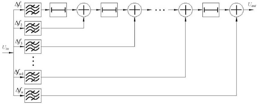
Fig. 3. Block diagram of a dispersive delay line model based on a high-frequency time delay line with taps with bandpass filters.
Let the chirp signal deviation Δ f = f - f be 0.4 GHz, with f = 1,5 GHz, f = 1,9 GHz, and the frequency tuning time Δ t be 200 ns. Then, for matched filtering, the bandwidth of one filter should be 0.02 GHz, and the duration of one time delay should be 10 ns, respectively. In addition, filtering of signals in bandpass filters should not occur simultaneously, but with a delay of +10 ns for each subsequent filter, starting with the lowest frequency.
To study the operating modes of the model, changes in input parameters were considered ( Δ f , f , f , Δ t )and the simulation results are summarized in tables 1-3.
As can be seen from table 1, with the input parameters and model parameters described above ( Δ f = 0.4 GHz, f = 1.5 GHz, f = 1.9 GHz, Δ t = 200 ns), the input chirp signal is completely convolved, which is the matched filtering mode.
In the case of a change Δ f , that is, a decrease/increase, for example, f by 0.1 GHz, as well as a change Δ t of 10 ns both upward and downward, the matched filtering mode disappears. The simulation results are shown in tables 2, 3.
At f = 3.0 GHz, f = 3.4 GHz, Δ t = 200 ns, the matched filtering mode is maintained with increasing filling density of the compressed pulse. The simulation result is shown in Table 4. Based on the simulation results, we can conclude that to preserve the matched filtering mode and, as a consequence, the full convolution mode, it is necessary and sufficient, given the model parameters, to preserve two parameters Δ f and Δ t .
Table 1. Matched filtering mode.
|
Initial local oscillator chirp frequency, fb , GHz |
Final local oscillator chirp frequency, , GHz e , |
Frequency tuning time from to , b e , Δ t , ns |
Compressed waveform |
|
1.5 |
1.9 |
200 |
U , В 10 5 0 ^^^ ^ -5 -10 190 195 200 Δ t , нс |
Table 2. Change in deviation Δ f of the input chirp signal.
|
Initial local oscillator chirp frequency, fb , GHz |
Final local oscillator chirp frequency, , GHz e , |
Frequency tuning time from to , b e , Δ t , ns |
Compressed waveform |
|
1.5 |
1.8 |
200 |
U , V 1 -0557-:3 -5 -10 190 195 200 Δ t , ns |
|
1.5 |
2.0 |
200 |
U , V10 5 0ITlTV^^ -5 -10 190 195 200 Δ t , ns |
Table 3. Change in tuning time of Δ t the input chirp signal.
|
Initial local oscillator chirp frequency, fb , GHz |
Final local oscillator chirp frequency, , GHz e |
Frequency tuning time from to , b e , Δ t , ns |
Compressed waveform |
|
1.5 |
1.9 |
190 |
U , V10 5---Г 0 AMIA^^^ -5 -10 190 195 200 Δ t , ns |
|
1.5 |
1.9 |
210 |
U , V10 5 Иь-------ngrt 0 i«S -51-------------------------OJ-i -10 190 195 200 Δ t , ns |
Table 4. Changes in the initial f and final f frequencies of the input chirp signal (matched filtering mode).
|
Initial local oscillator chirp frequency, fb , GHz |
Final local oscillator chirp frequency, fe , GHz |
Frequency tuning time from fb to fe , Δ t , ns |
Compressed waveform |
|
3.0 |
3.4 |
200 |
U , V10 5 0 HMHi™ -5 -10 190 195 200 Δ t , ns |
6. Discussion of the Results
As a result of computer modeling, the conditions for matching the parameters of the model under study and the received signal, that is, the matched filtering mode, were investigated and determined, and the conditions for maintaining consistency when changing the parameters of the received chirp signals were determined. According to the calculations given in Tables 1 - 4, it is clear that consistent filtering modes are achieved in Tables 1 and 4, since complete signal convolutions are obtained, and in Tables 2 and 3, filtering is inconsistent, since signal convolutions are absent or incomplete. Based on these results, we can conclude that to obtain a matched filtering mode, it is necessary and sufficient to maintain the equality of the chirp signal deviation Δ f and the frequency tuning time of Δ t the local oscillator chirp signal, and the same parameters of the dispersive delay line, respectively.
From the analysis and simulation results, it follows that the compression receiver, as a device that increases sensitivity and improves the ability to distinguish signals, is a useful tool, for example, in passive location [10, 11], frequency monitoring systems [12], electronic warfare [13] and other microwave applications [14].
In real applications, it is advisable to build multi-channel receivers of this type both to cover a wider frequency range [15, 16] and taking into account polarization diversity [17, 18], as well as systems with multiple inputs and outputs (MIMO) [19].
Our analysis and simulations have shown that the use of bandpass filters as a possible approach to constructing a dispersive delay line for receiver compression devices can be very useful in certain cases where the requirements and limitations associated with a particular application match the capabilities and characteristics of this method.
For example, the use of bandpass filters may be an appropriate choice if it is sufficient to introduce only a few specific frequency components with different delays. Obviously, bandpass filters provide the easiest way to achieve this. Thus, we have a simple and economical approach when working with a limited number of frequency ranges.
Bandpass filters are especially effective for narrowband signals, where the signal's bandwidth is small compared to the center frequency. In this case, the dispersion effect of bandpass filters can be more precise and controllable. Bandpass filters are especially readily available for the low to mid frequency ranges, and their characteristics can be clearly defined in these frequency ranges.
The development and implementation of DDL using bandpass filters is simpler and cheaper compared to other specialized devices or methods. This can be a practical choice when time and resources are limited.
In addition, there may be cases where the frequency resolution requirements for a particular application are not very high. Then the use of bandpass filters is most appropriate for introducing coarse frequency-dependent delays.
And finally, one of the important applications is the use of the completed development for educational purposes. Applying this approach to compression system design as a learning exercise using bandpass filters to construct a simple dispersive delay line is a useful way to understand the concept of DDL and signal processing compression systems.
At the same time, it is important to take into account the limitations of using bandpass filters as key elements of DDL. Among them, the following should be noted.
1. Bandpass filters have a fixed and specified frequency response, making it difficult to achieve highly accurate and flexible performance compared to specialized dispersive delay devices.
2. If the frequency bands of interest overlap significantly, it may be difficult to introduce separate delays for each band using bandpass filters without interference or crosstalk.
3. For applications requiring dispersion delay over a wide range of frequencies, the use of bandpass filters may become impractical due to filter size, complexity, and cost.
4. Bandpass filters can distort the signal, especially for wideband signals, affecting the overall accuracy of the output signal.
7. Conclusion
Thus, using bandpass filters as a dispersive delay line design approach may be appropriate for applications with simple frequency selection requirements, narrowband signals, and limited frequency resolution. However, for more demanding applications with precise dispersion control and a wider frequency range , specialized dispersion devices or techniques such as fiber Bragg gratings or dispersion fiber and, of course, modern digital processing techniques may be more suitable. The choice depends on the needs of specific applications and the trade-off between simplicity, performance and cost.
In this paper, a compression receiver device for passive location or monitoring has been proposed. In this receiver, arbitrary input signals are pre-processed using frequency conversion by multiplication with a local oscillator voltage whose frequency is periodically linearly varied. Such approach makes it possible to implement subsequent compression of the received pulses in a matched filter to increase the signal-to-noise ratio and improve frequency resolution. For this purpose, a model of a dispersive delay line has been developed based on series-connected high-frequency time delay lines with taps in the form of bandpass filters. The analysis of this model operating as part of a radio receiver with chirp signal compression has been performed.
A mathematical analysis of the processes of signal formation and processing has been performed for the case of receiving two continuous signals with different frequencies using the developed model. It has been shown that the frequency resolution of the proposed compressive receiver is inversely proportional to the total time delay in the compression device.
The proposed model can be implemented in devices for receiving unknown signals, in particular in passive radar, frequency monitoring devices, and reconnaissance receivers. It also makes it possible to study the processes of signal compression based on linear frequency modulation in different cases including traditional radar systems, in particular for educational purposes.
As the results of computer modeling, the conditions for matching the parameters of the model under study and the received signal have been investigated and determined, and the conditions for maintaining consistency when changing the parameters of the received chirp signals have been determined.
It has been determined that to preserve the matched filtering mode and, as a consequence, the full convolution mode, it is necessary and sufficient, given the model parameters, to preserve two parameters: chirp signal deviation Δ f and frequency tuning time Δ t . As a model of a dispersive delay line, a high-frequency delay line with taps, each of which includes a bandpass filter has been considered that makes it possible to study the behavior of the compression device for various parameters of radio signals to be processed.
As an example of practical use, the possibility of using dispersive delay lines to compress chirp signals is considered and a block diagram of a radio receiving device is presented, which includes a compression unit based on DDL to increase the sensitivity of the receiver and improve the resolution in both range and frequency.
Future research directions are associated with:
-
– Receiver operation modeling with the signals of different nodulation types;
-
– Detecting and processing noise-like signals by the compressive receiver;
-
– Analysis of the creating possibility of a system for identifying signals from the various radio emission sources.
Acknowledgment
We would like to express our gratitude to the reviewers for their precise and succinct recommendations that improved the presentation of the materials.
Conflict of Interest
The authors declare no conflict of interest.
References Radio Receiver with Internal Compression of Input Signals Using a Dispersive Delay Line with Bandpass Filters
- Merrill I. Skolnik, Radar Handbook, Third Edition, McGraw-Hill, 2008.
- F. J. Yanovsky, H. W. J. Russchenberg, and C. M. H. Unal, "Retrieval of information about turbulence in rain by using Doppler-polarimetric Radar," in IEEE Transactions on Microwave Theory and Techniques, vol. 53, no. 2, pp. 444-450, Feb. 2005, doi: 10.1109/TMTT.2004.840772.
- Yakov D. Shirman, “Method for Improving the Resolution of the Radar and the Device for its Implementation,” Patent No. 146803 on Application No. 461 974/40, Priority date: July 25, 1956, Publication date: January 1, 1962 (in Russian).
- Charles E. Cook, “Pulse Stretching and Compression Radar System,” US Patent No. 3400396A, Priority date: November 14, 1955, Publication date: September 3, 1968.
- F. J. Yanovsky, "Glimpses of early radar developments in Ukraine and the former Soviet Union," in URSI Radio Science Bulletin, vol. 2016, no. 358, pp. 35-68, Sept. 2016, doi: 10.23919/URSIRSB.2016.7909881.
- D.E. Vakman, Sophisticated Signals and the Uncertainty Principle in Radar, Springer, Berlin, Heidelberg, 1968.
- C. E. Cook and M. Bernfeld, Radar Signals: An Introduction to Theory and Application, Artech House, 1993.
- K.F.A. Hussein, A.O. Helmy, and A.S. Mohra, “Radar Pulse Compression with Optimized Weighting Window for SAR Receivers,” Wireless Pers Commun 126, 2022, pp. 871–893. doi.org/10.1007/s11277-022-09774-z.
- D. Klaus, Breuer, J. S. Levy, and H. C. Paczkowski, “The compressive receiver: a versatile tool for EW systems,” Microwave Journal (ISSN 0192-6225), Vol. 32, Issue 10, Oct. 1989, pp. 81-98.
- M. Malanowski and K. Kulpa, "Two Methods for Target Localization in Multistatic Passive Radar," in IEEE Transactions on Aerospace and Electronic Systems, vol. 48, no. 1, pp. 572-580, Jan. 2012, doi: 10.1109/TAES.2012.6129656.
- F. Yanovsky, “Methods and means of remote definition of clouds' electrical structure,” Physics and Chemistry of the Earth, 1997, 22(3-4), pp. 241–245. Published by Elsevier Science Ltd.
- O. Shcherbyna, M. Zaliskyi, O. Kozhokhina, and F. Yanovsky, “Prospect for using low-element adaptive antenna systems for radio monitoring stations,” International Journal of Computer Network and Information Security, 2021, 13(5), pp. 1–17. DOI:10.5815/ijcnis.2021.05.01
- Sergei Vakin, Lev Shustov, and Robert Dunwell, Fundamentals of Electronic Warfare, Artech House, 2001.
- A.I. Nosich, Y.M. Poplavko, D.M. Vavriv, and F.J. Yanovsky, "Microwaves in Ukraine," in IEEE Microwave Magazine, vol. 3, no. 4, pp. 82-90, Dec. 2002, doi: 10.1109/MMW.2002.1145680.
- F. J. Yanovsky and R. B. Sinitsyn, "Ultrawideband Signal Processing Algorithms for Radars and Sodars," 2006 3rd International Conference on Ultrawideband and Ultrashort Impulse Signals, Sevastopol, Ukraine, 2006, pp. 66-71, doi: 10.1109/UWBUS.2006.307160.
- R. B. Sinitsyn and F.J. Yanovsky, “Copula ambiguity function for wideband random radar signals,” 2011 IEEE International Conference on Microwaves, Communications, Antennas, (COMCAS 2011), Tel Aviv, Israel, 2011, pp. 1-4, doi: 10.1109/COMCAS.2011.6105843.
- F. J. Yanovsky, H. W. J. Russchenberg, L. P. Ligthart, and V. S. Fomichev, “Microwave Doppler-polarimetric technique for studying of turbulence in precipitation,” IGARSS 2000. IEEE 2000 International Geoscience and Remote Sensing Symposium, Honolulu, HI, USA, 2000, pp. 2296-2298 vol.5, doi: 10.1109/IGARSS.2000.858387.
- F.I. Yanovskij (Felix Yanovsky) and V.A. Panits, “The Use of Antenna with Controlled Polarization to Detect Areas of Hail and Icing,” Radio electronics and communications systems, 1996, Vol. 39, pp. 20-25 (translation of “Application of an antenna with controlled polarization for the detection of hail and icing zones,” Izvestiya VUZ: Radioelektronika, 1996, 39(10), pp. 32–42, in Russian).
- R.B. Sinitsyn, F.J. Yanovsky, “MIMO radar copula ambiguity function,” European Microwave Week 2012: “Space for Microwaves”, EuMW 2012, Conference Proceedings, 9th European Radar Conference, EuRAD 2012, Amsterdam, Netherlands, 2012, pp. 146–149.
