Real-time Corresponding and Safety System to Monitor Home Appliances based on the Internet of Things Technology

Author: Nalinsak Gnotthivongsa, Huangdongjun, Khamla Non Alinsavath
Journal: International Journal of Modern Education and Computer Science @ijmecs
Article in issue: 2 vol.12, 2020.
Free access
Smart Home is a versatile system that incorporates several elements, i.e., visual intercom, home security, remote monitoring of home appliances, remote video surveillance, care systems and online education systems. The basic goal of a smart home is to connect various information-related communication devices, household appliances and home security devices in the home, to an intelligent system for centralized or remote monitoring, control and family affairs management. IoT refers to the infrastructure of connected physical devices, which is growing at a rapid rate, as a huge number of devices and objects are getting connected to the Internet. Internet of Things (IoT) is a significant part of the smart home scenario. It performs information exchange and communication between the home environment and smart system, through multiple sensors, such as photoelectric sensors, radio frequency identification, and so on. Its purpose is to realize real-time connection between objects and objects, objects and people, all items and networks, and to facilitate identification, management and control. This proposed paper presents a smart home application to support real-time correspondence to reduce the cost of implementation, to pursue life intelligence and comfort, with the hope that the system is able to provide a much more convenient and efficient energy saving consumption for the daily activities of the family. Having this application helps a lot of user to know the real-time notification in case of emergency occurs within the house, the advanced feathers of this application consisting of monitoring, control system and information support system as one stop-service application in order to assist user to know more environment context and being intermediate between user and home appliances. For example, if someone forgets to turn off the light when they are out of the home, and all other home appliances are active without being used. As such, a smart home, or home automation, which induces technology for the home atmosphere provides ease of use and the necessary protection to its occupants.
Internet of Things, Smart home, Control system, Sensors
Short address: https://sciup.org/15017579
IDR: 15017579 | DOI: 10.5815/ijmecs.2020.02.01
Text of the scientific article Real-time Corresponding and Safety System to Monitor Home Appliances based on the Internet of Things Technology
IoT or the Internet of Things refers to the network of connected physical objects which can communicate and exchange data without the need of any human intervention. It has been formally defined as the “Infrastructure of Information Society”, because IoT allows users to collect information from all kinds of mediums, such as humans, animals, vehicles, and kitchen appliances. Thus, any object in the physical world, which can be provided with an IP address to enable data transmission over a network, can be made part of the IoT system by embedding it with electronic hardware, such as sensors, software and networking gear. IoT is different than the Internet, as it transcends Internet connectivity by enabling everyday objects which use embedded circuits to interact and communicate with each other, thus utilizing the current Internet infrastructure.
The Internet of Things [1] refers to ubiquitous end devices and facilities, including sensors with intrinsic intelligence, mobile terminals, industrial systems, building control systems, home intelligence devices, video surveillance systems, externally enabled, such as RFID-attached assets, individuals and vehicles carrying wireless terminals. In addition, there are smart parts or animals, smart dust using a variety of wireless and/or long distance and/or short-range communication networks to achieve interoperability, application based integration (Grand Integration / MAI), and cloud-based SaaS operations, as well as other modes. These include intranet (Intranet), private network (Extranet), and/or the Internet (Internet) environment, using appropriate information security mechanisms [2] to provide secure, controllable, and even personalized real-time online monitoring, location and traceability, alarm linkage, dispatching command, plan management, remote control, security, remote maintenance, online upgrades, management and service functions, safety, environmental protection, and camp integration TaaS services.
Smart Home [3,4] is a versatile system which incorporates the visual intercom, home security, remote monitoring of home appliances, remote video surveillance, telemedicine diagnostics and care systems, online education systems, and home movie star systems [5]. With the development of smart homes, it will bring about a much richer content, more complex systems, and much more functions [6].
This paper introduces a smart home system with regards to the Internet of Things approach, to examine the real environment using different kinds of sensors, which consist of embedded technology, application and human behavior monitoring across different real-time examples with the purpose of providing real-time information through smart application and to reduce the damage that will be happened to the assets and human lives when an unexpected disaster happens during the people are out of their home and to know issue’s notification in advance. Advanced technology such as movement sensors, smoke detection sensors and application development based on the smart home application are considered to be applicable to the smart system, to ensure that the system can respond to the user in time when there are issues around the home environment, which are able to be controlled and managed directly from the proposed system such as the door can be atomically opened when there is an issue inside the house and alarm to the user to protect their properties in time.
The organization of this paper is as follows; Section 2 presents a literature review, Section 3 presents the overall principles and design of the system, Section 4 covers the system implementation and configuration, Section 5 elucidates the experiments and discussion of the results, and finally, Section 6 offers a brief conclusion to the proposed work.
-
II. Literature Review
The design and implementation of the security for Smart Homes based on the GSM technology was discussed by Govinda et al. (2014) and provided two methods to implement the home security using IoT [1]. One used motion detection web camera, in order to sound an alarm or send messages to the owner. This method of detecting intrusion was quite good, albeit, somewhat
expensive, due to the cost of the cameras involved in the process. The cameras needed to be of good quality, which meant that it should have a wide range, and the picture quality should be of high enough quality to detect movement. Also, if the user went for movable cameras, such as dome cameras, it would cost even more than the fixed ones. SMS based systems using the proposed GSM by Karri and Daniel (2005) used internet services to send messages or alert to the house owner, instead of the conventional SMS. [2] Jayashri and Arvind (2013) implemented a fingerprint-based authentication system to unlock doors [3]. This system helped users by only allowing the users whose fingerprints were authorized by the owner of the house to enter. This system can also be used to monitor who all have used the sensor to gain entry into the house. The system is coupled with a few more home protection features, such as gas leakage and fire accident detection. Although a good system, the fingerprint sensors are expensive and complex (as they need increased sensor resolution) to integrate into an IoT setup. Some experts also argue that only relying on a fingerprint sensor is not wise, as it is relatively easy to lift someone’s fingerprints and replicate them, which is why it is always advised to use fingerprint scanners in a two factor authentication system, where an additional layer of security is available in the form of a PIN, passcode, or voice recognition, etc. Some researchers proposed the idea of a robust IoT home security system, where the fault in of one component in the system did not lead to the failure of the whole system [4]. The idea of using multiple devices, which may or may not be directly compatible with each other, can be made to work in such a way that they can replace an existing component of the system in case of a fault. In tandem to this, the model has the ability to use an overlap between various devices, which would result in preserving energy, thus making the model more efficient. An example provided of the said model uses a temperature sensor, Wi-Fi module and a door sensor to replace a faulty camera. The authors successfully demonstrated this. Such systems are useful for people with energy efficiency in mind, and for those who need a high degree of robustness with their security systems or are willing to spend more money than usual. Laser rays and LDR sensors are used to detect intrusion using the proposed movement in 2016 [5]. The way the system works, is that a laser is focused towards a LDR sensor, and the moment that the contact of the laser to the LDR sensor is broken, the alarm connected to the sensor goes off, alerting the neighbors, and sends a SMS to the owner.
This system solves the problem of covering places which are out of range from the fixed cameras but faces the same difficulties as systems which consist of GSM modules to send text messages. The delivery of messages is dependent on the network coverage. Also, due to the nature of lasers being a straight-line beam, it can be avoided by intruders who know the system, and are capable of dodging the lasers, rendering the whole system useless.
-
III. Overall And Principles Of System Design
This project aims to design a smart home system. According to the design requirements of the system, the control system uses a distributed control for all parts of the smart home [7], including remote monitoring of home appliances (including desk lamps, fans) with voice command. Upon prompting the password lock anti-theft function, the window automatically closes to prevent the child from falling to the building part, and the smoke concentration monitoring automatic alarm part [8]. Each module is independent of one another, and failure of one module does not affect the operation of other modules.
The smart home system uses the S3C2440 processor, and the controller controls the remote monitoring of the home appliance module to detect the temperature, the smoke module, the password lock module, and the lighting. In the actual development, the driver of each module was written using the ARM Linux. After compiling and loading the driver, the application layer could then be used to operate the hardware module. The mobile phone communicated with the hardware module through the application layer program, to achieve the purpose of controlling the hardware. Other hardware and modules that were used to implement this work included the Mini2440 ARM, Samsung S3C2440A processor, and the TC35 Module, a dual-band 900/1800 MHz, which is highly integrated with the GSM module from Siemens.
This system uses the tc35 to remotely monitor home appliances in order to transfer information over voice and data, power saving, communication interfaces, temperature detections using the ds18b20 temperature sensor to measure the temperature around the home, and the small space environment of the electronic device’s position.
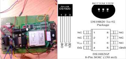
Fig.1. TC35 Module Circuit and DS18B20 Package schematic
TC35 is a complete wireless IOT module introduced by Siemens. It consists of IOT baseband processor, IOT RF module, power supply module (ASIC), flash memory, ZIF connector, antenna interface and SIM card holder. It can realize data transmission and Short Message Service in the system scheme quickly, safely and reliably.
The system uses software to control the TC35 module communication module very flexibly, and the detection of excessive hardware signals is also well avoided. When the other pins of the TC35 are not in use, if the pin is an output, the pin is usually left floating; if the pin is an input pin, the pin needs to be pulled up through a 10Ω resistor. In addition, the IGT pin needs to be pulled up because the IGT pin is the pin that controls the operation of the TC35 module. And cortexA8 is connected to this pin, so we can use cortexA8 to control the working mode of TC35 module. Since the TC35 module is fully functional, the power pins of the TC35 module are connected together, so there is no need for any RF processing and signal processing. In addition, the IGT pin is the TC35 mode fast start pin and is connected to the ALE pin of the cortexA8. In order to make the TC35i enter the working state after the system is powered on, a low pulse of more than 100ms must be added to the ALE pin. The duration of the level drop cannot exceed 1ms. The following is the interface design of the TC35 module.
The system was mainly proposed for remote control of the user's home. The main functions were remote monitoring of the home appliance operation, temperature and smoke sensors to detect the home’s temperature and air quality, and monitoring of the family’s property through use of photoelectric sensors. The interface between the ds18b20 and the arm processor was very simple. Users only needed to connect the signal line of the ds18b20 to a bidirectional port of the control line. This system connected the signal line of the ds18b20 with the gpe0 pin of the s3c2440.
-
A. The hardware resources of the system development.
-
- Samsung S3C2440A processor: The main
frequency is 400MHz, the highest is 533MHz.
-
- SDRam Memory: 64M SDRAM. 32 bit data bus Flash Storage: 256M Nabd Flash, power down nonvolatile.
-
- Real Time Clock: Internal real time clock (with backup lithium battery).
-
- Tc35 module: Single power supply 3.3v ~ 5.5v, Dual-band GSM900MHz and DCS1800 MHz (Phase 2+).
-
- Temperature sensor: voltage: 3~5v/dc, temperature range is -55 ° C ~ +125 ° C, the inherent
temperature resolution is 0.5 ° C.
-
- mq-2 smoke sensor: Alarm concentration:
0.65~15.5% ft, power: 12vdc/9vdc
-
- Photoelectric sensor
-
- isd1760 voice chip
-
- Relay
-
- Operating system support: Linux2.6.32.2 + Qtopia-2.2.0+QtE-4.6.1 (the original dual graphics system coexists, seamless switching).
-
B. Embedded Software Development Level
An embedded Linux system can be divided into three levels, from a software perspective:
-
1. The boot loader, including the boot program (optional) that is hardened in the firmware, and the bootloader part.
-
2. Linux kernel, a custom kernel specific to the embedded platform.
-
3. File system, including system commands and applications. A typical space allocation structure diagram of a solid-state storage device, with the
BootLoader, kernel boot parameters, kernel image and the root file system image as shown in Figure 2.
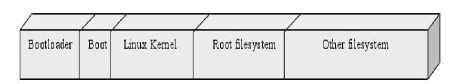
Fig. 2. Space allocation structure.
The bootloader is a program, and its role is to load the operating system. The BootLoader (boot loader) is the first piece of software code after the system is powered up. Through this code, hardware initialization can take place, build a memory space map, prepare the hardware environment for the operating system kernel, and boot the kernel. The bootloader is the lowest level and is first run to boot the operating system. It is easy to see that the bootloader is the underlying program, so its implementation is heavily dependent on the hardware, especially in the embedded world. Therefore, it is almost impossible to build a common BootLoader in the embedded world. Despite this, some powerful BootLoaders that support more hardware environments are supported by a wide range of users and enthusiasts, resulting in some widely recognized across more general bootloader implementations.
A file system is a mechanism for organizing data and metadata on a storage device. This mechanism facilitates the interaction between the user and the operating system. If there is no file system in Linux, therefore, the interaction between the user and the operating system is broken, and all application user programs have no way to run.
-
IV. System Implementation And Configuration
Linux systems divide devices into three types: character devices, block devices, and network interface devices.
The devices used in the design of this system are all character device drivers. Here, we mainly explain character devices and related content. A character device is a device which can read and write data only one byte at a time. It cannot read data in the device memory randomly. The main work in the driver is to initialize, add and delete the cdev structure, apply and release the device number, and fill in the operational function in the file_operations structure, as well as implement the important functions, such as read(), write(), and ioct1() in the file_operations structure.
The relationship between the cdev structure, file_operations, and user space call drivers is shown To make ensure the device works well, one must first load the device driver module as shown in Figure 4.2, and then correctly call the open(), read(), write(), ioctl() function operating system’s hardware devices.
In addition, the upper application is compiled in qtopia, and each module of the smart home system must not interfere with each other. The failure of one module should not affect the operation of other modules. To ensure each module can work alone, thread technology, and timers for each module is inserted into the module's timer function. The following describes the debugging process of several modules of this design.
-
A. Implementation of gsm remote control module (Mini2440 Serial Port)
The actual programming process mainly consists of two components. One is the hardware driver of the serial port, and the other is the application on the file system.S3c2440 itself, which comes with 3 serial ports uart0, 1, 2, of which the uart0 has rs232 level conversion, uart1, uart2 and the output point level is the ttl level. But the uart0 is needed to start the system from the NFS, which was used in the Uart2 development and connected to the gsm module via the 232 circuit. The kernel source code of the development board came with a serial port driver. There was no need to write the drivers during the program development.
In Linux, everything can be seen as a file. When a user wants to use the serial port at the application layer, they first need to open the serial port:
int fd;
fd=open(“/dev/ttySAC1”,O_RDWR);
If (-1==fd)
{
/ * cannot open the serial port 2 * /
Perror ("prompt error!");
}
It is necessary to set the serial port up correctly, including setting the baud rate, the effect bit, and the stop bit. Setting the serial port helps to set the member values of the struct termios structure.
Struct termios
{
Unsigned short c_iflag;//Input mode flag Unsigned short c_oflag;//output mode flag Unsigned short c_cflag;//control mode flag Unsigned short c_lflag;//local mode flag Unsigned char c_line;//control protocol Unsigned char c_cc[NCC];//Control mode characters
};
-
B. Implementation of the temperature acquisition module
The ds18b20 temperature sensor provides 9- to 12-bit (binary) temperature readings, indicating the temperature information of the device has been sent to, or from the ds18b20 via the single-wire interface. Only one line (common) is required from the host cpu to the ds18b20, and two types of ds18b20 are available. The power supply mode, one of which is the data bus power supply mode, can save one wire, but the measurement temperature is much longer. The second is the external power supply mode, whereby the ds18b2o’s working power is connected via the vdd pin, of which the i/o line does not need a strong pull-up. If there is is a problem of insufficient power supply current, this will help guarantee the conversion accuracy. Therefore, although one wire is used, the measurement speed is faster, and the BUS can be connected to multiple ds18b20 sensors to form a multi-point temperature measurement system. In order to achieve timely multi-point acquisition temperatures, this design used an external power supply.
The DS18B20 measured from -55 degrees Celsius to +125 degrees Celsius in increments of 0.5 degrees Celsius, and converted temperatures to the digital form in 1 s (typical). Each DS18B20 was factory-supplied with a unique serial number in multiples of the DS18B20, which can be stored on the same single-wire BUS for multichannel temperature acquisition. The serial number value of the DS18B20 was stored in the ROM (Read Only Memory) inside the DSl8B20. For multi-channel measurement, the DS18B20 ROM search command was used to search all the sensors on the single-line BUS, and then the DS18B20 was initialized to skip the ROM command. The RAM temperature conversion command after the DS18B20 the single line temperature conversion was completed was located on the DS18B20, and read its digital temperature value with the matching ROM command and the RAM temperature read command.
The digital temperature sensor ds18b20 directly converts the analog temperature signal into a digital signal and then outputs it via serial communication. Therefore, the key to temperature acquisition was the communication protocol of the ds18b20. In order to ensure the integrity of the data conversion and transmission, ds18b20 devices must use strict communication protocols to communicate with the s3c2440 processor. Data communication protocol include sensor initialization, data execution ROM operation, command and memory operation. The initialization protocol defined the reset and the presence of the pulse timing. The data execution protocol defined if the processor read 0 and 1 timings and wrote 0 or 1 in the timing. All commands and data were sent in bytes, the low bit being first, the high bit coming after, across the ds18b20 data communication timing.
When the processor pulled the single-wire BUS DQ from the logic high to the logic low, it initiated a write sequence. All write timings had to be completed within 60μs~12μs, and at least 1μs recovery time was required between two consecutive written timings. During the entire timing of writing "0", the bus remained at a logic low level, and during the writing of the "1" timing, the processor first pulled the single-wire BUS to a logic low level, and released the BUS within 15 μs after the start of the timing, writing "0" and "1".
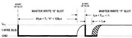
Fig. 3. Write "0" and write "1" timing diagram.
The main functions written by the driver layer during data acquisition are as follows:
-
1) static int ds18b20_init(void);//data initialization
-
2) static unsigned char write_byte (void); / / read data to DS18B20
-
3) static unsigned char read_byte (void); / / write data to DS18B20
-
4) static ssize_t ds18b20_read
On the other hand, the implementation of the smoke sensor module was conducted and processed in the system, and the mq-2 gas sensor could detect a variety of flammable gases. When there was a flammable gas in the environment, the conductivity of the sensor increased with the concentration of flammable gas in the air. The change in conductivity can be converted to an output voltage signal corresponding to the gas concentration using a simple circuit. The concentration of the flammable gas in the environment is determined according to the magnitude of the voltage output by the sensor.
The MQ-2 gas sensor outputs a voltage signal, and the processor converts the corresponding voltage value into a corresponding value. The s3c2440 has its own A/D conversion function, and the A/D conversion chip corresponds to the device file in the embedded system, "/dev/adc". Firstly, the system calls the function int fd_adctest = open ("/dev/adc", O_RDWR) to open the A/D conversion device in the embedded device. If the device fails to return -1, the system function can be used later, using the fd_adctest to operate the device. To turn off the smoke sensor, the close(fd_adctest) function is used. The figure below displays the connection diagram of the smoke sensor.
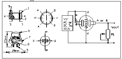
Fig. 4. Smoke sensor wiring diagram.
As shown in the figure above, the other MQ-2 sensors have 6 pin-shaped tube pins, 4 for signal output, and 2 for heating current. Assume the sensor surface resistance is Rs, which is obtained via outputs of the effective voltage signal on the load resistor RL connected in series with it. The relationship between the two can be obtained by referring to the MQ-2datasheet as shown in the Equation 1 below:
R s/ ( V VC - V RL V (1)
/ RL ArL
According to the working principle of Equation 4.1 and mq-2 (the conductivity increases with the increase of the gas concentration, the reciprocal of the resistive conductivity; and so the resistance is reduced, which makes its characteristic equivalent to a sliding rheostat).
V out
R L V c
R + R, sL
V c For the loop voltage, that is, the power supply voltage, is added between the 1st and 3rd feet of the mq-2
VR sensor. out Is the sensor 4 pin, 6 pin output voltage, s Is the body resistance of the sensor. If the gas concentration rises, it will lead to s decline, and s then drops of, and the mq-2 will increase the voltage output from the 4th and 6th feet of the mq-2, so that the gas concentration will increase and the output voltage will increase.
The a/d converter of the s3c2440 development board converts the input analog voltage signal into a number between 0-1023. The larger the number converted, the larger the voltage, and the greater the smoke concentration. Suppose the number after the a/d conversion in the program is C , one can set two values in the program C 、C Hypothesis C =400,C =800, if C > C The system opens the indoor exhaust fan and discharges harmful gases outside. IfC > C the system’s alarm buzzer goes off.
-
V. System Testing And Result Of The Experiment
The development platform of the smart home system was based on the mini2440 development board launched by the friendly arm. Its core controller was the S3C2440. Qtopia is used as the application layer program design, including the system interface design in the project development. Qtopia is a comprehensive application platform developed by Trolltech (now acquired by Nokia) for consumer electronics devices with embedded Linux operating systems. Qtopia includes a complete application layer, flexible user interface, window operating system, application launcher and Development Framework. Figure 4 (left) is the overall rendering of the smart home system.
In order to better display the work and capture the functions of each module of the work, the authors have separated the entire system. In the development, the smart home system was designed as an application loaded under the mini2440 column. After opening the program, the smart home system controller interface is shown in Figure 3 (Right). The system interface displays the indoor temperature condition and the indoor air quality status. Under normal circumstances, the “The air quality is well” is displayed, and the working status of the appliance is displayed at the same time.
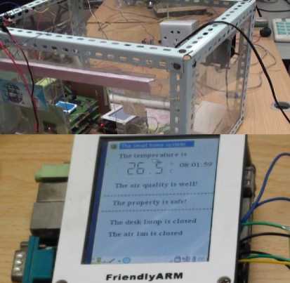
Fig. 5. Overall effect of smart home (top) and smart home system program interface (bottom).
In terms of security for the home and surrounding environment, the smoke alarm module was implemented and tested under actual conditions, to detect smoke around the home when a fire or emergency occured. The smoke alarm module displayed “The air quality is well” when the indoor air quality was good, and when the smoke fog was high, the controller displayed “The air quality is not well!”, and the system turned on the exhaust fans to keep out harmful gasses. When the smoke concentration was too high, the controller displayed “The air quality is bad!” and started the buzzer’s alarm went off.
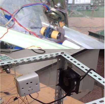
Fig. 6. Detects an abnormality a voice alarm (top) and system will alarm when the door is opened ().
The smoke alarm module displayed “The air quality is well” when the indoor air quality was good. When the smoke fog is high, the controller displays “The air quality is not well!”, and the system turns the exhaust fan to open the indoor harmful gas. Exhaust outdoors; when the smoke concentration is too high, the controller displays
“The air quality is bad!” and starts the buzzer to perform a smoke alarm
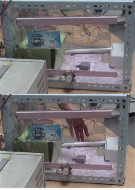
Fig. 7. The system is silent while there is no human around the system and the window remains closed (top) and the system will make a voice alarm and the window is opened when user is moving at the sensor range (bottom).
During the test, the smoke was created using a lighter, and the smoke sensor was tested for detecting the harmful gas from the lighter. After testing, the functional module worked normally. Figure 4 below shows the smoke sensor test lighter gas, and Figure 4 shows that when the aversive concentration was high, the system and the exhaust fan pushed out the harmful gasses.
Furthermore, in order to prevent accidents at home, human detection was added to the system to monitor the real situation and real objects using the human body infrared sensor, which was set up at the doors and windows to detect the presence of humans around the network range. The system was highly accurate in terms of detection as to whether there was anyone near the windows and doors. Figure 5 (left) shows that no human body was detected near the window, and that no alarm went off in the coverage area. Figure 6 (right) shows that the system detected a human body via the infrared sensor at the window, and the alarm had been alerted through the system to the user via real time response.
Table 1. Sensor Data From Real Environment Monitoring Around Home
|
No |
ID |
Temperat ure |
Human Detection |
Voice Alarm |
Window detects |
Date/ Time |
|
1 |
101 |
26.5 |
0 |
Off |
Closed |
03/08/1 9 13:09 |
|
2 |
102 |
26.5 |
1 |
On |
Open |
03/08/1 9 13:10 |
|
3 |
103 |
27.0 |
1 |
On |
Open |
03/08/1 9 13:11 |
|
4 |
104 |
27.0 |
1 |
On |
Open |
03/08/1 9 13:12 |
|
5 |
105 |
27.0 |
0 |
Off |
Closed |
03/08/1 9 13:13 |
According to the above table 1, After the function is completed and can monitor the system from the proposed function, all the real data from the sensors are stored in the Database. We can use the database to collect the data for one month and will automatically save once per minute. The reason we collect for one month is because we would like to monitor the activity and power usage for long term monitoring. The database enables us to store the data for one month after that the system will regularly replace rows with new data from real conditions every month. The shown data come from environment detection as real-time information when user operated the system in order to be able to support information to the user and make sure that the system work perfectly and appropriately.
-
VI. Conclusion
The authors have learnt a lot of relevant knowledge in the process of researching this topic and realize the important aspects of a smart home system. The authors also found many deficiencies, such as the lack of friendly system interfaces and the need for improvement of the overall wiring of the model. The function of the smart home system needs to be continuously improved. In addition, the stability and anti-interference of the system still needs to be improved. Therefore, authors have proposed this smart application in order to classify and support full the needed information to maximize the demand in term of utilization and usability of the proposed system. The proposed works have touched many fields and devices such as smart home system, control system, sensors and other related devices to have completely smart system. On the other hand, this research mainly consisted of the following work: In-depth study of the status quo and development trends of smart home systems at home and abroad, based on the design of the embedded remote home monitoring system framework. Established an embedded system platform and development environment, including the reduction and porting of the embedded Linux, as well as the production and loading of embedded Linux file system. Designed and implemented the smart home system model. The smart home system implemented the GSM remote control module, the temperature and smoke data acquisition module, and the password lock anti-theft function module using voice command prompts to prevent children falling from the building module. Each module worked with one another and did not affect one another. After testing, each module could operate normally. Furthermore, in the future work, the system will be integrated with other sensors like PDR sensors, LDR Sensors and protype platforms such as Node MCU in order to improve the system and have more function to smoothly operate and maximize the need of users.
References Real-time Corresponding and Safety System to Monitor Home Appliances based on the Internet of Things Technology
- Chan M, Campo E, Estève D, et al. Smart homes - current features and future perspectives.[J]. Maturitas, 2009, 64(2):90-97.
- Cook D J , Youngblood G M , Iii E O H , et al. MavHome: An agent-based smart home[C]// IEEE International Conference on Pervasive Computing & Communications. IEEE, 2003.
- Han D M, Lim J H. Smart home energy management system using IEEE 802.15.4 and zigbee[J]. IEEE Transactions on Consumer Electronics, 2010, 56(3):1403-1410.
- Han D M, Lim J H. Design and implementation of smart home energy management systems based on zigbee[J]. IEEE Transactions on Consumer Electronics, 2010, 56(3):1417-1425.
- Das S K, Cook D J, Battacharya A, et al. The role of prediction algorithms in the MavHome smart home architecture [J]. IEEE Wireless Communications, 2002, 9(6):77-84.
- Chen L, Nugent C D, Wang H. A Knowledge-Driven Approach to Activity Recognition in Smart Homes [J]. IEEE Transactions on Knowledge and Data Engineering, 2012, 24(6):961-974.
- Chen L, Nugent C D, Wang H. A Knowledge-Driven Approach to Activity Recognition in Smart Homes.[M]. IEEE Educational Activities Department, 2012.
- Demiris G, Rantz M J, Aud M A, et al. Older adults'' attitudes towards and perceptions of ‘smart home’ technologies: a pilot study [J]. Medical Informatics, 2004, 29(2):8.
- Pedrasa M A, Spooner T D, Macgill I F. Coordinated Scheduling of Residential Distributed Energy Resources to Optimize Smart Home Energy Services [J]. IEEE Transactions on Smart Grid, 2010, 1(2):134-143.
- Govinda K and Sai Krishna Prasad K and Sai ram susheel 2014 Intrusion detection system for smart home using laser rays International Journal for Scientific Research & Development (IJSRD) 2 176-78
- Karri V and Daniel Lim J S 2005 Method and Device to Communicate via SMS after a Security Intrusion 1st International Conf. on Sensing Technology Palmerston North New Zealand 21-23
- Jayashri B and Arvind S 2013 Design and Implementation of Security for Smart Home based on GSM technology International Journal of Smart Home 7 201-08
- Sowjanya G and Nagaraju S 2016 Design and Implementation Of Door Access Control And Security System Based On Iot Inventive Computation Technologies (ICICT), International Conference on Inventive
- Cristian C, Ursache A, Popa D O and Florin Pop 2016 Energy efficiency and robustness for IoT: building a smart home security system Faculty of Automatic Control and Computers University Politehnica of Bucharest, Bucharest, Romania 43
- Lee C T, Shen T C, Lee W D and Weng K W 2016 A novel electronic lock using optical Morse code based on the Internet of Things Proceedings of the IEEE International Conference on Advanced Materials for Science and Engineering eds. Meen, Prior & Lam
- Pooja P, Mitesh P, Vishwa P and Vinit N 2016 Home Automation Using Internet of Things Imperial Journal of Interdisciplinary Research (IJIR) 2 648-51
- Anitha A, Paul G and Kumari S 2016 A Cyber defence using Artificial Intelligence International Journal of Pharmacy and Technology 8 25352-57 [9] Anitha A, Kalra S and Shrivastav 2016 A Cyber defence using artificial home automation system using IoT International Journal of Pharmacy and Technology 8 25358-6
