Real Time Depth Data Refurbishment in Frequency Domain and 3D Modeling Map Using Microsoft Kinect Sensor

Author: Kapil S. Raviya, Dwivedi Ved Vyas, Ashish M. Kothari
Journal: International Journal of Image, Graphics and Signal Processing(IJIGSP) @ijigsp
Article in issue: 11 vol.8, 2016.
Free access
The present decade has seen the growth of both, the software and hardware for three dimensional televisions in real time applications. Depth map is fundamental key of 3-Dimensional algorithms. Reliable depth map is an acceptance in 3D transmission, analysis and compression of algorithm. Computer vision and pattern recognition research fields use sensor like low cost Microsoft kinect. Kinect sensor suffers from some problems of noise, poor accuracy and unmatched edges. This paper presents effective solution to improve the real time depth sequences and real time 3-D map using warping method from kinect sensor. We proposed real time frequency domain based depth data refurbishment and improve the quality of depth video provided by sensors' Microsoft Kinect. The quality of the depth map is improved by depth refurbishment in frequency domain technique, filling the holes present in the maps, 2-Dimensional spatial filtering and permutation of morphological operation. We show that the proposed approach is able to generate high quality depth maps which can be quite useful in improving the performance of various applications of Microsoft Kinect such as obstacle detection and avoidance, pose estimation, gesture recognition, skeletal and facial tracking, etc. We produce the real time 3-D map using warping method. An experimental result shows that the quality of our proposed method is better than previous research works. Our algorithm produces noise less, reliable, smooth and efficient depth sequence. The qualitative parameter Peak Signal to Noise Ratio (PSNR), Structure Similarity Index Map (SSIM) and Mean Square Error (MSE) measure the real time results for comparative analysis.
Depth sequence, warping, holes, kinect sensor, morphological operation, 3-D map, 2-D filter, frequency domain
Short address: https://sciup.org/15014087
IDR: 15014087
Text of the scientific article Real Time Depth Data Refurbishment in Frequency Domain and 3D Modeling Map Using Microsoft Kinect Sensor
The Microsoft X-Box Kinect Sensor is an innovator depth camera that is used in the gaming industry to capture motions of people, gesture recognition for controlling devices, 3-D communication and players efficiently using the technology of an RGB camera and infrared camera to differentiate depth. The popularity of the Kinect sensor can be accredited to its low cost and the real-time depth map creation ability. Kinect camera is also called RGB-D camera. Human activity analysis has gained the popularity which provided by kinect sensor. The disadvantages of kinect sensor is depth images suffers from some problem of poor accuracy caused by invalid pixels, noise and unmatched edges. There are a few criteria to be satisfied the good depth map and 3-D model. The criteria are Similarity measure and differentiate unrelated shape, Robustness, Should be stable any transformation, reduce memory space and searching time [1]. Stereo matching, 3-D laser scanner and depth camera are three sources to get depth images [2].
Kinect is capable to create depth and color images at the same time at a speed of 30 Frame per Second (FPS). Kinect sensor specifications are shown in table 1. The generations of depth and color images are based on structured light 3D imaging technique [3]. Depth data are used in 3D vision and robotic applications. The applications are object detection, reorganization, 3D television and mapping etc. Kinect is suffering some problem while produce depth maps. In depth map large number of holes and noise are present shown in fig. 1. Therefore the proposed method is effective solution to improve the kinect results.
The main contribution of this paper is to obtain more accurate depth and 3D mapping from texture mapped surface by RGB-D sensor or kinect. Section -2 studies the kinect hardware and its specification and parameters. Section-3 highlights related works on kinect depth refinement. Next we discusses proposed work for depth refinement applying refurbishment using Fast Fourier Transform, morphological permutation, hole filling and 2-D spatial filtering. We generate 3D map from textured map surface discusses in section-4.Parameters for image quality assessment illustrates in section-5. An experimental result demonstrates in section 6. We conclude the paper in section 7.
-
II. Outline Kinect Hardware and Specification
Microsoft kinect contains a normal RGB camera, a depth sensor and a four-microphone array, which are able to provide depth signals, RGB images, and audio signals simultaneously. With respect to the software, several tools are available, allowing users to develop products for various applications. These tools provide facilities to synchronize image signals, capture human 3-D motion, identify human faces, and recognize human voice, and others. We used MatLab environment in kinect sensor for generation of depth sequence and 3-D map. Kinect sensor recognizes human voice by speech recognition technique based on surround sound echo cancelation and the microphone array processing [4] [5].
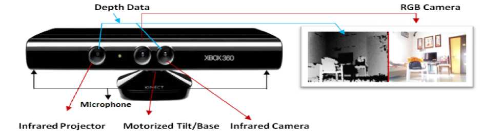
Fig.1. Microsoft Kinect XBOX 360 sensor with RGB and Depth sequence
Fig. 1 shows the arrangement of a Kinect sensor, consisting of an infrared (IR) projector, an IR camera, and a color camera. The depth sensor comprises the IR projector and the IR camera. The IR projector casts an IR speckle dot pattern into the 3-D scene while the IR camera captures the reflected IR speckles. Kinect is therefore an instance of a structured light depth sensor. The geometric relation between the IR projector and the IR camera is obtained through an off-line calibration procedure. The IR projects light speckle pattern into the 3-D view. The speckle is invisible to the color camera but can be viewed by the IR camera. Since each local pattern of projected dots is unique, matching between observed local dot patterns in the image with the calibrated projector dot patterns is feasible. The depth of a point can be deduced by the relative left-right translation of the dot pattern [6] [7] [8].
Table 1. Kinect Microsoft sensor specifications [1] [6]
|
Parameter |
Values |
|
Resolution of RGB/Depth/IR |
640 x 480 Pixel |
|
Depth Resolution (Default) |
2 - 40 mm |
|
Depth Range (Distance in meter) |
0.4 - 4.0 m |
|
Video Frame Rate (Frame per second) |
30 fps |
|
Motorized tilt range |
± 27̊ Vertical |
|
Field of view |
57̊ Horizontal, 43̊ Vertical |
|
Focal Length Depth |
5.453± 0.012 mm |
|
Focal Length Color |
4.884± 0.006 mm |
|
IR Wavelength |
830 nm |
|
Audio |
16 Bit, 16 KHz |
|
Power Supply |
USB+ACDC |
|
Size |
12” x 3” x2.5” |
|
Power Consumption |
12 watts |
-
III. Related work
There are few papers that related work implemented hardware or software of kinect. These literature surveys help us to design better system, advantages and limitation of the kinect sensor.
Xinchen Ye et al. [9] showed that multiview imaging with kinect proposed integrated depth color and depth image based frame work. Depth restoration from noisy data and view synthesis from depth color pairs are two major components. 2-Dimensional polynomial approximation is suppressed quantization error. To fill the missing areas of the depth map applied edge guided trilateral filter. Inpainting is applied to disocclusion area in view synthesis. The author is used augmented lagrange multiplier framework.
Li chen et al. [10] proposed region growing method to detect the wrong depth value and removed. Joint bilateral filter is applied to fill the holes. Adaptive bilateral filter is proposed to reduce the noise in kinect sensor.
Kinect camera capture real object image and construct 3D model based on surface texture mapping technique proposed Semih Dinc et al. [11]. Scale invariant feature transform, speeded up robot features, hough transform and least square optimization perform to construct textured 3D model of real object. The authors have chosen three objects with different sizes and shapes for observation.
Improved depth image-based rendering is used an adaptive compensation method on an autostereoscopic 3d display for a kinect sensor by chih hsien et al. [12]. The combination of color image and depth map is generated the autosteroscopic 3-D view. It is required to improve result to improve depth image-based rendering method. Depth map can be divided into blocks for statistical analysis and position of holes is allocated. The experimental results shows the enhance quality of depth map, filling holes and reduce computation time.
Din-Yuen Chan proposed kinect based stereo matching method to be used of the improved depth sequence. Author has applied SURF extraction scheme for featured matching. The stereoscopic camera and kinect sensor are used to generate disparity map based on stereo matching method for improved depth sequence. Bilateral filter, a hole filling and edge filtering process are applied in the kinect sensor [19].
Kinect sensor based basic algorithm and application introduced in this paper. J. Han describe the Kinect mechanism, specification, and software tool and performance evaluation to define the scheme of the object detection, tracking and recognition. It is also analysis of human various pose activity and hand gesture [7].
Depth restoration from noise depth map and view synthesis from depth-color pairs is obtained by X. Ye; J.Yamg et al. [20]. Re-demosicing and edge extractor perform from color image. Trilateral filter and depth dilation function are performed for depth restoration. For view synthesis warping and dis-occlusion filling is proposed. Depth image based rendering technique is used for completion of the task.
Akash bapatet al. [21] proposed the used for iterative median filter to improve quality of the kinect depth. Hole filling strategy to apply the depth data and to de-noise the depth which is applied for edge preserving filter and gets more accurate results.
-
IV. Proposed Work
The aim of the proposed system is to accept real time depth and 3-D map model from texture map. Depth is generated by the Kinect sensor as input and to produce a refined depth map as output. The holes filling, object boundary rectified and aligned pixel with color image is the vision of refinement of depth map [13]. To accomplish our goal we proposed some step for refinement and 3-D model from mapped surface shown in fig. 2. First image registration also called depth video preprocessing. Next step is depth refurbishment as frequency domain environment and morphological permutation to improve smoothness and correct the boundaries of the object in sequence. Depth holes filling and enhancement are done by the combination of spatial 2-D filtering and filling holes operation with random noise removal. The warping operation is applied to generate 3-D model from texture map surface at the end of the stage. The proposed real time depth refined work flow is shown in fig. 2 [14].
The output of kinect is color video and depth sequence is processed for registration and pre-processing. The size of output image is 640x480 pixels shown in table 1. The proposed experimental setup the numbers of frame acquired from kinect sensor are 300 both for color and depth sequence shown in fig. 3. Resize and number of frame sequence function are required for filtering process and refurbishment operation.
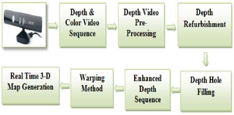
Fig.2. Flow of real time refined depth map and 3-D model
The permutation of morphological operators are dilation, erosion, opening and closing operation with structuring element neighborhood with specific matrix 0’s and 1’s. Morphological operator a dilation operation enlarges a region, while erosion reduces the size. A closing operation can close up internal holes in a region and smooth the contours of image. An opening operator removes the regions of an image that can’t contain structuring element. The mathematical equations are given below.
D (j, k) = P (j, k) Ф Q (j, k) = {z/(Bz)nA*0} (1)
E (j, k) = P (j, k) 0 Q (j, k) = (z/(B)zcA)
O (j, k) = P (j, k) o Q (j, k)
= {(P (j, k) Θ Q (j, k)) ⊕ Q (j, k)}(3)
C (j, k) = P (j, k) • Q (j, k)
= {(P (j, k) ⊕ Q (j, k)) Θ Q (j, k)}(4)
Where, P (j, k) = Image, Q (j, k) = Neighborhood element, D, E, O, C = Dilation, Erosion, Opening and closing operation respectively.
The different size and shape of structuring elements are rectangle, box, circular, disk and random. The function of the structuring elements is interacting with image. Central pixel of a symmetric structuring element may be denoted as its origin or any. Through reference point, translate the structuring element can be placed anywhere on the image. It can be applied to the image to enlarge or reduce a region, shape etc. Morphological opening operation remove thin protrusions, smooth object, break thin bond and removes regions cannot control the structuring element. Morphological closing operation smoothens the objects same as opening operator. Closing operator join the narrow breaks, fill hole smaller than structuring element and fill long thin gulf. In structuring element if we put number of 1’s in right side with dilation operation, the object’s region is enlarged, whereas in erosion same operation reduces the object boundary. In our algorithm we have used random structure [1 1 0; 0 1 0; 0 0 1] and [1 1; 0 0] etc.
The pseudo code of depth map and 3-D map is given in algorithm 1. Depth refurbishment pseudo code is given in algorithm 2.The output of the spatial filtering is processed for frequency domain.
The filtering process carried out in frequency domain using Fast Fourier Transform (FFT). FFT is flexible to design and implementation of filtering. Smoothing in frequency domain is attenuating a specific range of high frequency component in the image. Frequency domain filtering step is customized for transforming an image through filtering function and obtaining inverse transformed output. The input image is converted to 2-diamensional Discrete Fourier Transform (DFT). The DFT is calculated with a FFT algorithm. The component of the frequency domain is shift zero-frequency component to middle of spectrum. The 2-D DFT of f (u, v) is shown in eq. (5)
F(u,v)= X^^^y f(x,y)e "2 "(H)
Where u, v= 0, 1, 2, 3…M-1 and v, y= 0, 1, 2…N-1.
The filter function H (u, v) is multiplied of F (u, v) shown in eq. (6). F (u, v) is real and imaginary parts.
G (u, v) = H (u, v) F (u, v)(6)
Where H (u, v) the Gaussian transfer function is applied shown in eq. (7)
H (u,v)=e~D(^),/2 202
a is the standard deviation measure spread gaussian curve. We put a = D0 , the expression is shown in eq. (8)
H (u,v)=e~D (^'У22 2 D 02(8)
Where D 0 = cutoff frequency. Filter is down to 0.607 to maximum. The distance from any point to the origin of the Fourier transform is given in eq. (9)
D (u, v) = {(u-M/2)2 + (v-N/2)2}1/2(9)
D (u, v) is the distance from the origin of the Fourier Transform. The output of the filter function to apply 2-D Inverse DFT of f(x, y) is shown below eq. (10)
f (X,^ = (Me2 2 " M ■ ,
The use of Gaussian filters function no ringing effect is produce. Cut off frequency increase the image output is smoother. The proposed method are used the value of cut off frequency at three radii of 90, 190 and 250. Results are more suitable and smooth when the radii increased.
Filling stage is the key part of our method and completed the better result at post processing stage. Mathematical morphology operation is used as a tool to extract image components. These are useful in the description and representation of region shapes. Region filling operation is based on a set of dilations; complementation and intersections to fill the holes in the grayscale image. ‘ I ’ is the region or more connected components. We form an array X k the same size as the array containing ‘ I ’ whose elements are zeros
(background values), except at each location known to correspond to a point in each connected component in I , which we set to one (foreground value). The purpose is to start with X 0 and find all the connected components by the following iterative procedure in equation (11)
X k = (X k-J ® B) n Ic, k= 1, 2, 3^ (11)
Where B is structuring element, the procedure terminates when Xk = Xk-1 with Xk containing all the connected components of I .
Non-linear spatial filter also called as rank filter is performed to reduce the noise and this improves the output of the depth as a grayscale image is applied at the end of the stage. Median or order statistic filter is applied with size of mask 3, 7, 9, 11 etc.
Warping method is used to display gray scale, color, binary, intensity and indexed image as texture-mapped rectangular surface. Texture mapping is a process that maps an image onto a surface grid using bilinear interpolation. It is a method for adding details of images, 3-D model or mapped pixels from texture to a 3-D surface [11].
-
V. Parameter for Image Quality Assessment
We evaluated the performance of proposed stereo matching algorithm with JBU, WMF, SAD, SHD and SSD methods [15] [16] [17] [18]. The results of the
Algorithm 1 Depth map and 3-Dimensional model
Input: Frame sequence
Output: Real timedepth and 3 D model
---------------------------------------------------------------------
Ӻ D , Ӻ C - depth and color frame acquired
N - number of frame
Đ, ɛ, ʗ, ȍ - dilation, erosion, closing, opening
ɱ Đ , ɱ ɛ , ɱ ʗ , ɱ ȍ - dilated, eroded, closed and opened results respectively
ᶘ C , ᶘ D - color and depth image
Š e - structuring value
Ǒ d - order statistic 2-dimentional image operation ḟ od - order statistic output
ɖ ref , ɖ refo - depth refurbishment operation and output respectively Ӈ f , Ӈ fo - holes filling operation and output respectively
ɯ - warping operation start ([ӺD, ӺC])
ɱ Đ = Đ (ᶘ D , Š e ), ɱ ɛ = ɛ (ɱ Đ , Š e ) ɱ ʗ = ʗ (ɱ ɛ , Š e ), ɱ ȍ = ȍ (ɱ ʗ , Š e )
ḟ od = Ǒ d (ɱ ȍ , order, domain)
ɖ refo = ɖ ref (ḟ od ) (see the algorithm - 2)
Ӈfo= Ӈf (ɖrefo, Ӈ) ɯ = (ӺC, Ӈfo) end stop(ӺD)
stop (Ӻ C )
catch stop(ӺD)
stop(Ӻ C )
end
Algorithm 2 Depth refurbishment
Input: Preprocessed frame sequence
Output: Depth refined frame sequence
Ŧ top , Ŧ to , Ŧ sft , Ŧ sftop – Fourier transformed output, operation, component shift to the center of spectrum and centered frequency component output respectively
IŦ to – inverse fourier transform operation
Ŧ c , Ŧ cop – center the frequency operation and output
ḟ od - order statistic output
ᶃ o , ᶃ op - gaussian operation and output
Ȼ - convolution, m, n - row and column
ɖ refo - depth refurbishment output
Ŧ top
= Ŧ to (ḟ od )
Ŧsftop = Ŧsft (Ŧtop) for s= 1: m for t= 1: n
Ŧ cop = Ŧ c (s, t)
ᶃo p = ᶃ(Ŧco p )
end end
Ȼ = Ŧ sftop. *ᶃ op ɖ refo = abs(IŦ to (Ȼ))
proposed algorithms are evaluated with structural similarity (SSIM) index and PSNR (peak signal-to-noise ratio) and Mean Square Error (MSE).
The Structural Similarity Index Map (SSIM) is a reference metric measuring image quality based on ground truth. The SSIM index measures the similarity between two images. It computes three terms (a) luminance term (b) contrast term (c) structural term shown in eq. (12)
SSIM (S,t)= штк)Мк)У (12)
Where,
(kj + l4 + ci )
c (j,k) =
(2OjOk + c2) (°2 + ak + c2)
s (j,k) =
( О] к + c3)
(ojOk + c3 )
SSIM (j ,k)=^№^2i^
W * I1 к +c i )( aj + ak +c 2 )
Peak Signal to Noise Ratio (PSNR) measure of quality measurement between the ground truth and a resultant image shown in the mathematical eq. (14),
PSNR (k,n = (m*n)10 log, 0 ^ (14)
Mean Square Error (MSE) mean squared difference between the reference image and resultant image. It is the Euclidian distance between the reference image and the resultant images. The MSE mathematical derived by eq. (15)
MSE = ^M,N\k( i, j )-k(iJ)i2 (15)
Where M and N are the number of rows and columns respectively;“R” is the number of image gray levels. PSNR calculates the peak signal to noise ratio in decibels (dB) between ground truth and resultant images. The higher the PSNR, the enhanced the qualities of the disparity map [22].
-
VI. Results and Discussion
The experimental setup for this research depicted in fig. 3 shows the depth measure of the object. This depth is measured for different objects located at different distances. Table 2 shows the different objects location with respect to Kinect sensor.
Table 3 shows the values of all qualitative parameters of a video frame captured by kinect using proposed algorithm. To check the performance of this research method to capture the depth sequence at 4, 3.5, and 3 meter distance is shown in table 3. As the kinect sensor has maximum range of near about 4 meter, we have computed various parameter values for 3, 3.5 and 4 meter distance. Results show that the optimum results are obtained at a distance 3.5 meter. The object set various size and shape; therefore, we can prove the efficiency of proposed algorithm. The proposed method are used the value of cut off frequency at three radii of 90, 190 and 250. The value of PSNR and SSIM of the resultant image is increased when the cut off frequency radii value increases. The value of MSE of the resultant image is decreased as the value of radii increases. Therefore, it is
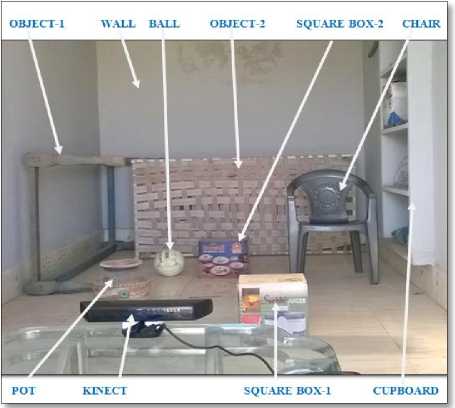
Fig.3. Experimental setup for different size of objects and located at different distance
increasing the cut off frequency smoothness the image output. Results are more suitable and smoother when the radii are increased. The values of SSIM, PSNR are gain at the set of radii is 250 because most of the information in the image will be covered in the output image shown in table 3 at the distance 3.5 meter. MSE is also decreased at the value of radii 250. Gaussian low pass filter has an ability to pass low frequency component and it will block the higher frequency component. Here, we have chosen three different cut off frequencies for filtering the image. Table 3 shows that for lower cut off frequency, the value of statistical parameters are very low because the pass band is very low. Table 3 also shows that as the cut off frequency increases, the processed image contains more information and this leads to better values of SSIM, PSNR and MSE.
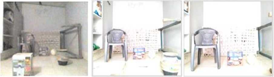
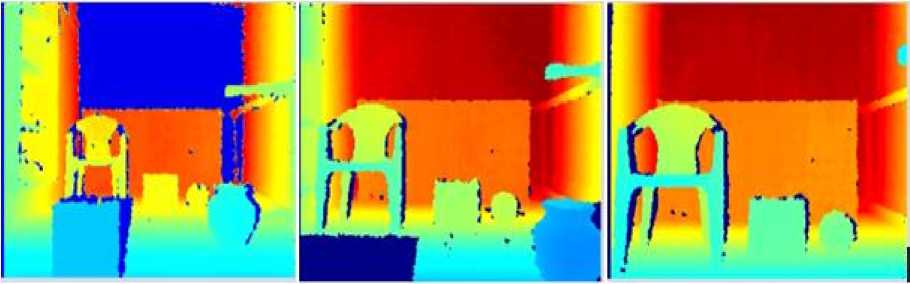
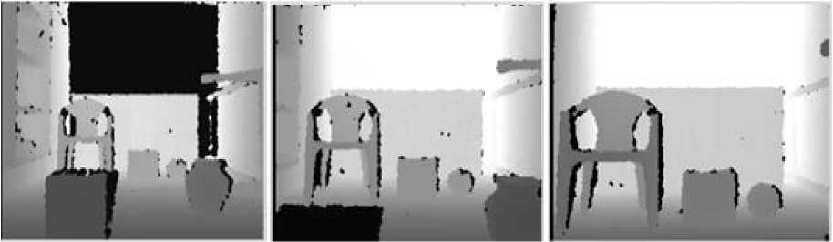
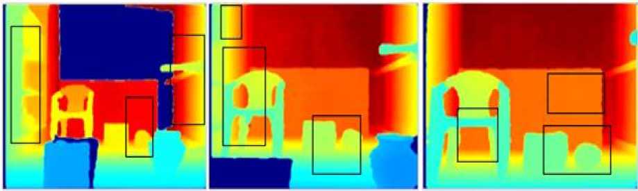
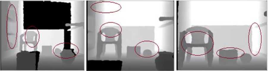
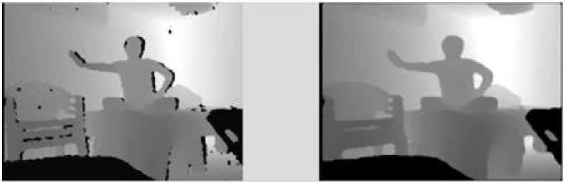
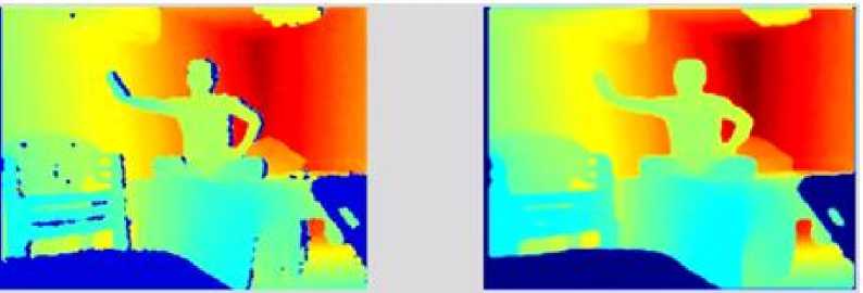
Fig. 4 shows the color camera sequence and the object location from 4, 3.5 and 3 meter distance captured by kinect sensor. Fig. 5 shows the color raw depth frame sequence and the object location from 4, 3.5 and 3 meter distance captured by kinect sensor. Fig. 6 shows the gray scale raw depth frame sequence and the object location from 4, 3.5 and 3 meter distance captured by kinect sensor. The results of color refined depth frame shown in fig. 7. In fig. 7 shows the boxes represents the ability of the remove noise and filling holes. The results of gray scale refined depth frame shown in fig. 8. In fig. 8 shows the red oval represents the ability of the remove noise and filling holes. Fig. 7 and 8 the results are representing the ability to refine the edges and work in dark region. Fig. 9(a) shows the gray raw depth and 9(b) shows refined depth sequences.
(a) (b) (c)
Fig.4. Color camera sequence captured by Kinect (a) 4 m (b) 3.5 m (c) 3 m
(a) (b) (c)
Fig.5. Color raw depth sequence captured by Kinect (a) 4 m (b) 3.5 m (c) 3 m
(a) (b) (c)
Fig.6. Gray scale raw depth sequence captured by Kinect (a) 4 m (b) 3.5 m (c) 3 m
(a) (b) (c)
Fig.7. Results of color refined depth sequence (a) 4 m (b) 3.5 m (c) 3 m
(a) (b) (c)
Fig.8. Results of raw gray scale refined depth sequence (a) 4 m (b) 3.5 m (c) 3 m
(a)
(b)
Fig.9. Results of gray scale raw depth and refined frame sequences.
(b)
Fig.10. Results of color raw depth and refined frame sequences.
(a)
(b)
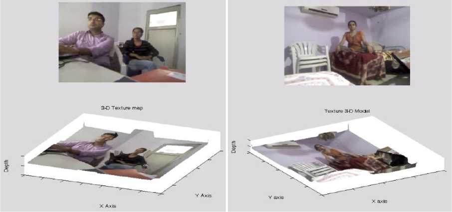
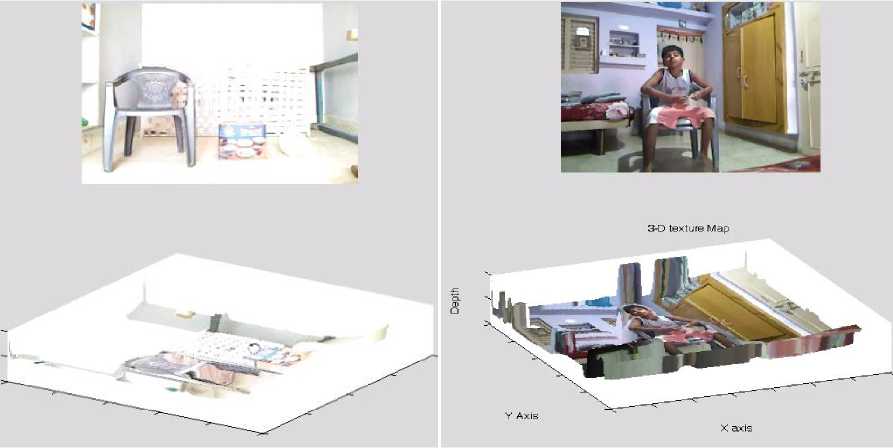
Fig.11. Results of texture maping 3-D modeling by proposed algorithm
(a)
(b)
Fig.12. Results of texture maping 3-D modeling by proposed algorithm
Table.2. Objects location with respect to Kinect sensor
|
Sr. No. |
Different object size and shape |
Distance from Kinect (Meter) |
|
1 |
Square Box-1 |
1 |
|
2 |
Pot |
1.5 |
|
3 |
Cupboard |
2 |
|
4 |
Object-1 |
2.2 |
|
5 |
Chair |
2.3 |
|
6 |
Square Box-2 |
2.5 |
|
7 |
Ball |
2.6 |
|
8 |
Object-2 |
3.5 |
|
9 |
Wall |
4 |
Table.3. Quality assessments reading of the frame sequence captured by kinect
|
Distance from Kinect (Meter) |
Cut off frequency at radii value |
SSIM |
MSE |
PSNR |
|
4 M |
90 |
0.8414 |
0.0093 |
68.44 |
|
190 |
0.8979 |
0.0026 |
74.02 |
|
|
250 |
0.8983 |
0.0024 |
74.27 |
|
|
3.5 M |
90 |
0.8633 |
0.0099 |
68.16 |
|
190 |
0.9311 |
0.0015 |
76.32 |
|
|
250 |
0.9331 |
0.0012 |
77.49 |
|
|
3 M |
90 |
0.8414 |
0.0093 |
68.43 |
|
190 |
0.8979 |
0.0026 |
74.01 |
|
|
250 |
0.8983 |
0.0024 |
74.40 |
We can observe that the proposed method produce more accurately recovered local details of the contours. We also observed that the contours of the sequences are smoother and aligned. Fig. 10(a) shows the color raw depth sequences and 10(b) shows the refined depth sequences. In fig. 10(b) we observed that the contours of the sequences are smoother and aligned with color sequences. The accurate hole-filling is done by the hole filling operation. The speed of the proposed algorithm varies with the number of invalid pixel and number of acquired frame. The average computational time is 35 second per 300 frames. The approximate time of one frame is 0.11 sec/frame.
The warping method is generated texture 3-D model by combination of color frame and final refined depth map shown in fig. 11 and 12. The proposed method are generating visibly clear and accurate fill the hole in texture model. There is not a major distortion on the texture in 3-D model. The real time texture 3-D model is rotated to show the issues of the outlook. The 3-D map is noticeably visible that the most of portion of the model is properly generated [11].
The proposed algorithm has provided an efficient result to improve depth map by filling holes, removing wrong value pels and noise. These all are improved by applied morphological permutation operation, 2D spatial domain filtering, depth refurbishment in Fast Fourier Transform (FFT) operation and holes filling operation.
-
VII. Conclusion
MatLab has been chosen for implementing the proposed algorithm. The specifications of our PC areas Intel Core i3-3227U CPU with 1.90 GHz working frequency, 4 GB RAM. Our results show that this proposed algorithm displays quite better depth map than other algorithms. However, our algorithm displays better values of PSNR than reported algorithm. Our proposed algorithm provides an efficient result to improve depth map by filling holes, removing wrong value pels and noise. These all are improved by applied morphological permutation operation, 2D spatial domain filtering, depth refurbishment in frequency domain operation and holes filling operation. Experimental results show that the proposed method significantly improves the quality of depth image successfully by depth data refurbishment, filling the holes, eliminating the unmatched edges and reducing the noise. This post-processing technique corrects and sharpens the boundaries of the objects of the depth map and ensures local depth smoothness within the objects. In all of the proposed techniques, an effort is made to reduce the complexity. This algorithm is executed 3D texture map in real-time. Experimental results show that the random error of depth measurement increases when the distance between the scene and the sensor increases, ranging from a few millimeters at close range to about 4 M at the maximum range of the sensor. There are many applications in computer vision such as skeleton tracking, pose estimation, 3-D reconstruction and gesture recognition in which depth map captured by
kinect is used. This research work presented here is useful of computer vision application with RGB-D sensor. The improved quality of depth maps and texture mapping 3-D modeling expands the application of kinect where high quality depth sequences are mandatory.
Acknolodgement
References Real Time Depth Data Refurbishment in Frequency Domain and 3D Modeling Map Using Microsoft Kinect Sensor
- Ling Shao, "Computer Vision for RGB-D Sensors: Kinect and Its Applications", IEEE Transactions On Cybernetics, Vol. 43, No. 5, October 2013.
- J. Smisek, M. Jancosek, and T. Pajdla, "3-D with Kinect," in Proc. IEEE ICCV Workshops, 2011, pp. 1154–1160.
- J. Geng, "Structured-light 3-D surface imaging: A tutorial," Adv. Optics Photonics, vol. 3, no. 2, pp. 128–160, 2011.
- I. Tashev, "Recent advances in human-machine interfaces for gaming and entertainment," Int. J. Inform. Technol. Security, vol. 3, no. 3, pp. 69–76, 2011.
- K. Kumatani, T. Arakawa, K. Yamamoto, J. McDonough, B. Raj, R. Singh, and I. Tashev, "Microphone array processing for distant speech recognition: Towards real-world deployment," in Proc. APSIPA Annu. Summit Conf., 2012, pp. 1–10.
- T. Mallick, "Characterizations of Noise in Kinect Depth Images: A Review," IEEE Sensors Journal, VOL. 14, NO. 6, pp. 1731-1740, 2014.
- Jungong Han, "Enhanced Computer Vision with Microsoft Kinect Sensor: A Review," IEEE Transactions On Cybernetics, Vol. 43, No. 5, pp. 1318-1334, 2013.
- http://www.xbox.com/en-US/kinect/default.htm, Kinect Camera [online].
- Xinchen Ye, Jingyu Yang, "Computational Multi-View Imaging with Kinect," IEEE Transactions On Broadcasting, Vol. 60, No. 3, pp. 540-554, September 2014.
- Li Chen, Hui Lin, "Depth Image Enhancement for Kinect Using Region Growing and Bilateral Filter," ICPR 2012, 978-4-9906441-1-6 pp. 3070-3073, IAPR, Tsukuba, Japan, 2012.
- M. Sigdel, "Depth-Color Image Registration for 3D Surface Texture Construction using Kinect Camera System," 978-1-4799-6585-4, IEEE, 2014.
- Chih-Hsien Hsia, "Improved Depth Image-Based Rendering Using an Adaptive Compensation Method on an Autostereoscopic 3-D Display for a Kinect Sensor," IEEE Sensors Journal, Vol. 15, No. 2, pp. 994-1002, Feb 2015.
- Na-Eun Yang, Yong-Gon Kim, "Depth Hole Filling Using the Depth Distribution of Neighboring Regions of Depth Holes in the Kinect Sensor," 978-1-4673-2193-8,pp. 658-661, IEEE, 2012.
- K. Rao, Joohee Kim, "Refinement of Depth Maps Generated By Low-Cost Depth Sensors," 978-1-4673-2990-3, pp. 355-358, ISOCC, IEEE, 2012.
- K. Khoshelham and S. Elberink, "Accuracy and resolution of Kinect depth data for indoor mapping applications," Sensors, vol. 12, no. 2, pp. 1437–1454, 2012.
- Yatong Xu, Xin Jin,"Spatial-temporal Depth De-noising for Kinect based on Texture Edge-assisted Depth Classification," IEEE, ICDSP, 978-1-4799-4612-9, pp. 327-332, 2014.
- Ashish M. Kothari,Ved Vyas Dwivedi, "Hybridization of DCT and SVD in the Implementation and Performance Analysis of Video Watermarking," International Journal of Image, Graphics and Signal Processing (IJIGSP), Print: ISSN 2074-9074 & Online: ISSN 2074-9082,2012
- Jinhui Hu," Kinect depth map based enhancement for low light surveillance image," IEEE, pp. 1090-1094, 978-1-4799-2341-0, 2013.
- Din-Yuen Chan, Che-Han Hsu Regular, "Stereo Matching Improvement System Based on Kinect-supporting Mechanism,"Scientific research, Open journal of applied science, 3, page 22-26 2013.
- X. Ye; J.Yamg; Hao Huang; ChunpingHou; and Yao Wang, "Computational multiview imaging with Kinect," IEEE transactions on broadcasting, Vol. 60, Issue 3, Pages: 540 – 554, 2014.
- Akash Bapat,"An iterative, non-local approach for restoring depth maps in RGB-D images,"IEEE Conference on Communications (NCC), 2015 Twenty First National, Pages: 1-6, 2015.
- Ashish M. Kothari, Ved Vyas Dwivedi, "Video Watermarking – Embedding binary watermark into the digital video using hybridization of three transforms," International Journal of Signal and Image Processing Issues Vol. 2015, no. 1, pp. 9-17 ISSN: 2458-6498.
