Recent Advances of Distributed Optical Fiber Raman Amplifiers in Ultra Wide Wavelength Division Multiplexing Telecommunication Networks

Author: Abd El–Naser A. Mohamed, Ahmed Nabih Zaki Rashed, Mahmoud M. A. Eid
Journal: International Journal of Computer Network and Information Security(IJCNIS) @ijcnis
Article in issue: 4 vol.4, 2012.
Free access
Recently, many research works have been focused on the fiber optic devices for optical communication systems. One of the main interests is on the optical amplifiers to boost a weak signal in the communication systems. In order to overcome the limitations imposed by electrical regeneration, a means of optical amplification was sought. The competing technology emerged: the first was Raman amplification. One reason was that the optical pump powers required for Raman amplification were significantly higher than that for Erbium doped fiber amplifier (EDFA), and the pump laser technology could not reliably deliver the required powers. However, with the improvement of pump laser technology Raman amplification is now an important means of expanding span transmission reach and capacity. We have deeply studied an analytical model for optical distributed Raman amplifiers (DRAs) in the transmission signal power and pump power within Raman amplification technique in co-pumped, counter-pumped, and bi-directional pumping direction configurations through different types of fiber cable media. The validity of this model was confirmed by using experimental data and numerical simulations.
Distributed Raman amplifier, Fiber link media, Signal power, Pump power, Raman gain efficiency
Short address: https://sciup.org/15011078
IDR: 15011078
Text of the scientific article Recent Advances of Distributed Optical Fiber Raman Amplifiers in Ultra Wide Wavelength Division Multiplexing Telecommunication Networks
Published Online May 2012 in MECS
Optical transmission system design issues such as mid span optically amplified distance, bandwidth enhancement can be assisted using Raman optical amplification (ROA) technology. ROA does not suffer from the limitations of EDFA in that it can be integrated with the transmission fibers, and pumped at any wavelength to provide wide gain bandwidth and gain flatness by employing a combination of different wavelength pumping sources. Different pumping configurations provide flexibility in the system for both distributed and discrete ROA. Only recently has ROA technology in transmission of optical signals become an achievable possibility, it offers a number of possible technical advancements to optically amplified long haul transmission infrastructure. Recently, there have been many efforts to utilize fiber Raman amplifier (FRA) in long-distance, high-capacity WDM systems [1]. This is mainly because FRA can improve the optical signal-to-noise ratios and reduce the impacts of fiber nonlinearities [2].
In modern long haul fiber-optic communication systems, the transmission distance is limited by fiber loss and dispersion. Traditional methods to overcome this limitation, which use electrical conversion of the optical signal [3], such as repeaters to retransmit signals at progressive stages are becoming increasingly complex and expensive. In the 1990's, optical amplifiers, which directly amplified the transmission signal, became widespread minimizing system intricacies and cost. While upgrades in transmission fiber design in particular dispersion compensating fibers (DCF) minimized linear phase distortions in the signal. In modern systems, existing EDFA lumped optical amplifiers are employed to ensure the quality of the transmitted signals. SRS has become important in the application of optical amplification because of several important reasons in comparison to other similar methods. ROA can be described simply as a pump laser which emits light waves down an optical fiber; this signifies that it can be compatible with most available transmission systems. The operation of the pump laser is dependant upon the gain that is achieved, in particular the pump wavelength. This means that the medium of transmission is completely independent, in contrast to the lumped optical amplification type, the Erbium-Doped Fiber Amplification (EDFA). The fact that the gain is pump wavelength dependent theoretically means that amplification is achievable for any frequency [4]. It is important to note that utilizing a number of lasers at variable frequencies in a system will provide a broad gain bandwidth. There are also advantages to ROA from EDFA in low noise characteristics, which can improve the overall signal quality [5].
In the present study, we have deeply analyzed the signal power, pumping power, rate of change of signal, pumping powers with respect to transmission distance under the variations of signal, pump powers and signal and pump wavelengths for different fiber link media in different pumping direction configurations (forward, backward, and bi-directional) over wide range of the affecting parameters.
-
II. Basic Multiplexing/Demultiplexing Based Distributed Optical Raman Amplifier
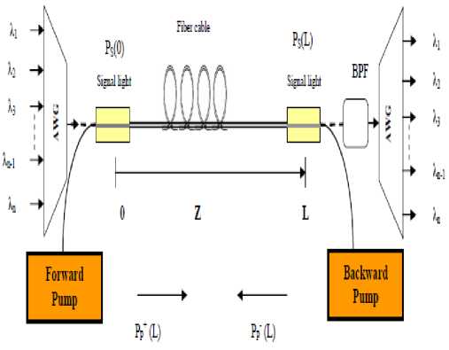
Fig. a. Schematic view of multiplexing/demultiplexing based distributed optical Raman amplifier.
Figure (a) is a schematic showing the configuration of multiplexing/demultiplexing based fiber distributed Raman amplifier. It is provided with arrayed waveguide grating (AWG) devices which acts as multiplexing unit in the transmitting side. Basically, pumping light and signal light are input to a single amplifier fiber and amplification is effected by means of the stimulated scattering that occurs in the fiber [6]. Fig. (a), shows a configuration in which pumping light propagates bidirectionally in the Raman amplifier fiber, but in some it propagates in the same direction as the light signal (forward pumping) or the opposite direction (backward pumping). Moreover the system is provided with band pass filter (BPF) and AWG devices which acts as demultiplexing unit in the receiving side. Generally, speaking with forward pumping the signal to noise ratio (SNR) can be kept high, while with backward pumping the saturation output power can be increased. In the case of a Raman amplifier the process of optical amplification takes place so rapidly that, unless the intensity noise of the forward pumping light is sufficiently small, the pumping light noise will be transferred to the signal light resulting in increasing transmission bit error rates. Thus in many cases only backward pumping is used [7].
-
III. Model and Equations Analysis
The evolution of the input signal power (P s ) and the input Pump Power (P p ) propagating along the single mode optical fiber in watt, can be quantitatively described by different equations called propagation equations. The signal and pump power can be expressed as [8]:
dP P- = -« Lp P p ( Z ) - "f g R P s ( Z ) P p ( Z )
dz ^ p A eff
P = -« LsPs ( z ) + 4^ gT" Ps ( z ) Pp ( z ) (2) dz 4 P A eff
Where g R is the maximum Raman gain in km W-1, g Reff is the Raman gain efficiency in W-1km-1 of the fiber cable length L in km, λ s and λ p are the signal and pump wavelengths in km, A eff the effective area of the fiber cable used in the amplification in km2 ,z is distance in km from z=0 to z=L, a Ls and a Lp are the linear attenuation coefficient of the signal and pump power in the used optical fiber in km-1, The linear attenuation can be expressed as [9]:
a L = a /4.343
PPF ( z ) = P poF ex P (- « LP z ) (4)
Where P PoF is the input pump power in the forward direction in watt at z=0. In the backward pumping the pump power is respectively equal to:
PPB ( z ) = PpoB e xP [ - a LP ( L - z )] (5)
Where P PoB is the input pump power in the backward direction in watt at z=L. In the case of a bi-directional pump both of the pump can be equal or different in the used wavelength or the used power [10]. Therefore to calculate the pump power at point z it can be used:
PPFB ( z ) = ( r ) PpoF ex P ( - a LPZ M1 - r ) PpoB ex P [ - a LP ( L - z )] (6)
If the values of P P are substituted in differential Eq. (2), and it is integrated from z=0 to z=L for the signal power in the forward and the backward pumping can be:
PS ( z ) = Pso e xP
" gR- I A eff
PpoLeff - a SLZ
Where L eff , is the effective length in km, over which the nonlinearities still holds or stimulated Raman scattering (SRS) occurs in the fiber and is defined as [11]:
_ 1- exp (-a PLZ )
Leff =--------------- « PL
Recently, there have been many efforts to utilize fiber Raman amplifier (FRA) in long-distance, high-capacity WDM systems. This is mainly because FRA can improve the optical signal-to-noise ratios and reduce the impacts of fiber nonlinearities [12].
-
IV. Simulation Results and Performance Analysis
In the present study, the optical distributed Raman amplifiers have been modeled and have been parametrically investigated, based on the coupled differential equations of first order, and also based on the set of the assumed of affecting operating parameters on the system model. In fact, the employed software computed the variables under the following operating parameters as shown in Table 1.
Table1. Typical values of operating parameters in proposed model.
|
Operating parameter |
Symbol |
Value |
|
Operating signal wavelength |
λ s |
1.45 ≤ λ s , µm ≤ 1.65 |
|
Operating pump wavelength |
λ p |
1.40 ≤ λ p , µm ≤ 1.44 |
|
Input signal power |
P so |
0.002 ≤ P so , W ≤ 0.02 |
|
Input pump power |
P po |
0.165≤ P po , W ≤ 1.75 |
|
Effective Area |
A eff |
55 – 72 – 84.95 (µm) 2 |
|
Raman Gain Efficiency |
g Reff |
0.6 – 0.45 – 0.38 (W.km)-1 |
|
Percentage of power launched in forward direction |
rf |
0.5 |
|
Attenuation of the signal power in silica-doped fiber |
α S |
0.25 dB/km |
|
Attenuation of the pump power in silica-doped fiber |
α P |
0.3 dB/km |
The following points of discussion will cover all operating design parameters of multiplexing/demultiplexing based optical distributed Raman amplifier device, such as, input signal power, input pumping power, operating signal wavelength, operating pump wavelength, and different fiber link media. Then based on the basic model analysis and the set of the series of the following figures are shown below, the following facts can be obtained:
-
IV. 1. Variations of the output signal power
Variations of the output signal power, P s is investigated against variations of the controlling set of parameters as displayed in Figs. (1-4). These figures clarify the following results:
-
i .As distance z increases, the output signal power decreases exponentially in case of forward and backward pumping cases, but in case of bidirectional pumping , after the output signal power decreases exponentially until it reach near z=50km it increases exponentially.
-
ii. For certain value of distance z, the output signal power in case of bi-directional pump is greater than the other pumping configurations.
-
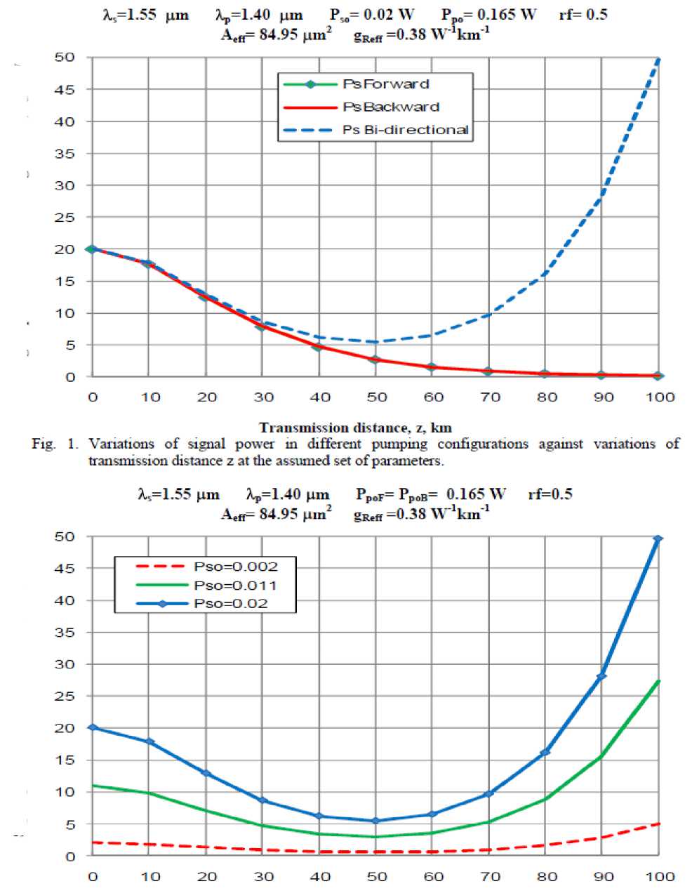
iii. With increasing the initial signal power, the output signal power will increase.
-
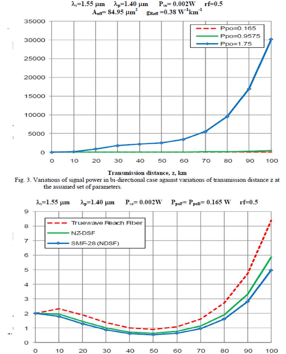
iv. With increasing the initial pumping power, the output signal power will increase.
-
v. After using different media of optical fiber cable, it is indicated that the true wave reach fiber presented the best results.
-
IV. 2. Variations of the output pumping power
Variations of the output pumping power, P p is investigated against variations of the controlling set of parameters as displayed in Figs. (5-6). These figures clarify the following results:
-
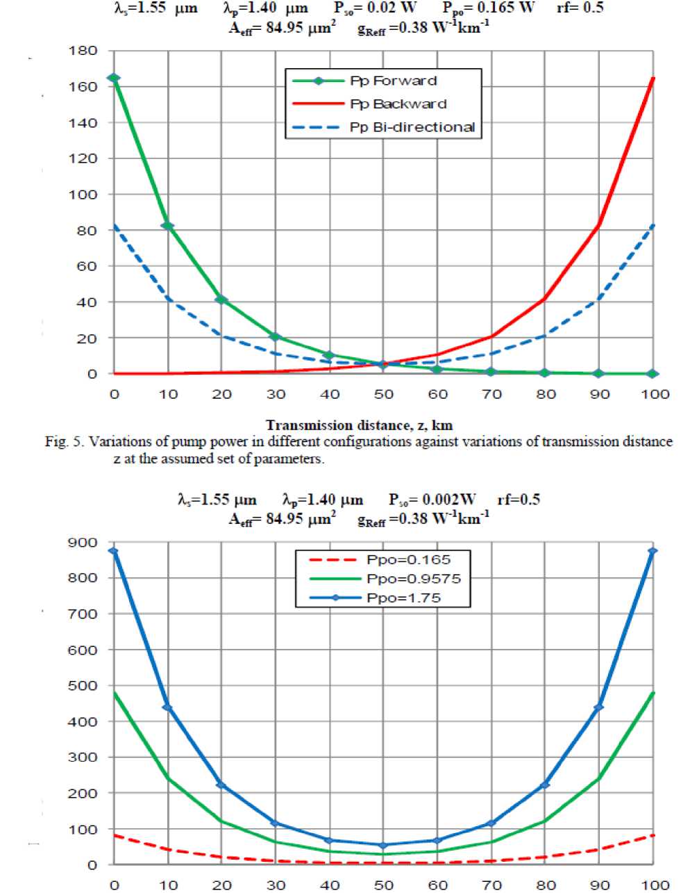
i. As distance z increases, the output pumping power decreases exponentially in case of forward and backward pumping cases, but in case of bidirectional pumping , the output pumping power is equal to the product of the forward and backward direction configuration.
-
ii. For certain value of distance z, with increasing the initial pumping power, the output pumping power will increase.
-
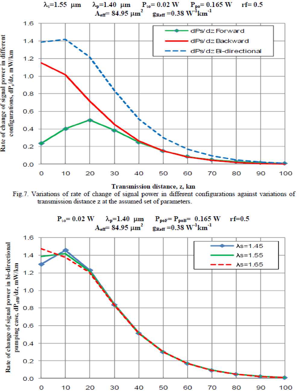
IV. 3. Variations of rate of change of signal power
Variations of the rate of change of signal power, dP s /dz is investigated against variations of the controlling set of parameters as displayed in Fig. (7). This figure clarify the following results:
-
a) In case of forward pump: As distance z increases, the rate of change of signal power increases linearly until reach to z=20 km, after that it decreases exponentially.
-
b) In case of backward pump: As distance z increases, the rate of change of signal power decreases linearly until reach to z=10 km, after that it decreases exponentially.
-
c) In case of bi-directional pump: As distance z increases, the rate of change of signal power increases linearly until reach to z=10 km, for 10 < z, km < 20 it decreases, after that it decreases exponentially.
In general For certain value of distance z, the rate of change of signal power, dP s /dz in case of bi-directional pump is greater than the other pumping configurations.
Signal power in bi-directional case, P,ra, mW Signal power in different configurations, P„ mW
Transmission distance, z, km
Fig. 2. Variations of signal power in case of bi-directional case against variations of transmission distance z at die assumed set of parameters.
Signal power in bi-directional case, Р,щ, mW Signal power in bi-directional case, Р,щ, mW
Transmission distance, z, km
Fig. 4. Variations of signal power in bi-directional case against variations of transmission distance z at the assumed set of parameters.
Pump power in bi-directional case, Ppm< mW Pump power in different configurations, Pp, mW
Transmission distance, z. km
Fig. 6. Variations of pump power m bi-directional case against variations of transmission distance z at the assumed set of parameters.
Transmission distance, z, kmFig. 8. Variations of rate of change of signal power in bi-directional pumping case against variations of transmission distance z at the assumed set of parameters.
Transmission distance, z, kmFig. 10. Variations of rate of change of signal power in bi-directional pumping case against variations of transmission distance z at the assumed set of parameters.
Transmission distance, z, km.Fig. 12. Variations of rate of change of signal power in bi-directional pumping case against variations of transmission distance z at the assumed set of parameters.
Transmission distance, z, lan
Fig. 1-4. "Variations of rate of cliange of pump power in hi-directional pumping case against var iations of transmission distance z at the assumed set of parameters.
Transmission distance, z. kin
Fig. 15. Variations of rate of change of pump power in bi-directional case against variations of transmission distance z at the assumed set of parameters.
-
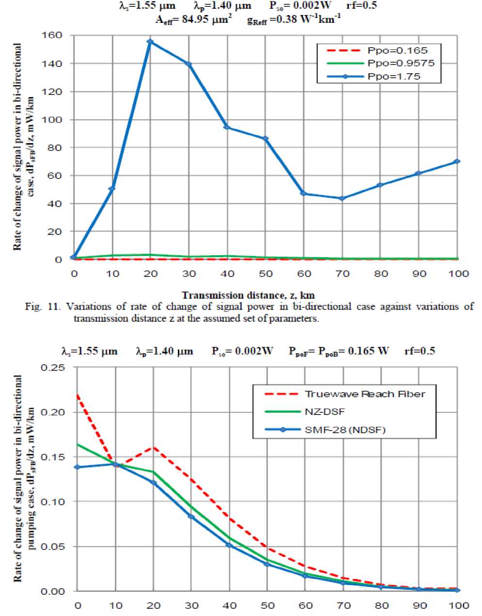
IV. 4. Variations of rate of change of signal power in case of bi-directional pump.
Variations of the rate of change of signal power in case of bi-directional pump, dP sFB /dz is investigated against variations of the controlling set of parameters as displayed in Figs. (8-12). These figures clarify the following results:
-
a) In case of varying the operating signal wavelength: At z=0, as the operating signal wavelength, λ s increases, the value of dP sFB /dz increases also until z ≈ 8 km, , for 8 < z, km < 30 with increasing λ s , there is significant decreasing in value of dP sFB /dz, after that there is slightly decreasing with increasing the wavelength.
-
b) In case of varying the operating pump wavelength: At z=0, as the operating pump wavelength, λ p increases, the value of dP sFB /dz decreases until z ≈ 8 km, , for 8 < z, km < 30 with increasing λ p , there is significant increasing in value of dP sFB /dz, after that there is slightly increasing with increasing the wavelength.
-
c) In case of varying the input signal power:
-
i. As distance z increases, the rate of change of signal power in bi-directional case, dP sFB /dz increases linearly until z ≈ 10 km, for 10 < z, km < 20 with increasing z , there is linear decreasing in the value of dP sFB /dz, after that it decreases exponentially.
-
ii. For certain value of distance z, with increasing the initial signal power, the value of dP sFB /dz also increases.
-
d) In case of varying the input pump power:
-
i. In general for each value of pumping power, there are three main intervals to study the variation of dP sFB /dz with z, in the first interval with increasing z, the rate of change of signal power in bidirectional case, dP sFB /dz increases also, in the second interval with increasing z, the rate of change of signal power in bi-directional case, dPsFB/dz decreasing, in the third interval with increasing z, the rate of change of signal power in bi-directional case, dP sFB /dz increases linearly.
-
ii. For certain value of distance z, with increasing the initial pump power, the value of dP sFB /dz also increases.
-
e) In case of varying the fiber link media:
The value of dP sFB /dz in case of using SMF-28 (NDSF) < the value of dP sFB /dz in case of using NZ-DSF < the value of dP sFB /dz in case of using truewave reach fiber.
-
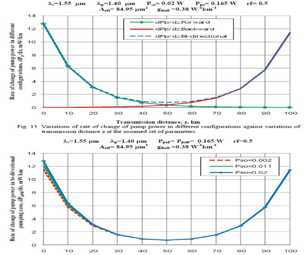
IV. 5. Variations of the rate of change of pump power in different configurations.
Variations of the rate of change of pump power in different configurations; dPp/dz is investigated against variations of the controlling set of parameters as displayed in Fig. (13). This figure clarifies the following results: As distance z increases, the rate of change of pump power decreases exponentially in case of forward and backward pumping cases, but in case of bi-directional pumping, the rate of change of pump power is equal to the product of the forward and backward direction configuration.
-
IV. 6. Variations of rate of change of pump power in case of bi-directional pump.
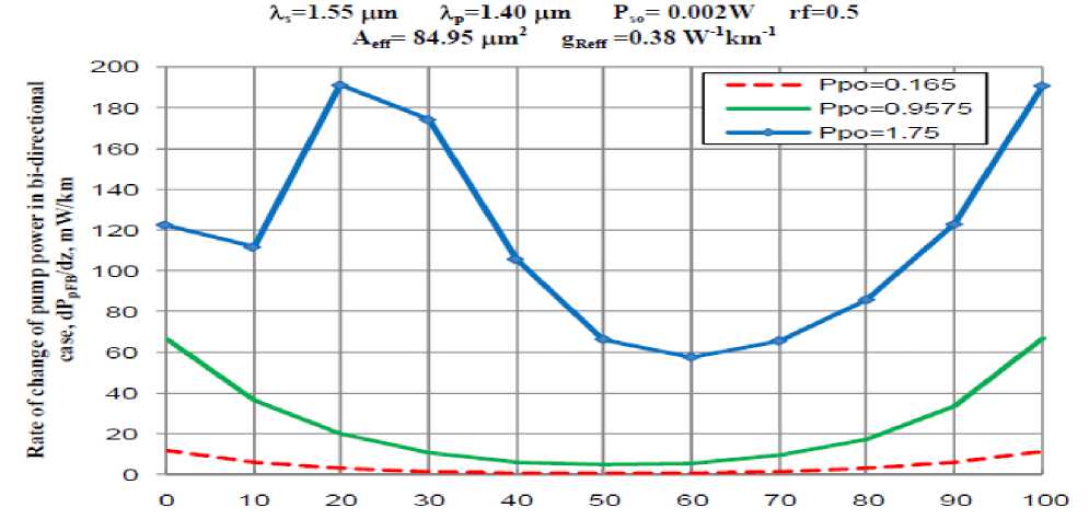
Variations of the rate of change of pump power in case of bi-directional pump, dP pFB /dz is investigated against variations of the controlling set of parameters as displayed in Figs. (14, 15). These figures clarify the following results:
-
a) In case of varying the input signal power:
-
i. As distance z increases, the rate of change of pump power in bi-directional case, dP pFB /dz decreases exponentially until z = 50 km, after that it
increases exponentially.
-
ii. For certain value of distance z, with increasing the initial signal power, the value of dP pFB /dz also increases.
-
b) In case of varying the input pump power:
-
i. For input pumping power = 1.75 W , there are three main intervals to study the variation of dP pFB /dz with z, in the first interval with increasing z, the rate of change of pump power in bi-directional case, dP pFB /dz decreases, in the second interval with increasing z, the rate of change of pump power in bi-directional case, dP pFB /dz decreases exponentially, in the third interval with increasing z, the rate of change of pump power in bi-directional case, dP pFB /dz increases exponentially.
-
ii. For input pumping power = 0.165 W or input pumping power = 0.9575 W , as distance z increases, the rate of change of pump power in bi-directional case, dP pFB /dz decreases
exponentially until z=50 km, after that it increases exponentially. As well as for certain value of distance z, with increasing the initial pump power, the value of dP pFB /dz also increases.
-
V. Conclusions
In a summary, we have deeply investigated multiplexing/demultiplexing based Distributed optical fiber Raman amplifier over wide range of the affecting parameters . As well as we have taken into account signal power, pumping power, and the rate of change of both signal power and pumping power along the transmission distance within the variety of operating signal wavelength, operation pumping wavelength, input signal power, input pumping power, different fiber link media, and finally Raman gain efficiency for all pumping direction configurations such as forward, backward, and bidirectional pumping. The effects of the verity of these parameters are mentioned in details in the previous section of the results and performance analysis.
References Recent Advances of Distributed Optical Fiber Raman Amplifiers in Ultra Wide Wavelength Division Multiplexing Telecommunication Networks
- Abd El-Naser A. Mohammed, and Ahmed Nabih Zaki Rashed, “Comparison Performance Evolution of Different Transmission Techniques With Bi-directional Distributed Raman Gain Amplification Technique in High Capacity Optical Networks,” International Journal of Physical Sciences, Vol. 5, No. 5, pp. 484-495, May 2010.
- Abd El-Naser A. Mohammed, Gaber E. S. M. El-Abyad, Abd El-Fattah A. Saad, and Ahmed Nabih Zaki Rashed, “Applications of Conventional and A thermal Arrayed Waveguide Grating (AWG) Module in Active and Passive Optical Networks (PONs),” International Journal of Computer Theory and Engineering (IJCTE), Vol. 1, No. 3, pp. 290-298, August 2009.
- Abd El-Naser A. Mohammed, Abd El-Fattah A. Saad, and Ahmed Nabih Zaki Rashed and Mahomud M. Eid,“Characteristics of Multi-Pumped Raman Amplifiers in Dense Wavelength Division Multiplexing (DWDM) Optical Access Networks,” IJCSNS International Journal of Computer Science and Network Security, Vol. 9, No. 2, pp. 277-284, Feb. 2009.
- Abd El-Naser A. Mohammed and Ahmed Nabih Zaki Rashed, “Ultra Wide Band (UWB) of Optical Fiber Raman Amplifiers in Advanced Optical Communication Networks,” Journal of Media and Communication Studies (IJMCS), Vol. 1, No. 4, pp. 56-78, Oct. 2009.
- S. Shahi, S. W. Harun, K. Dimyati, and H. Ahmad, "Brillouin Fiber Laser With Significantly Reduced Gain Medium Length Operating in L Band Region," Progress In Electromagnetics Research Letters, Vol. 8, No. 3, pp. 143-149, 2009.
- A. Banerjee, "New Approach to Design Digitally Tunable Optical Fiber System for Wavelength Selective Switching Based Optical Networks," Progress In Electromagnetics Research Letters, Vol. 9, No. 2, pp. 93-100, 2009.
- S. Makoui, M. Savadi-Oskouei, A. Rostami, and Z. D. Koozehkanani, "Dispersion Flattened Optical Fiber Design for Large Bandwidth and High Speed Optical Communications Using Optimization Technique," Progress In Electromagnetics Research B, Vol. 13, No. 3, pp. 21-40, 2009.
- M. El Mashade, M. B. and M. N. Abdel Aleem, "Analysis of Ultra Short Pulse Propagation in Nonlinear Optical Fiber," Progress In Electromagnetics Research B, Vol. 12, No. 3, pp. 219-241, 2009.
- Abd El Naser A. Mohammed, Mohamed Metawe'e, Ahmed Nabih Zaki Rashed, and Mahmoud M. A. Eid,“Distributed Optical Raman Amplifiers in Ultra High Speed Long Haul Transmission Optical Fiber Telecommunication Networks,” International Journal of Computer and Network Security (IJCNS), Vol. 1, No.1, pp. 1-8, Oct. 2009.
- S. Raghuawansh, V. Guta, V. Denesh, and S. Talabattula, “Bi-directional Optical Fiber Transmission Scheme Through Raman Amplification: Effect of Pump Depletion,” Journal of Indian Institute of Science, Vol. 5, No. 2, pp. 655-665, Dec. 2006.
- C.J.S. de Matos, K.P. Hansen and J.R. Taylor, “Experimental Characterization of Raman Gain Efficiency of Holey Fiber,” Electronics Letters, Vol. 39, No.5, pp. 424, Mar. 2003.
- E. S. Son, J. H. Lee, and Y. C. Chung, “Statistics of Polarization-Dependent Gain in Fiber Raman Amplifiers," J. Lightwave Technol., Vol. 23, No.3, pp. 1219-1226, Mar. 2005.
