Reliability evaluation method of the wind-diesel installation with application of dynamic fault tree

Author: Tremyasov Vladimir A., Krivenko Tatyana V.
Journal: Журнал Сибирского федерального университета. Серия: Техника и технологии @technologies-sfu
Article in issue: 3 т.10, 2017.
Free access
Renewable energy sources becoming more widespread in decentralized power supply systems. However their functioning depends on the natural resources potential having variable character. This dependence influences reliable work of autonomous power supply system. Reliability analysis of a renewable energy based autonomous generating system is the actual practical task requiring the solution. For the reliability assessment of autonomous wind-diesel installation it is offered to use the method of dynamic fault tree with Markov models for representation of dynamic operators. The offered method is applied for reliability calculation of the wind-diesel installation functioning in the autonomous power supply system in the north of Krasnoyarsk region.
Renewable energy source, reliability, wind-diesel installation, dynamic fault tree, dynamic operators
Short address: https://sciup.org/146115214
IDR: 146115214 | UDC: 621.311.245 | DOI: 10.17516/1999-494X-2017-10-3-414-425
Метод оценки надежности ветродизельной установки с применением динамического дерева отказов
Возобновляемые источники энергии становятся все более распространенными в децентрализованных системах электроснабжения. Однако их функционирование зависит от потенциала природных ресурсов, имеющих переменный характер. Эта зависимость влияет на надежную работу автономной системы электроснабжения. Анализ надежности автономных систем генерации на основе возобновляемых источников энергии является актуальной практической задачей, требующей своего решения. Для оценки надежности автономной ветродизельной установки предлагается метод динамического дерева отказов с использованием марковских моделей для представления динамических операторов. Предложенный метод применен для расчета надежности ветродизельной установки, функционирующей в системе автономного электроснабжения на севере Красноярского края.
Text of the scientific article Reliability evaluation method of the wind-diesel installation with application of dynamic fault tree
The quantitative FT assessment allows receiving reliability indicators for the system in general. Usually such indicators are: system forced outage rate q ( s ) and stream parameter of fault ω ( s ).
The FT analysis promotes predicting of potential faults and increasing of system reliability on the design stage. Thus, the FT method is a powerful instrument of the reliability analysis of the RES generation system.
In the [7] reliability analysis of autonomous wind-diesel system, the FT method on the basis of MSF allows considering wind turbine fault because of the weather conditions. In this work the classical static fault trees with logical operators AND, OR were used. However the traditional static fault trees cannot capture the behavior of components of complex systems and their interactions such as sequencedependent of events, spares and dynamic redundancy management, and priorities of failure events.
In order to overcome this difficulty, the concept of dynamic fault tree (DFT) is introduced by adding sequential notion to the traditional fault tree approach. Modeling of dynamic reliability allows overcoming some problems which can arise in the classical fault trees.
DFT is a further development of the traditional FT method by integration of dynamic operators in the fault trees [8]. DFT allows eliminating defects and restrictions of the classical fault trees due to integration of new logical-dynamic operators considering sequence-dependence of events, timing relationships and priorities.
The DFT introduces four basic (dynamic) operators: the priority AND ( PAND ), the sequence enforcing ( SEQ ), the spare ( SPARE ), and the functional dependency ( FDEP ) [1].
The graphic designation and description of the dynamic operators are presented in Table 1.
Integration of dynamic operators in FT allows considering many features of the elements faults in the reliability model leading to emergence of undesirable events, and also technical and organizational measures for reliability ensuring.
Reliability modeling by means of DFT has drawn attention of many engineers working in the field of reliability and safety of complex systems [8].
However, DFT method has some difficulties with respect to the submission of the above dynamic statement.
References [9–13] proposed methods to solve DFT. In reference [9] shown, through a process known as modularization, that it is possible to identify the independent sub-trees with dynamic operators and to use different a Markov model for each of them. However, the solution of a Markov model is much more time and memory consuming than the solution of a standard fault tree model. As the number of components increases in the system, the number of states and transition rates grows exponentially. Development of a state transition diagram can become very cumber some and a mathematical solution may be infeasible. To reduce state space and minimize the computational time, an improved decomposition scheme where the dynamic sub-tree can be further modularized (if there exist some independent sub-trees in it) is proposed by in [10]. In reference [11] proposed a numerical integration technique for solving dynamic operators. Although this method solves the state-space problem, it cannot be easily applied for repairable systems. In reference [12] proposed a Bayesian network-based method to further reduce the problem of solving DTFs with state-space approach.
In order to overcome limitations of the above-mentioned methods, a Monte-Carlo simulation approach has been attempted in [13] to implement dynamic operators. The Monte-Carlo simulation – 416 –
Table 1. Dynamic operators
|
Designation in DFT |
Operator |
Description |
|
A |
PAND |
The priority AND (considers sequence of events) |
|
— |
SEQ |
The sequence enforcing (considers sequence-dependence of events) |
|
SPARE |
The spare (considers of the state spare) |
|
|
FDEP |
The functional dependency ( considers sequence of events and timing relationships) |
0..• kV
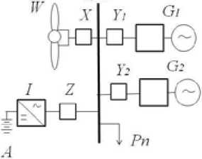
Fig. 1. Autonomous wind-diesel installation: W – wind turbine generator; G1 – working diesel generator; G2 – reserve diesel generator; I – inverter; A – storage battery; X, Z, Y1, Y2 – circuit breaker; Pn – load based reliability approach, due to its inherent capability in simulating the actual process and random behavior of the system, can eliminate uncertainty in reliability modeling.
In the autonomous power systems with RES a small number of basic elements is usually used. Therefore for representation of dynamic operators it is possible to apply Markov models.
As an example of the DFT method application for the reliability analysis of autonomous power system, we will consider the scheme of wind-diesel installation (WDI) (Fig. 1), functioning in the northern regions of Krasnoyarsk region taking into account the wind characteristics [3].
WDI includes basic components: the 225 kW wind power unit, the DG system (two diesel generators, 125 kW each) and storage battery with accumulated energy of 100 kW·h.
The wind-diesel complex includes: two diesel generators G1 and G2, the working one and the reserve one. If the working DG G 1 has a fault, then the reserve DG G 2 is automatically started, and the power supply is recovered. It is often supposed that the reserve unit is ready to work every time there is a need of it. For the model to be true to life, we will make an assumption that the reserve unit can sometimes be not ready for work. So, the fault of DG G2 can happen in attempt of turning it on because of the fault of DG G 1 , and also during inaction of G 2 . Transition of the reserve generator to the – 417 –
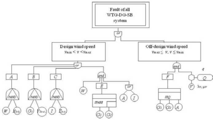
Fig. 2. Dynamic fault tree for reliability analysis of autonomous wind-diesel installation fault condition will have the fault density equal αλ, where α = 0,1. After repair of DG G1, it is placed in operation. Reservation of DG increases reliability of the autonomous power system.
Use of storage battery as a part of the power complex is necessary for smoothing of possible fluctuations of WTG power connected with variable character of wind speed.
Let’s consider fault events of WDI elements, represented in the Fig. 1. The DFT final event is the “Fault of all WTG-DG-SB system”. The corresponding DFT is given in the Fig. 2.
In the reliability analysis of the generation systems, containing WTG, it is necessary to consider wind conditions influencing their functioning. Creation of DFT for WDI considers the design wind speed ν min < ν < ν max at which WTG generates power from zero to rated, and the off-design wind speed ν max ≤ ν; ν ≤ ν min at which WTG does not generate electric power.
When modeling of the design wind speed in DFT the dynamic operators PAND and SPARE are used. The dynamic operator PAND (events at the exit А , В , С) models faults of switches in operation at damage of the corresponding accessions which will lead to the blackout of 0,4 kV collecting bar.
The operator SPARE (event at the exit E ) is applied to modeling of DG system fault. So in case of damage of WTG the working DG can fault, and the attempt to start the reserve DG will not be successful.
Influence of the off-design wind speed on the wind turbine functioning in DFT (Fig. 2) is shown by means of a logical sign “prohibition” (hexagon). Application in DFT of the logical sign “prohibition” allows considering event which happens with some certain probability [5]. In the Fig. 2 the entrance event V, placed under the sign “prohibition”, is the simple WTG because of wind conditions (lack of wind, a hurricane, etc.). The conditional event Q, located sideways from the logical sign, is a restrictive condition which represents a probabilistic weight factor. The restrictive condition is characterized by the value of conditional probability of the off-design wind speed q. The value of the off-design wind speed probability is defined with the help of histogram of wind speed distribution in WDI location. The histogram of wind speed distribution characterizes repeatability of wind speeds for the studied period [3]. It shows how long the wind had a certain speed during the considered period.
Also when modeling of the off-design wind speed in DFT, the dynamic operator SEQ (event at the exit F ) is used, which models faults of other system power sources (DG, SB) in the well-defined ordering. There can be no other sequence of faults of these components.
Thus, in DFT of the WTG-DG-SB system three dynamic operators (PAND , SEQ , SPARE) are used, the representation of which can be executed by means of Markov models [8]. It is necessary to construct a Markov state diagram for each dynamic operator.
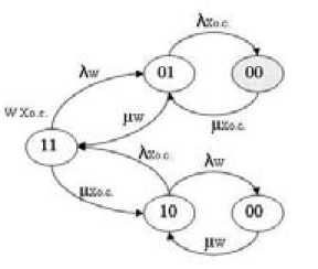
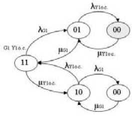
Figures 3-5 show the state space diagrams for the DFT dynamic operators described above. Failure and recovery densities are used as the parameters of these models. The shaded states in the diagrams show the system failure. In each state the figures 1 or 0 indicate the work or the fault of the system elements respectively.
On the basis of the constructed diagrams it is possible to make the system of differential equations, the solution of which allows receiving necessary indicators of reliability: probabilities of k conditions of P k (t) installation and K G availability factor. In our case from the received system of differential equations for each state space diagram it is necessary to define K G availability factor for its further use in the DFT analysis.
For calculation of reliability assessment at the initial stage, with rather short time interval, it is necessary to use a non-stationary availability factor. However in most cases it is enough to define a
a)
b)
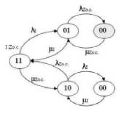
c)
Fig. 3. Markov models for dynamic operators a) PAND(A) ; b) PANDm ; c) PAND(CC : 1 - down state of systems element, 0 – up state; λ – failure rate; µ – repair rate
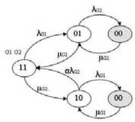
Fig. 4. Markov model for dynamic operator SPARE® : aX - failure rate for reserve diesel
01 02 A
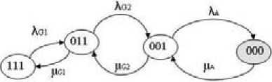
Fig. 5. Markov model for dynamic operator SEQF
stationary availability factor – probability that the recovered object will be operable in the randomly chosen timepoint during a steady-state process ( t →∞).
For each condition k it is possible to write down the following differential equation pk (t ) = - pk (t) £ Xki+^ Aikpi( t), (1)
1 e e ( k ) i e E ( k )
where i e A means that summing is conducted under all such states i which belong to a set A ; E(k) - is a set of states from which the direct transition to some state k is possible; e(k) - a set of states to which the direct transition from this state k is possible; p(t) - probability of the system stay in i state in t timepoint; Xlk — intensity of transition from the state i to the state k .
If the state graph contains n different states, then n different differential equations can be made as a result. For definition of the availability factor it is necessary to write down n equations and one additional equation of the form
n
S Pi = 1.
i = 1
According to (1) and (2) we will receive the system of differential equations for definition of the availability factor of the dynamic operator PAND (A)
P ‘ i ( t ) = U w + ^ x ос ) P ii ( t ) + M w P oi ( t ) + M x ОС . P io ( t);
P ‘ 1 ( t ) = ^ W p 11 ( t ) - ( A X о. с. + P W ) p ( >1 ( t ) + M X о . p °) ( t );
p 0 0 ( t ) = A X ос Р 01 ( t ) + A W p 10 ( t ) - ( p X о.с. + M- W ) P 00 ( t );
P 11 ( t ) + P 01 ( t ) + P 10 ( t ) + P 00 ( t ) = 1 •
To solve the differential equations system and to find the required reliability indicator, a computer program in the Mathcad15 environment was used.
As a result of solution of the equations system, we receive values of states probabilities for the dynamic operator PAND(A) and the stationary availability factor using a formula
PAND ( A )
K G = / . p i .
i = 1
Availability factor for this dynamic operator is К GA (А ) = 0,99.
In the same way let’s find the availability factor for other DFT dynamic operators: К GA AD ( B ) = 0,99;
К PAND (C) G
= 0,99; K SPARE(E) = 0,99 ; К SEQ(F ) = 0,98 .
References Reliability evaluation method of the wind-diesel installation with application of dynamic fault tree
- Твайделл Дж., Уэйр А. Возобновляемые источники энергии: пер. с англ. М.: Энергоатомиздат, 1990. 392 с
- Бобров А.В., Тремясов В.А. Ветродизельные комплексы в децентрализованном электроснабжении. Красноярск: СФУ, 2012. 216 с
- Старков А.Н., Ландберг Л., Безруких П.П., Борисенко М.М. Атлас ветров России. М.: Можайск-Терра, 2000. 560 с
- Эндрени Дж. Моделирование при расчетах надежности в электроэнергетических системах: пер. с англ. М.: Энергоатомиздат, 1983. 336 с
- Гук Ю.Б., Синенко М.М., Тремясов В.А. Расчет надежности схем электроснабжения. Л.: Энергоатомиздат, Ленингр. отд-ние, 1990. 208 с
- Хенли Э.Дж., Кумамото Х. Надежность технических систем и оценка риска. М.: Машиностроение, 1984. 528 с
- Кривенко Т.В. Математическая модель надежности автономной ветродизельной системы на основе метода дерева отказов, Материалы VI Международной молодежной научной конференции «Молодежь и XXI век -2016». Курск: Юго-Зап. гос. ун-т, ЗАО «Университетская книга», 2016, 4, 263-266
- Faulin J., Juan A., Martorell S., and Ramirez-Marquz J.E. (eds) Simulation methods for reliability and availability of complex systems. London, Springer, 2010, 315 p
- Dugan J.B., Sullivan K.J., Coppit D. Developing a low cost high-quality software tool for dynamic fault-tree analysis, IEEE Trans. Reliab., 2000, 49, 49-59
- Huang C.Y., Chang Y.R. An improved decomposition scheme for assessing the reliability of embedded systems by using dynamic fault trees, Reliability Eng. Syst. Saf., 2007, 92(10), 1403-1412
- Amari S., Dill G., Howald E. A new approach to solve dynamic fault trees. In: Annual IEEE reliability and maintainability symposium. Institute of Electrical and Electronics Engineers, New York, 2003, 374-379
- Bobbio A., Portinale L., Minichino M., Ciancamerla E. Improving the analysis of dependable systems by mapping fault trees into Bayesian networks, Reliab. Eng. Syst. Saf. 2001, 71, 249-260
- Karanki D.R., Vinod G., Rao V.V.S.S., Kushwaha H.S., Verma A.K., Ajit S. Dynamic fault tree analysis using Monte Carlo simulation in probabilistic safety assessment, Reliab. Eng. Syst. Saf., 2009, 94, 872-883
- Гук Ю.Б. Анализ надежности электроэнергетических установок. Л.: Энергоатомиздат, 1988. 224 с
- Access: http://www.sienergy.co.uk/WT/downloads/Reliability-andCondition-Monitoring-of-Wind-Turbines.pdf. -Загл. с экрана
