Remote Sensing Image Resolution Enlargement Algorithm Based on Wavelet Transformation

Author: Samiul Azam, Fatema Tuz Zohra, Md Monirul Islam
Journal: International Journal of Image, Graphics and Signal Processing(IJIGSP) @ijigsp
Article in issue: 6 vol.6, 2014.
Free access
In this paper, we present a new image resolution enhancement algorithm based on cycle spinning and stationary wavelet subband padding. The proposed technique or algorithm uses stationary wavelet transformation (SWT) to decompose the low resolution (LR) image into frequency subbands. All these frequency subbands are interpolated using either bicubic or lanczos interpolation, and these interpolated subbands are put into inverse SWT process for generating intermediate high resolution (HR) image. Finally, cycle spinning (CS) is applied on this intermediate high resolution image for reducing blocking artifacts, followed by, traditional Laplacian sharpening filter is used to make the generated high resolution image sharper. This new technique has been tested on several satellite images. Experimental result shows that the proposed technique outperforms the conventional and the state-of-the-art techniques in terms of peak signal to noise ratio, root mean square error, entropy, as well as, visual perspective.
Image resolution, stationary wavelet transformation, cycle spinning, wavelet zero padding
Short address: https://sciup.org/15013301
IDR: 15013301
Text of the scientific article Remote Sensing Image Resolution Enlargement Algorithm Based on Wavelet Transformation
Published Online May 2014 in MECS DOI: 10.5815/ijigsp.2014.06.03
Resolution enhancement of a digital image means increasing the number of pixel-data in a digital image. Intensity values of all these increased pixels should be estimated based on the existing pixel values. Quality of the enhanced image depends on applied estimation method. Basically, interpolation is the process of using known data to estimate values at unknown locations. Four conventional interpolation techniques are used extensively in the field of resolution enhancement, namely, nearest-neighbor, bilinear, bicubic and lanczos. The nearest-neighbor interpolation [1] assigns to each new location the intensity of its nearest neighbor in the original image. This method is simple to implement but produce undesirable artifacts, such as, distortion of straight edges. A more appropriate method is the bilinear interpolation [1], where four nearest neighbors are used to estimate the intensity value of a given location. This method gives slightly better performance than the nearest-neighbor but increases computational cost. In the bicubic interpolation [1], sixteen nearest neighbors are used to estimate the intensity value of a given location.
This method preserves fine details than its bilinear counterpart. The lanczos interpolation [2] has high capability to detect linear features, such as, edge and also produce less aliasing and ringing effect than the nearestneighbor, bilinear and bicubic interpolation. But most of the time its behavior is similar to bicubic interpolation.
Wavelets are being used in many fields of research, as well as, research related to image interpolation and resolution enhancement. So far, many research works, state-of-the-art techniques and conventional methods have been found regarding resolution enhancement and wavelet. One of the known state-of-the-art technique is the regularity preserving image interpolation [3], where a new wavelet high frequency subband is created using extrapolating the local wavelet coefficient decay. This new wavelet subband is used together with the original image to create a high resolution image with a factor of two. Another interpolation based technique for resolution enhancement is the edge-directed interpolation [4], where the covariance-based adaptive interpolation is applied only on the edge pixels and the conventional bilinear interpolation is used for remaining non-edge pixels. This hybrid technique improves the computational cost, as well as, the sharpness of edges. In wavelet and hidden Markov model (HMM) based resolution enhancement techniques [5]-[6], HMM is used to interpolate or estimate high frequency subbands from the low frequency subbands. These estimated high frequency subbands are used in the inverse wavelet transformation to produce the high resolution image. Another state-of-the-art technique is found in [7], which have shown best result over all the above state-of-the-art-techniques, as well as, the conventional methods. In this paper, we have proposed a different approach for image resolution enhancement, where stationary wavelet transformation, cycle spinning and the Laplacian sharpening filter has been used. Experimental result has confirmed the superiority of this technique over the conventional and the state-of-the-art techniques.
This paper is organized as follows: section II describes basic idea about the wavelet decomposition of an image, the conventional wavelet techniques and the summary of technique [7] and [8]. Section III explains the proposed resolution enhancement and the algorithm of this approach. Experimental result is presented in section IV, and lastly the conclusion of this paper is outlined in section V.
-
II. Wavelet and resolution enlargement
Wavelet transformation is an excellent tool for processing and analyzing digital images. Many research works related to image processing, such as, image classification [9], image contrast enhancement [10], image compression [11]-[13] and image denoising [14][15] are found in wavelet domain. More likely, researcher use 2D wavelet decomposition and reconstruction for their image analysis and image frequency division. 2D wavelet decomposition of an image is performed by applying the 1D discrete wavelet transform (DWT) along the rows of the image first, and then again 1D DWT along the column of the image. This 2D wavelet decomposition will make four decomposed subband images referred to low-low (LL), low-high (LH), high-low (HL), and high-high (HH). All those four subbands cover the full frequency band of the original image. In Fig. 1, a filter bank is shown, that should function on the image in order to generate frequency images of different subbands.
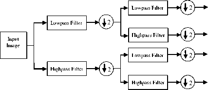
Fig 1: Filter bank of 2D wavelet decomposition
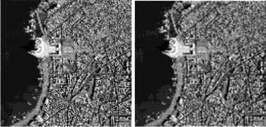
Fig. 2 shows a remote sensing image (satellite image) decomposed into four subbands using the 2D-DWT. The LL subband is considered as approximation of the original image and the other three subbands HL, LH, HH are considered as horizontal, vertical and diagonal details of the original image, respectively. Inverse 2D-DWT can be applied on those four subbands to get back the original image without loss of information [1].
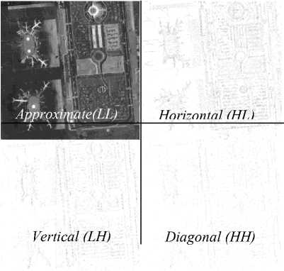
Fig 2: Discrete wavelet decomposition of a satellite image.
LL HL LH HH
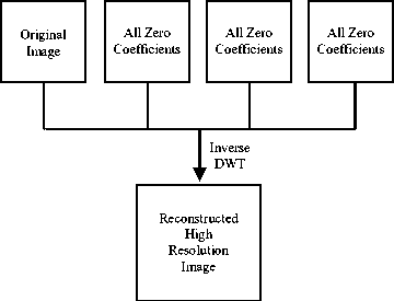
Fig 3: Block diagram of WZP resolution enhancement.
One of the simplest wavelet domain resolution enhancement techniques is wavelet zero padding (WZP) where simply the inverse 2D-DWT is used (see Fig. 3). Before the inverse process, LL subband is considered as the original image and the LH, HL, HH subbands are filled with zero frequency values. After the inverse 2D-DWT, we get the resolution enhanced image with a factor of two. A similar conventional image resolution technique can be possible using the stationary wavelet transformation and subbands zero padding (SWT-ZP). Stationary wavelet transformation is similar to DWT except that, there is no down sampling of signals. In SWT-ZP technique all high frequency subbands’ coefficients are considered as zero before the inverse process. The LL subband is replaced with interpolated input image with a factor of α (alpha). Finally, an inverse SWT will produce the high resolution image (see Fig. 4). Although WZP and SWT-ZP is very simple to implement but it gives less performance than the bicubic, if the original image contains much edge and texture pixels.
In this paper, our proposed enhancement technique has
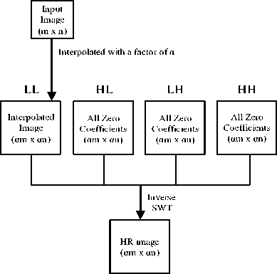
Fig 4: Block diagram of SWT-ZP resolution enhancement.
been compared with all the conventional techniques, and two well performed state-of-the-art techniques that are found in [7] and [8]. In [7], an initial approximate HR image is generated using WZP. This approximate HR image is passes through CS process where a number of high resolution images are generated using spatial shifting and wavelet zero padding. All these images are then reversely shifted and averaged to give the final HR image. In [8] (known as DASR technique), the original image and all the wavelet high frequency subbands are interpolated using the bicubic interpolation and finally put them all into the inverse DWT to get the HR image. This state-of-the-art technique gives better result than all the above state-of-the-art techniques, as well as, the conventional approaches.
-
III. Proposed tecghnique and its algorithm
In this paper, we take satellite images (remote sensing images) into our special consideration for resolution enhancement. Most of the satellite image contains much edge pixels than regular images. These features of an image constitute to high frequency components of an image. A conventional image resolution enhancement technique does not preserve high frequency features of an image. But for remote sensing images (such as satellite image) presence of high frequency data (such as edges) is more desirable. That’s why preserving high frequency components are needed for edge and texture rich images when they are interpolated.
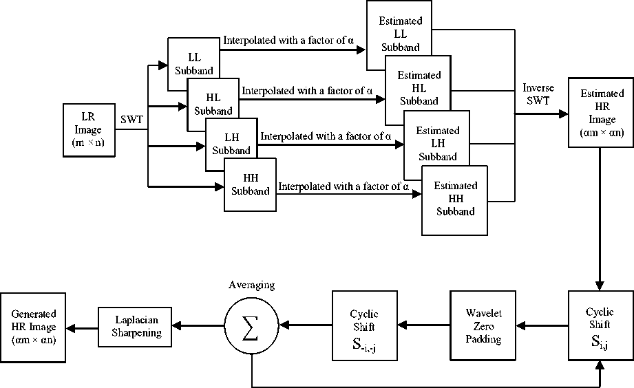
In our proposed technique, SWT is used to preserve high frequency components and cycle spinning is used to eliminate blocking artifacts. See the block diagram of our proposed technique at Fig. 5. SWT is applied to initial (m x n) size low resolution (LR) image and generate four frequency subbands, namely, LL, HL, LH and HH. The HL, LH and HH subbands contain high frequency components of an image. All these four subbands are interpolated with a factor of α. We can use either bicubic or lanczos interpolation at this intermediate interpolation step. These high resolution SWT subbands are put into inverse SWT to produce HR image of resolution (αm x αn). Next, this intermediate (or estimated) HR image is going through CS process. Inside CS process N=(2k+1)(2k+1) number of cyclic shifted version of intermediate HR image is generated. In this paper, the shift operation is denoted as Si,j where –k ≤ i,j ≤ k and a good choice of value of k is 4. All these images are then wavelet transformed and padded with zeros except LL subband. Inverse wavelet transformation and reverse cyclic shift is also applied to these images. Finally they are averaged at end of CS process and sharpened using traditional laplacian filter at the end.
In this paper, we have given a simple algorithm of this new technique for implementation purpose. We already stated that, either bicubic or lanczos interpolation can be applied at the intermediate step of SWT subbands interpolation. We use both bicubic and lanczos separately, but take one output that makes maximum PSNR value. Algorithm of this new technique has been given in the form of two functions: SWT_CS_ENHANCEMENT and PROPOSED TECH.
Repeat it for all possible pairs of {i , j} where -k ≤ i ≤ k and -k ≤ j ≤ k.
Fig 5: Proposed SWT and CS based resolution enhancement technique.
SWT_CS_ENHANCEMENT(X,α):
A = PROPOSED_TECH(‘Lanczos’,X,α)
B = PROPOSED_TECH(‘Bicubic’,X,α)
OUT = Image A or B based on Maximum PSNR
Return OUT
PROPOSED_TECH(inter_type, X, α):
[LL, HL, LH, HH] = SWT of image X
[LL’, HL’, LH’, HH’] = Interpolation of [LL, HL, LH, HH] with factor α using inter_type
HR’ = Inverse SWT with [LL’, HL’, LH’, HH’]
SUM = Zero image
For i = -k to k
For j = -k to k
Y = HR’ * S i,j
WZP of Y
Y’ = Y * S -i,-j
SUM = SUM + Y’
End For
End For
N = (2k+1)*(2k+1)
Y’’ = SUM / N
Y’’’ = Sharper version of image Y’’ using Laplacian filter
Return Y’’’
In the above pseudo-code X is the input image, HR’ is the intermediate high resolution image, OUT is the resulted HR image and α is the enlargement factor. As we can see in the algorithm, proposed technique is applied two times for same input image with different interpolation. Both bicubic and lanczos interpolation have less blocking artifacts and modest level of blurring effect rather than nearest-neighbor and bilinear.
-
IV. Experimental result
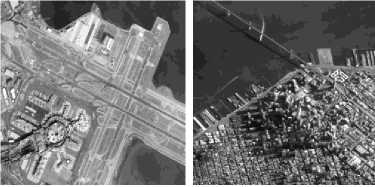
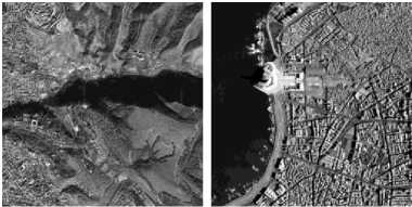
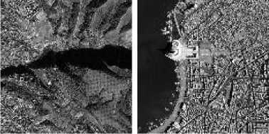
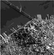
The proposed method has been tested on several satellite images that are collected from Satellite Imaging Corporation [16]. In this paper, we have selected four particular satellite images for describing experimental result. Initially, four LR satellite images of resolution 256 x 256 are generated from down sampling of original HR satellite images (see Fig. 6) of resolution 512 x 512. Similarly, we have also obtained four LR satellite images of resolution 128 x 128 by applying two cascaded down sampling (see Fig. 7). All images used in this experiment are quantized to 8-bit grayscale images. For implementation and simulation, we have chosen MATLAB programming and toolboxes for image processing and wavelet transformation. In order to show the superiority of the proposed method over the conventional and the state-of-the-art techniques, we have included both visual and quantitative comparisons. We have considered following resolution enhancement techniques for comparisons:
-
- - Nearest-neighbor interpolation
-
- - Bilinear interpolation
-
- - Bicubic interpolation
(a) Image 1
(b) Image 2
(c) Image 3
(d) Image 4
Fig 6: High Resolution (512 x 512) satellite images.
(a) Image 1
(b) Image 2
(c) Image 3 (d) Image 4
Fig 7: Low resolution (128 x 128) satellite images obtained from down sampling of images in Figure.6.
-
- - Lanczos interpolation
-
- - WZP using Haar wavelet
-
- - SWT-ZP using Haar wavelet and interpolation
-
- - WZP and CS [7]
-
- - DASR [8]
Experimental result shows the outperformance of the proposed technique over the above existing techniques in both visual and quantitative way.
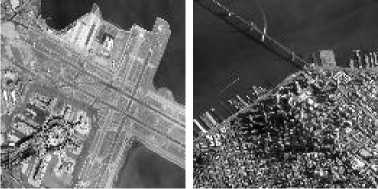
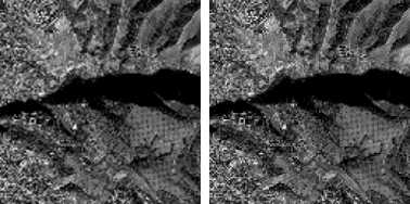
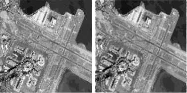
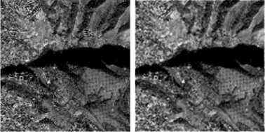
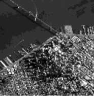
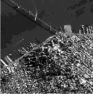
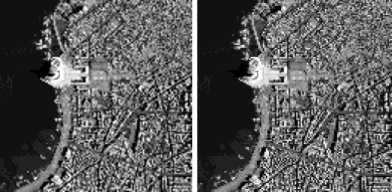
For visual comparison, we have generated high resolution satellite images with a factor of 4 from low resolution (128 x 128) images (shown in Fig.7) using above existing techniques, as well as, the proposed technique. In this paper, we have considered images generated using bicubic interpolation, WZP with Haar wavelet, WZP and Haar wavelet with cycle spinning [7] and the proposed approach. See Fig. 8 for satellite image 1 where the proposed technique shows less blocking artifacts and moderate level of blur effect. See also Fig. 9, Fig. 10 and Fig. 11 for visual comparisons of other three satellite images.

(a) Bicubic (b) WZP(Haar)
(a) Bicubic (b) WZP(Haar)
(c) WZP(Haar) and CS
(d) Proposed
Fig 8: High resolution (512 x 512) satellite images generated using (a) Bicubic, (b) WZP (Haar), (c) WZP (Haar) with CS and (d) the proposed algorithm for image 1.
(c) WZP(Haar) and CS
(d) Proposed
(a) Bicubic
(b) WZP(Haar)
Fig 10: High resolution (512 x 512) satellite images generated using (a) Bicubic, (b) WZP (Haar), (c) WZP (Haar) with CS and (d) the proposed algorithm for image 3.
(a) Bicubic (b) WZP(Haar)

(c) WZP(Haar) and CS
(d) Proposed
(c) WZP(Haar) and CS
(d) Proposed
Fig 11: High resolution (512 x 512) satellite images generated using (a) Bicubic, (b) WZP (Haar), (c) WZP (Haar) with CS and (d) the proposed algorithm for image 4.
Fig 9: High resolution (512 x 512) satellite images generated using (a) Bicubic, (b) WZP (Haar), (c) WZP (Haar) with CS and (d) the proposed algorithm for image 2.
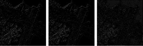
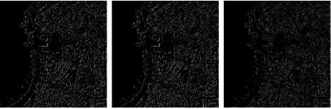
Another way of visual comparison can be done by observing error image. Subtracting the generated HR image from the original HR image may produce the error image. Error image with higher number of black pixels means less difference between two images. In image resolution, much blackish error image is more desirable. We have generated error images for evaluating the performance of bicubic interpolation, WZP (Haar) with CS [7] and the proposed technique. See Fig. 12, Fig. 13, Fig. 14 and Fig. 15 for visualizing error images of above four satellite images. Proposed method shows less error than others.
Our visual result shows that the proposed method gives slightly better images over all the competing techniques. But dominance of our proposed technique over the competing techniques has been confirmed in the quantitative comparisons where consistent improvement of quantitative measures found. We consider peak signal to noise ratio (PSNR) and root mean square error (RMSE) between original HR and generated HR image as quantitative measure [1]. Also entropy (amount of information) of generated image in bits/pixel is reflected as quantitative measure.
-}
RMSE = sqrt{
Z i.j(jorg(i,D-IgAU)
M x N
RMSE can be obtained by using the following equation (Eqn. 1) where Iorg is the original image, Ige is the generated image and (M, N) is the dimension of the image. For our experiment (M,N) = (512, 512) . PSNR (Eqn. 2)
can be defined as following where L is the maximum fluctuation in the input image. As we have used 8-bit grayscale image, so the value of L = 255 . The entropy (Eqn. 3) of an image can be denoted as below where p r (r k ) is the probability of intensity value r k .
I?PSNR = 10 log^-^) (2)
L-l e = - ^ P(^)i io g 2 рЛ1)) (3)
k=0
(a) Bicubic (b) WZP(Haar) with CS (c) Proposed
Fig 12: Error images for evaluating (a) Bicubic, (b) WZP (Haar) with CS and (c) the proposed technique for image 1.

(a) Bicubic (b) WZP(Haar) with CS (c) Proposed
Fig 13: Error images for evaluating (a) Bicubic, (b) WZP (Haar) with CS and (c) the proposed technique for image 2.

(a) Bicubic (b) WZP (Haar) with CS (c) Proposed
Fig 14: Error images for evaluating (a) Bicubic, (b) WZP (Haar) with CS and (c) the proposed technique for image 3.
(a) Bicubic (b) WZP(Haar) with CS (c) Proposed
Fig 15: Error images for evaluating (a) Bicubic, (b) WZP (Haar) with CS and (c) the proposed technique for image 4.
In Tables 1 and 2, we have shown the comparison among the conventional, the state-of-the-art [7]-[8] and the proposed techniques in terms of PSNR and RSME respectively. Here, we consider enhancement factor 4 that means image resolution enhancement from (128 x 128) to (512 x 512). In the Tables, quantitative measure of the proposed technique is calculated using bicubic and lanczos interpolation separately. But the proposed algorithm took the best result between them as stated in the last row of every table. All the wavelet transformations in this experiment are performed using Haar mother wavelet for consistency in comparison.
From Table 1 and 2, we have found maximum PSNR value and minimum RSME value for image 1, 2, 3 and 4 on proposed resolution enhancement technique. Even, we can calculate the entropy value of negative error images for each different technique. For our proposed technique, we have found minimum entropy value which confirms that our proposed technique has fewer errors than others. See Table 3 for entropy values of negative error images. Table 4 reflects the capability of our proposed technique with factor 2 in terms of PSNR. From these visual and quantitative experiments, we have proved our proposed technique as better technique than all the aforementioned competing conventional and the state-of-the-art [7]-[8] techniques.
Table I. PSNR results of resolution enhancement of factor 4 for the proposed technique compared with T he conventional and the state - of - the - art techniques .
|
Methods or techniques |
PSNR (dB) |
|||
|
Image 1 |
Image 2 |
Image 3 |
Image 4 |
|
|
Nearest |
18.4497 |
15.9100 |
15.6680 |
13.0509 |
|
Bilinear |
19.7956 |
17.5609 |
17.3195 |
14.6991 |
|
Bicubic |
19.6507 |
17.0784 |
16.5925 |
14.1562 |
|
Lanczos |
19.6363 |
17.0647 |
16.5776 |
14.1404 |
|
WZP(Haar) |
18.4497 |
15.9100 |
15.6680 |
13.0509 |
|
SWT-ZP(Nearest) |
18.4070 |
16.0020 |
15.8330 |
13.0102 |
|
SWT-ZP(Bilinear) |
18.9762 |
17.0246 |
16.9586 |
14.1404 |
|
SWT-ZP(Bicubic) |
18.9442 |
16.5494 |
16.2725 |
13.5782 |
|
SWT-ZP(Lanczos) |
18.9322 |
16.5369 |
16.2590 |
13.5641 |
|
WZP and CS [7] |
19.4161 |
16.8739 |
16.4686 |
13.9534 |
|
DASR [8] |
18.9728 |
16.1245 |
17.7189 |
14.9326 |
|
Proposed(Bicubic) |
20.5463 |
18.6125 |
18.6359 |
16.0245 |
|
Proposed(Lanczos) |
20.5229 |
18.6318 |
18.6635 |
16.0276 |
|
Proposed |
20.5463 |
18.6318 |
18.6635 |
16.0276 |
Table II. RMSE results of resolution enhancement of factor 4 for the proposed technique compared with the conventional and the state-of-the-art techniques.
|
Methods or techniques |
RMSE |
|||
|
Image 1 |
Image 2 |
Image 3 |
Image 4 |
|
|
Nearest |
30.4827 |
40.8356 |
41.9895 |
56.7535 |
|
Bilinear |
26.1071 |
33.7671 |
34.7189 |
46.9446 |
|
Bicubic |
26.5463 |
35.6961 |
37.7499 |
49.9725 |
|
Lanczos |
26.5904 |
35.7526 |
37.8145 |
50.0634 |
|
WZP(Haar) |
30.4827 |
40.8356 |
41.9895 |
56.7535 |
|
SWT-ZP(Nearest) |
30.6330 |
40.4056 |
41.1991 |
57.0206 |
|
SWT-ZP(Bilinear) |
28.6900 |
35.9177 |
36.1918 |
50.0634 |
|
SWT-ZP(Bicubic) |
28.7958 |
37.9378 |
39.1666 |
53.4107 |
|
SWT-ZP(Lanczos) |
28.8358 |
37.9923 |
39.2273 |
53.4978 |
|
WZP and CS [7] |
27.2730 |
36.5465 |
38.2920 |
51.1527 |
|
DASR [8] |
26.2048 |
33.6723 |
34.5221 |
46.8590 |
|
Proposed(Bicubic) |
23.9455 |
29.9170 |
29.8362 |
40.3011 |
|
Proposed(Lanczos) |
24.0100 |
29.8503 |
29.7415 |
40.2865 |
|
Proposed |
23.9455 |
29.8503 |
29.7415 |
40.2865 |
V. Conclusion
In this paper, a new image resolution enhancement technique has been presented. Through experimental results this technique proves its superiority over the conventional and the state-of-the-art techniques. We have presented both visual and quantitative comparison in terms of PSNR, RMSE and entropy. In this technique, stationary wavelet subband padding is used to preserve high frequency features of an image. To reduce blocking artifacts and blurring effects cycle spinning and Laplacian sharpening are applied on intermediate high resolution image. We also proposed an algorithm of our technique for practical implementation purpose. In this algorithm, proposed technique is applied on LR image for two times and takes the best image that has maximum PSNR value. We use Haar mother wavelet in all wavelet based techniques for consistency in comparisons. Mixing of different wavelets is avoided during experimental comparison. Analysis and behavior of our proposed technique for different wavelets are kept for future work.
Table III. Entropy results of resolution enhancement of factor 4 for the proposed technique compared with the conventional and the state-of-the-art techniques.
|
Methods or techniques |
Entropy of negative error image |
|||
|
Image 1 |
Image 2 |
Image 3 |
Image 4 |
|
|
Nearest |
5.6177 |
5.6439 |
6.3330 |
6.2860 |
|
Bilinear |
5.5372 |
5.5358 |
6.0990 |
6.2629 |
|
Bicubic |
5.5073 |
5.6203 |
6.2129 |
6.3322 |
|
Lanczos |
5.5119 |
5.6278 |
6.2159 |
6.3365 |
|
WZP(Haar) |
5.6177 |
5.6439 |
6.3330 |
6.2860 |
|
SWT-ZP(Nearest) |
5.6887 |
5.7630 |
6.3320 |
6.4970 |
|
SWT-ZP(Bilinear) |
5.6954 |
5.6696 |
6.1672 |
6.3771 |
|
SWT-ZP(Bicubic) |
5.6391 |
5.7424 |
6.2719 |
6.4517 |
|
SWT-ZP(Lanczos) |
5.6423 |
5.7461 |
6.2741 |
6.4543 |
|
WZP and CS [7] |
5.5114 |
5.5874 |
6.2192 |
6.3278 |
|
DASR [8] |
5.5362 |
5.5853 |
6.0261 |
6.2763 |
|
Proposed(Bicubic) |
5.4503 |
5.3661 |
5.8823 |
6.1198 |
|
Proposed(Lanczos) |
5.4514 |
5.3629 |
5.8771 |
6.1236 |
|
Proposed |
5.4503 |
5.3629 |
5.8771 |
6.1198 |
Table IV. PSNR results of resolution enhancement of factor 2 for the proposed technique compared with the conventional and the state-of-the-art techniques.
|
Methods or techniques |
PSNR(dB) |
|||
|
Image 1 |
Image 2 |
Image 3 |
Image 4 |
|
|
Nearest |
22.2687 |
19.9218 |
18.3432 |
17.2279 |
|
Bilinear |
23.5075 |
21.4773 |
20.2522 |
18.9289 |
|
Bicubic |
23.6334 |
21.3934 |
19.4173 |
18.7055 |
|
Lanczos |
23.6108 |
21.3782 |
19.3951 |
18.6886 |
|
WZP(Haar) |
22.2687 |
19.9218 |
18.3432 |
17.2279 |
|
SWT-ZP(Nearest) |
21.3606 |
19.2078 |
17.9714 |
16.0779 |
|
SWT-ZP(Bilinear) |
21.3863 |
19.4831 |
18.7547 |
16.6515 |
|
SWT-ZP(Bicubic) |
21.5345 |
19.3799 |
18.2727 |
16.2766 |
|
SWT-ZP(Lanczos) |
21.5105 |
19.3604 |
18.2484 |
16.2555 |
|
WZP and CS [7] |
23.4929 |
21.4915 |
20.0515 |
18.8919 |
|
DASR [8] |
23.2921 |
21.7330 |
20.0023 |
19.1029 |
|
Proposed(Bicubic) |
23.7614 |
21.9019 |
20.8064 |
19.8407 |
|
Proposed(Lanczos) |
23.8017 |
21.8800 |
20.7881 |
19.8577 |
|
Proposed |
23.8017 |
21.9019 |
20.8064 |
19.8577 |
References Remote Sensing Image Resolution Enlargement Algorithm Based on Wavelet Transformation
- R. C. Gonzalez and R. E. Woods, Digital image processing: 3rd edition, Englewood Cliffs, NJ: Prentice-Hall, 2008.
- T. Acharya and P. S. Tsai, "Computational foundation of image interpolation algorithms," ACM Ubiquity, 8, 2007, pp. 121-137.
- W. K. Carey, D. B. Chuang and S. S. Hemami, "Regularity preserving image interpolation," IEEE Trans. on Image Proc., Vol. 8, No. 9, Sep. 1999, pp. 1295–1297.
- X. Li and M.T. Orchard, "New edge-directed Interpolation," IEEE Trans. on Image Proc., Vol. 10, No.10, Oct. 2001, pp. 1521-1527.
- W. K. Carey, D. B. Chuang and S. S. Hemami, "Regularity-preserving image interpolation," IEEE Trans. on Image Proc., Vol. 8, No. 9, Sep. 1999, pp. 1295–1297.
- S. Zhao, H. Han and S. Peng, "Wavelet Domain HMT-Based Image Superresolution," IEEE International Conf. on Image Proc., Vol. 2, Sep. 2003, pp. 933-936.
- A. Temizel and T. Vlachos, "Wavelet Domain Image Resolution Enhancement Using Cycle-Spinning", IEE Elec. Letters, vol. 41, no. 3, Feb. 2005, pp-119-121.
- G. Anbarjafari and H. Demirel, "Image super-resolution based on interpolation of wavelet domain high frequency subbands and the spatial domain input image," ETRI journal, Vol. 32, No. 3, Jan 2010, pp. 390-394.
- A. Daamouche and F. Melgani, "Swarm Intelligence Approach to Wavelet Design for Hyperspectral Image Classification," IEEE Geo. and Remote Sensing Letters, Vol. 6, No. 4, Oct. 2009, pp. 825-829.
- H. Demirel, C. Ozcinar, and G. Anbarjafari, "Satellite Image Contrast Enhancement Using Discrete Wavelet Transform and Singular Value Decomposition," IEEE Geo. and Remote Sensing Letters, Vol. 7, No. 2, Apr. 2010, pp. 333-337.
- B. Li, R. Yang and H. Jiang, "Remote-Sensing Image Compression Using Two-Dimensional Oriented Wavelet Transform," IEEE Geo. and Remote Sensing Letters, Vol. 49, No. 1, Jan. 2011, pp. 236-240.
- I.B. Hacene, M. Beladgem and A. Bessaid, "Lossy Compression Color Medical Image Using CDF Wavelet Lifting Scheme," IJIGSP, MECS publisher, Vol. 5, No. 12, Sep. 2013, pp. 53-60.
- M. M. Fouad and R. M. Dansereau, "Lossless Image Compression Using A Simplified MED Algorithm with Integer Wavelet Transform," IJIGSP, MECS publisher, Vol. 6, No. 01, Nov. 2013, pp. 18-23.
- E. J. Balster, Y. F. Zheng and R. L. Ewing, "Feature-Based Wavelet Shrinkage Algorithm for Image Denoising," IEEE Tran. on Image Proc., Vol. 14, No. 12, Dec. 2005, pp. 1024-1039.
- S. D. Ruikar and D. D. Roye, "Image Denoising Using Tri Nonlinear and Nearest Neighbor Interpolation with Wavelet Transform," IJITCS, MECS publisher, Vol. 4, No. 09, Aug. 2012, pp. 36-44.
- Internet: http:\\www.satimagingcorp.com\gallery.html, [Oct. 07, 2013].
