Research of acoustically improved Helmholtz resonator

Author: Li Jun, Shan Jingwei, Guo Zhengyang, Levtsev Aleksei
Journal: Бюллетень науки и практики @bulletennauki
Section: Технические науки
Article in issue: 1 т.7, 2021.
Free access
The three-dimensional acoustic finite element method is used to predict the transmission loss of the Helmholtz resonance muffler. The results are in good agreement with the experimental results, indicating the applicability and accuracy of the numerical method used in this paper. On the one hand, in order to reduce the resonance frequency without changing the shape of the resonator, the connecting tube is extended to the inside of the resonator, and the influence of the extension length and the cross section shape of the extension tube on the acoustic characteristics of the resonator is discussed in detail. On the other hand, in order to broaden the muffled frequency band of the traditional Helmholtz resonators, the resonators are combined in series and parallel, and the influence of the combined structure on the acoustic characteristics is discussed in detail.
Acoustics, helmholtz, muffler, finite element
Short address: https://sciup.org/14117933
IDR: 14117933 | UDC: 534.833.534 | DOI: 10.33619/2414-2948/62/27
Text of the scientific article Research of acoustically improved Helmholtz resonator
Бюллетень науки и практики / Bulletin of Science and Practice
UDC 534.833.534
The traditional Helmholtz resonator is usually composed of a closed cavity and a connecting pipe in series. The cavity passes through the connecting pipe and communicates with the main pipe, as shown in Figure 1 [1] . Because of its simple structure and high low frequency noise attenuation, it is widely used to suppress the sound propagation in ship ventilation and air conditioning pipelines and diesel engine inlet and exhaust pipes. Nevertheless, traditional Helmholtz resonators still have the following disadvantages:
The resonance frequency depends on the geometry size of cavity and connecting pipe. In order to meet the requirement of further reducing the noise elimination frequency in engineering practice, the volume of cavity or the length of connecting pipe must be increased. However, the space layout of ship internal ventilation pipeline system, intake and exhaust system of internal combustion engine is very compact, and the control of equipment dimension is very strict. It is not very feasible to reduce the acoustic attenuation frequency by increasing the size of the resonator.
Strong noise attenuation frequency selectivity, narrow noise attenuation frequency band, only at its resonant frequency, when deviating from the resonant frequency, its noise attenuation tends to be very fast, difficult to adapt to some excitation frequency changes or the actual application of wide noise attenuation frequency band requirements.
Therefore, based on three-dimensional acoustic finite element method, some adaptive improvements were made to Virtual. Lab Acoustics by using simulation analysis software based on the geometric structure of traditional Helmholtz resonators, so as to effectively broaden the application scope of Helmholtz resonators [2].
Acoustic performance of muffler
The acoustic performance indexes of the muffler are transmission loss (TL) and insertion loss (IL), among which transmission loss is only related to the body structure and is not affected by the source characteristics and tail pipe radiation characteristics, which is the most commonly used performance index in muffler research [3]. When the muffler inlet and outlet meet the plane wave conditions, the transmission loss can be expressed as:
TL = 20lg
pi
pt
In the formula, pi and pt are respectively the incident sound pressure at the inlet of the muffler and the transmitted sound pressure at the outlet. Assuming that the sound pressure at the
pv p
inlet is 1 , the particle velocity of vibration is 1 , and the sound pressure at the outlet is 2 , the transfer loss can be expressed as:
TL = 20lg
P 1 + Pc 0 v 1
2 p 2
c
In the formula: is the air density; 0 is the speed of sound. According to Equation (2), when v1 is known or given, the sound pressure field in the muffler can be calculated by using the finite element method, and then the value of sound pressure at its inlet and outlet can be substituted into Equation (2) to obtain the transmission loss of the muffler.
Numerical calculation and analysis
Figure 1. shows a typical Helmholtz resonance muffler. In this study, cavity diameter D = 15.319 cm, length L = 24.4 cm, connecting pipe diameter D = 4.044 cm, length L =8.5 cm, main pipe diameter D = 4.859 cm, sound velocity c =340 m/s.
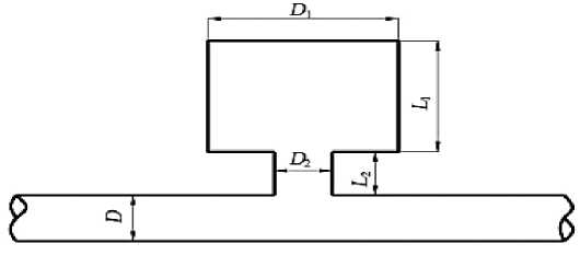
Figure 1. Typical structure of Helmholtz resonator.
Figure 2 shows the finite element discretization grid of the Helmholtz resonator muffler. It can be seen from Figure 3 that the transfer loss predicted by the finite element method is in good agreement with the experimental results in literature [4] within the frequency range we care about, which indicates the accuracy of the finite element method in predicting the muffler's sound attenuation performance. It can be seen from the calculation results that the transmission loss of the Helmholtz resonance muffler appears an obvious resonance peak at about 88 Hz.
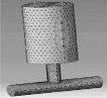
Figure 2. Acoustical finite element model of Helmholtz resonator.
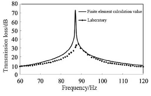
Figure 3. Transmission loss of Helmholtz resonator.
Influence of extension of connecting pipe on noise attenuation characteristics of Helmholtz resonator.
According to the classical lumped parameter theory, the resonance frequency fr of the Helmholtz resonator can be expressed as:
S 2
c 0
Jr 2n\i V ( l 2 + 5 )
In the formula, c is the sound velocity; V is the cavity volume; l is the length of connecting pipe; S 2 is the cross-sectional area of the connecting pipe; <5 is acoustic end correction.
According to formula (3), in order to reduce the resonance frequency, it is necessary to increase the volume of the cavity or the length of the connecting pipe. However, in practical engineering applications such as the internal pipeline of the ship and the internal combustion engine intake and exhaust pipe, the equipment is arranged in a compact manner and the external size of the equipment is strictly controlled. Therefore, it is particularly important to further reduce the common vibration frequency without increasing the cavity volume and the length of the connecting pipe, or to reduce the cavity volume and the length of the connecting pipe while maintaining the resonance frequency [5].
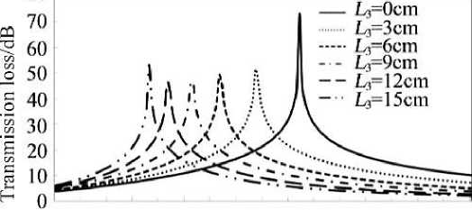
In order to achieve the above noise-suppressing effect, the connecting pipe can be extended into the cavity with the length of L , as shown in Figure 4, while the influence of L on resonance frequency is shown in Figure 5, on the premise of keeping other dimensions unchanged. As can be seen from Figure 5, the extension length L of the connecting tube can effectively reduce the resonance frequency of the Helmholtz resonator. For the structure adopted in this paper, when the extension length L = 15 cm, the resonance frequency can be reduced by about 30 Hz, which is quite considerable in engineering practice. However, as the extension length increases, the resonance frequency decreases gradually. According to the calculation results of transmission loss shown in Figure 6, as the extension length increases gradually, not only the resonance frequency decreases, but also the muffled sound frequency band gradually Narrows.
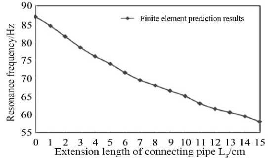
Figure 5. The effect of length of extended connecting tube on the resonance frequency of Helmholtz resonator .
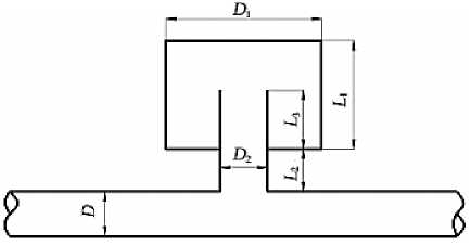
Figure 4. Helmholtz resonator with extended connecting .
40 45 50 55 60 65 70 75 80 8 5 9 0 95100105110115120 Frequency/Hz
Figure 6. The effect of length of extended connecting tube on the transmission loss of Helmholtz resonator.
Figure 7 shows the influence of extension length L3 on resonance frequency when the cavity position is moved along the center line of the connecting pipe with the sum Ln (15.5cm) of length L2 (8.5 cm) and extension length L3 (7 cm) of the connecting pipe remains unchanged. It can be seen from Figure 7 that, when the total length of Ln is kept unchanged, the change of L3 has little effect on resonance frequency.
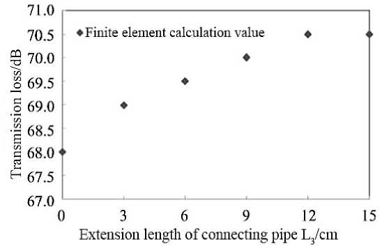
Figure 7. The effect of length of extended connecting tube on the resonance frequency of Helmholtz resonator (fixed total length L = L + L ).
On the basis of Figure 4, Figure 8 shows the structure diagram of the Helmholtz resonator when the cross section of the extension pipe is contracted or expanded, and Figure 9 shows the comparison of the transfer loss of the extension pipe when it is straightened by 5 and expanded by 10 and when it is straightened by the extension pipe under the premise of keeping L 3 = 10 cm. It can be seen from Fig. 9 that the contraction or expansion of the extension tube has an obvious regulating effect on the resonance frequency. When the extension tube is contracted by 5 , the resonant frequency can be further reduced on the premise of the straight extension tube, but the muffler frequency band will be further narrowed. However, when the extension tube is expanded by 10 , the resonant frequency will increase, but the muffler frequency band will also be wider.
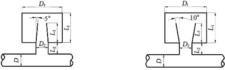
Figure 8. Helmholtz resonator with contraction / expansion extended connecting tube.
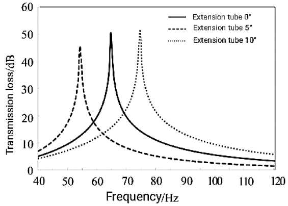
Figure 9. The effect of contraction / expansion on the transmission loss of Helmholtz resonator.
-
2. The Influence of series and parallel combination structure on the Silencing characteristics of Helmholtz resonators
The Figure 3 shows that Helmholtz resonant muffler at resonance frequency of large amount of noise elimination, decrease the attenuation faster when deviating from the resonance frequency, there is silencing narrow frequency band, the frequency selectivity of the faults, and in practical engineering applications often have multiple frequency or incentives frequency changes, and the noise is also relatively wide frequency band, so the above single lumen Helmholtz resonant muffler is often difficult to meet the demand of practical engineering noise reduction. Therefore, in this paper, a series and parallel combination of resonant cavity and connecting pipe is carried out in order to effectively widen the noise attenuation band of the Helmholtz resonator muffler.
Figure 10 is the schematic diagram of parallel structure of Helmholtz resonator, and Figure 11 is the calculation result of corresponding transfer loss. As can be seen from Fig. 11, when a resonator of the same shape is connected in parallel (as shown in Figure 10 (a)), the resonant frequency of the Helmholtz resonator does not change, but its acoustic attenuation frequency band becomes significantly wider. However, when a connecting pipe of the same shape is connected in parallel (as shown in Figure 10(b)), the resonance frequency of the Helmholtz resonator will increase, and the acoustic attenuation frequency band will also widen accordingly. According to Equation (3), it can be seen that this is mainly caused by the increase of the cross-sectional area of the connecting pipe.
Figure 12 is the schematic diagram of series structure of Helmholtz resonator, and Figure 13 is the calculation result of corresponding transfer loss. It can be seen from Figure 13 that, when a resonator of the same shape is connected in series, the original transmission loss resonator peak of the Helmholtz resonator will disappear, and two new resonators will be created on both sides of the original resonator instead. Moreover, when the resonator is connected in series or outside the resonator, there is no significant difference in the acoustic attenuation characteristics of the resonator.
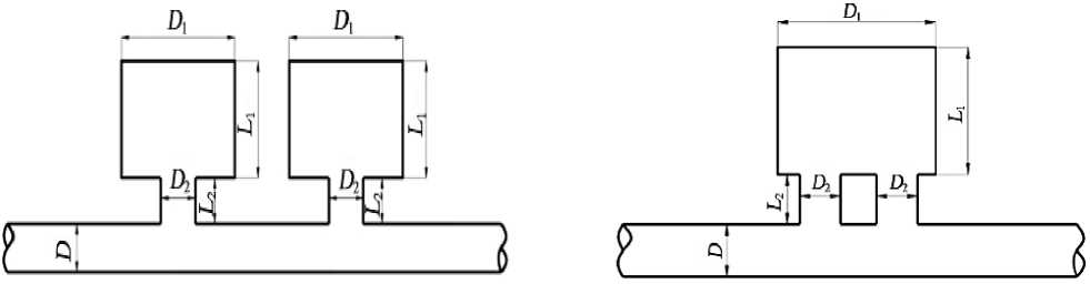
(a) Cavity parallel connection (b) Connecting pipes parallel connection
Figure 10. Helmholtz resonators in parallel.
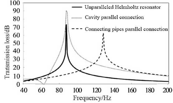
Figure 11. Transmission loss of Helmholtz resonator in parallel.
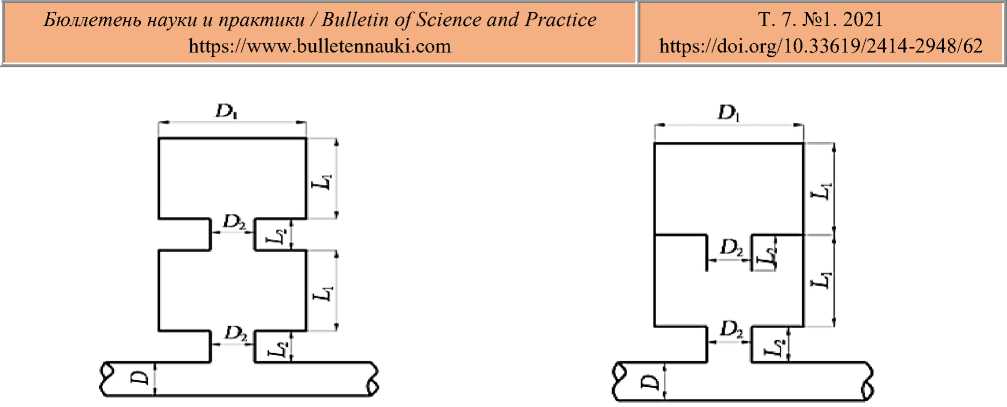
(a) Intracavity series connection
(b) Extraluminal series connection
Figure 12. Helmholtz resonators in series.
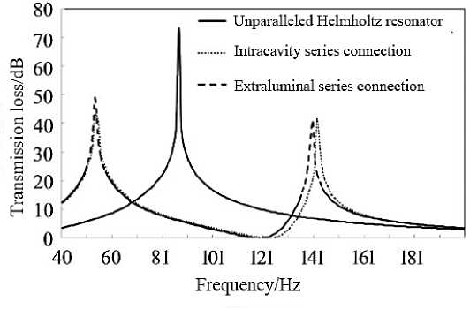
Figure 13. Transmission loss of Helmholtz resonator in series.
Conclusion
In this paper, the three-dimensional acoustic finite element method is used to calculate and analyze the acoustic characteristics of the Helmholtz resonance muffler, and the following conclusions are drawn:
-
1) When the connecting tube of the traditional Helmholtz resonator is extended into the resonator, the resonant frequency will be significantly reduced, and at the same time, the muffler frequency band will also be narrowed, when maintaining the total length of the connecting tube and the extension tube.
When the cavity position is moved along the center line of the connecting pipe, the resonance frequency is not affected much. When the extension tube contracts, the resonance frequency can be further reduced based on the original extension length, but the muffler frequency band will also be narrowed. This acoustical property, which can effectively reduce the resonance frequency without changing the external size of the resonator, is of great significance for engineering applications such as the ship internal pipeline system, where the space arrangement is very compact.
-
2) A parallel resonator with the same shape in the main road does not change the resonant frequency of the Helmholtz resonator, but the muffler frequency band is significantly wider; When a connecting pipe with the same shape is connected in parallel, the resonance frequency increases, and the muffler frequency band widens. When a resonator of the same shape is connected in series, two new resonators will be generated on both sides of the original resonator. Moreover, the connection of the resonator and the connection of the resonator has little influence on the acoustic
attenuation characteristics. According to the above acoustic characteristics, designers can combine the actual situation to design the resonators into a variety of complex series and parallel combination structures to meet the needs of wide muffler frequency band or excitation frequency change.
References Research of acoustically improved Helmholtz resonator
- Zhao Songling Noise reduction and insulation. Shanghai: Tongji University Press, 1989. P. 55-57.
- Li Zeng-gang, Zhan Fuliang. Virtual. Lab Acoustics, Advanced application of acoustical simulation and computation. Beijing: National Defence Industr Press, 2010. P. 49-59.
- Munjal M. L. Acoustics of ducts and mufflers. New York: A Wiley-Interscience Publication, 1987. P. 55-59.
- Ji Z. L. Acoustic length correction of closed cylindrical sidebranched tube // Journal of Sound and Vibration. 2005. V. 283. №3-5 P. 1180-1186. DOI: 10.1016/j.jsv.2004.06.044
- Ahmet S., Lljae L. Helmholtz resonator with extended neck // Journal of the Acoustical Society of America. 2003. V. 113. №4. P. 1975-1985.
