Research of Emergency Vehicles Information System Based on SOA

Author: Guangliang Li, Minghai Yao
Journal: International Journal of Computer Network and Information Security(IJCNIS) @ijcnis
Article in issue: 4 vol.3, 2011.
Free access
Using Service-Oriented Architecture (SOA) to build an information system is a hot topic at present. The primary goal of this paper is to investigate how to build a SOA-based information system in a special industry-the field of emergency vehicles in environment protection industry. The paper provides a presentation of current compositions of the emergency vehicles information system and then gives out the system structure. The paper proceeds with the business process flow and working principle of an emergency vehicle information system. A service-oriented architecture framework for emergency vehicles information system is proposed.
Service-oriented architecture, emergency vehicles, web service, system framework
Short address: https://sciup.org/15011031
IDR: 15011031
Text of the scientific article Research of Emergency Vehicles Information System Based on SOA
Published Online June 2011 in MECS
Along with the rapid development of Cloud Computing[1], SOC(Service-Oriented Computing) and SOA(Service-Oriented Architecture) are both highly valued by most of the IT companies and institutions for academic research more and more, also they get unprecedented development in the field of software engineering. From procedure-oriented scientific computing and proceduring software developing to object-oriented programming and component-oriented programming, each technique would combined with older ones’ advantages and abandon their’s disadvantages to make them better, and then SOA is coming. Compared with other distributed computing technology, such as Microsoft’s DCOM, SOA is not completely a new technology in this field[2]. However, SOA is the most important technology of the foundations of Cloud Computing’s basic concept and support technology, and it represents the new generation of distributed computing platform. SOA is a new kind of computing paradigm, which include new concepts, theories, and technical framework[3].
In the field of software engineering, SOA has been widely applied and is an ideal software architecture
Manuscript received April 3, 2011.
Supported by the Major Science and Technology Special Project of Zhejiang Province under Grant NO.2008C13017-2; the Natural Science Foundation of China under Grant NO.61070113.
design pattern in most professions. At present, however, the system applications based on SOA are limited in the fixed fields, such as banking, logistics, communications, electric power, etc. The purpose of this article is to provide a SOA-based solution for the Emergency Vehicle Information System (EVIS) in the environment protection field. Building an information platform for emergency vehicles is a valuable work at present and the progress may be maked slowly. In Finland, the emergency vehicles used by police, customs, frontier guards are increasingly dependent on ICT systems, especially wireless and mobile communications, and the information platform has been built completely at some respects[4]. In reference 4, the authors have shown an ICT integration solution for emergency vehicles, but that was only an abstract description. In this paper, combined with the real project, we give out a concrete solution for emergency vehicles information system based on SOA. And the key point is the solution framework for real business processing in environment protection field.
The content of this paper was arranged as follows. First, the paper introduces the summary of SOA and its application in software engineering is discussed. Then, the current situation of the emergency vehicles information system which is gradually implemented in the environment protection field is studied. We give out the problems of these systems. Emphatically, we propose the design scheme based on SOA of the emergency vehicles information system. Combining the business process flow, we studied the services’ design and the using method of the services.
-
II. S ERVICE -O RIENTED A RCHITECTURE
The W3C ( provides a good generic definition of a Service-Oriented Architecture (SOA) as a set of components that can be invoked and whose interface descriptions can be published and discovered. A web service is a specific instance of a component (or components) that has a public interface defined and described in XML and that other systems can discover and use by passing messages transported via existing internet protocols[5].
On the surface, the characteristics of SOA can be found in other distributed computing systems, but they have substantial differences. The significant difference between them is that each service (component) is loosely coupled, that is to say, the component that provides a service is an autonomous system. The communication from one service to another or from the service-requester to the service-provider are all completely based on open standard protocols, thus, the technical implementation of each component can be different. So, SOA is an architecture whose application is platform independent and technology independent, and this is the embodiment of its core value.
In a basic SOA model, there are three roles[6]:
-
• Service provider.
-
• Service broker.
-
• Service requester.
Service provider worked as a producer, which provides some valuable services for the customers. And the services’ implementations were all independent with others and they communicate with others by some contracts which were negotiated advanced. Service requester worked as the consumer which cals for some functions from the providers. Service broker played the role of a bridge, the providers and the requesters’ communication was implemented through the broker. Service provider registers some services’ contracts to the broker, and service requester search the concrete service that was needed from the broker.
These characteristics of SOA help it to gain the advantage that other similar systems cannot achieve: in completely off coupling systems, sharing information is easy to implement.
-
III. E MERGENCY V EHICLES I NFORMATION S YSTEM
-
A. Compositions
Emergency vehicles information system is a comprehensive platform which is in connection with environmental pollution accidents. Generally, it should include the following several subsystems [7]:
-
• Data center and data exchanging subsystem. This part provides the basic data and professional data such as environment protection departments’ data, GIS (Geographic Information System) data, resource data etc. It is the foundation of other subsystems.
-
• Forecasting warning subsystem. This part provides the functions to analysis the accident developing trend and forecast the pollution distribution in time and space dimensions and the occurrence probability of specific events.
-
• Digital response plan subsystem. This part generates the emergency treatment plan and implementation solution according to basic data and forecast data.
-
• Decision supporting subsystem. It can integrate many variable factors and contradictory factors to provide a decision supporting.
-
• Commanding and scheduling subsystem. This is used to issue instructions to coordinate personnel dealing with the pollution.
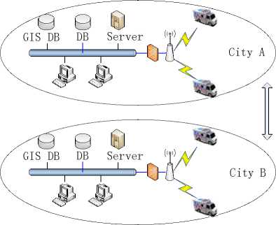
Figure1. The system framework of the EVIS.
-
• Feedback subsystem. It can be used to feedback data which is helpful to fix command giving out by the commanding and scheduling subsystem.
-
• Disaster evaluation subsystem. Using to evaluate the economic loss caused by the disaster.
-
• Training and drilling subsystem. Using to train the monitoring personnel and to exercise monitoring business.
-
B. System Framework
The current system framework of the emergency vehicles information system is shown in Fig. 1. There are two cities presented in the figure.
Fig. 1 illustrates how the emergency vehicle connect to the server where contain the core business processing procedure. All the business logic implementations and the data used to do the monitoring work are in the local area network system. An emergency vehicle information system’s 8 modules presented in the previous section are distributed in several DBs and servers. When the monitoring personnel worked with the vehicle, they deal with business through a wireless network which can be implemented by 3G mobile communication or GPRS service in 2G.
In this scheme, the content in the vehicle is just a client to request the server. The server will process all the important businesses, and the subsystems’ data is static since the data between several cities cannot be shared. Thus, the data center and data exchange subsystem, the digital response plan subsystem and other subsystems cannot actively integrate data to give out a more accurate result to help the personnel’s’ work. And this is a crucial respect, because the experiences and older cases’ information are significantly important for the current accident.
-
IV. A S ERVICE -O RIENTED A RCHITECTURE F RAMEWORK
-
A. Framework Transforming challenges
Considering the defects of the traditional framework of EVIS, we communicate with the emergency vehicles operation department and then attempt to transform the traditional framework to the SOA architecture.
TABLE I.
T HE L IST OF B USINESS F LOW
|
Business Flow |
Commanding personels |
Monitoring personel |
Decision personnel |
|
Receiving alarm |
• |
||
|
Device configuration |
• |
• |
|
|
Chemical search |
• |
• |
• |
|
Risk source search |
• |
• |
• |
|
Experts search |
• |
• |
• |
|
Cases search |
• |
• |
• |
|
Digital plan search |
• |
• |
• |
|
Real time data acquisiton |
• |
||
|
Spatial information search |
• |
• |
|
|
Pollution diffusion simulation |
• |
• |
|
|
Incedent forecasting |
• |
• |
|
|
Loss evaluation |
• |
• |
|
|
Resource schedualing |
• |
• |
|
|
Emergency decision |
• |
• |
|
|
Vehicles positioning |
• |
• |
|
|
Video monitoring |
• |
• |
|
|
History data statistics |
• |
||
|
Device knowledges search |
• |
• |
|
|
Asset managing |
• |
• |
However, there are some challenges among the transforming work.we need an effective and standard way to describe the emergency services so that they can play to their advantages. In daily operations of emergency vehicles, monitoring real-time data, basic data of the chemicals, risk source data, and pollution incidents cases data need an effective organizational form to use. On the other hand, pollution diffusion simulation system, spatial information support system should create good business models to achieve the goal.
-
B. Business Flow Architecture
Designing of the business flow architecture of EVIS is the basis of the whole framework. The construction of business flow architecture is a high-level designing work; it focuses on the participants of the flow, the participants’ activities, and the session among the participants.
To meet the goal of the emergency businesses, we need to designate the system-wides and determine the list of the business flow. Table 1 shows the list in EVIS.
Emergency business flow architecture related to emergency decision makers, emergency commanding personels, emergency schedualing personels and emergency monitoring personels, and each of them would use the local part of the business flow list. Emergency decision personels participate in the flows that are related to pollution loss more than others, the emergency commanding personels would interpose the monitoring personels’ activities. The monitoring personels are related with most of the business flows, their activities are most numerous and complex and cover almost all the flows. Also, they interact with other actors most closely and they are the final operater of the business processing.
C System Architecture
Since vehicles in the same city or in the different cities cannot share data which is helpful to monitoring the accident, we provide a SOA-based framework to deal with the problem.
As seen in the previous section, the subsystems should work together. In an emergency vehicles information system, the chemical information, risk source information, pollution monitoring cases information, digital response plan information, experts information, are the basis in the data center. And all above information can be shared between different accidents or different cities. In a real work, when the monitoring personnel finish his work, he could have not uploaded the real-time data to the server yet, and the experiences have not shared with other people too. And also the pollution monitoring cases information and the digital response plan information. So the vehicle should have a mechanism to share the information in the real time.
Unlike the traditional system framework, the vehicle in the system is not just a client at all. A very important reason why the data cannot be shared is that, the vehicle is just a requester. When the personnel use the system to
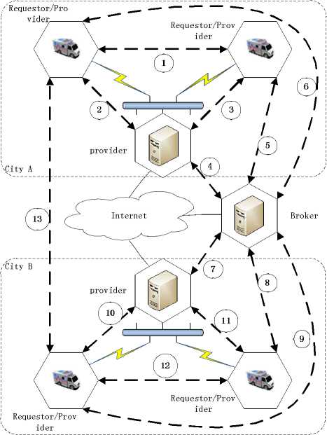
Figure2. The SOA framework for the EVIS.
help them to do the business work, they call the server through the client in the vehicle. Not only the vehicle in different cities but also the ones in the same city cannot share information. So, in the SOA-based framework, the vehicle plays a role like the server.
Fig. 2 shows the framework. In the framework, we explain how the vehicles in the same city or in different cities share information. There are some points:
-
• Each part can work alone as an autonomous system. The server provides services or data to the vehicles, the vehicles request the services and data provided by the server and also provide services to other part.
-
• Each part is in the network, they can connect to each other. The vehicles connect the network by a wireless communication, the server and the vehicles are in a LAN. The servers in different cities and the broker are connected by the internet.
-
• The broker is an intermediary. Each part except the broker can provide services and each vehicle can request services from the providers. The services provider register services in the broker and the services requester find them in the broker.
-
• The broker can belong to any city, or as a lonely one.
In section III, we have given out the composition of an emergency vehicles information system. In the SOA-based framework, the data center and data exchanging subsystem, the forecasting warning subsystem, the decision supporting subsystem, the commanding and scheduling subsystem are distributed in the server; the digital response plan subsystem, the feedback subsystem, the disaster evaluation subsystem, the training and drilling subsystem are distributed in the vehicle.
The numbers in Fig. 2 represent the data flows and the operation flows. The service providers register and publish services in the service broker, and the service requesters find the services also in the broker. Then the requester binds the service which is needed to the provider.
The numbers 4,5,6,7,8,9 in Fig.2 show that each component in the framework publishes services in the broker. So the broker has storage of all the subsystem’s services. The numbers 5,6,8,9 show that the vehicles find services from the broker. The numbers 1,2,3,10,11,12,13 show that service requesters use services from the providers after binding the services.
D Technical Gradation Architecture
The system architecture discussed in the previous section is the top system framework; here we provide the technical framework for the elements which composed to the whole architecture.
Fig.3 shows the technical gradation architecture of each component in the SOA framework. Each component which is ether the service provider or the service requester would be a self-governing system, and would use the gradation mode.
On the bottom level, there is the resource layer which is used to provide the basic data and save them, and it will provide some interfaces for the up layer to call for
HTML Ajax RIA
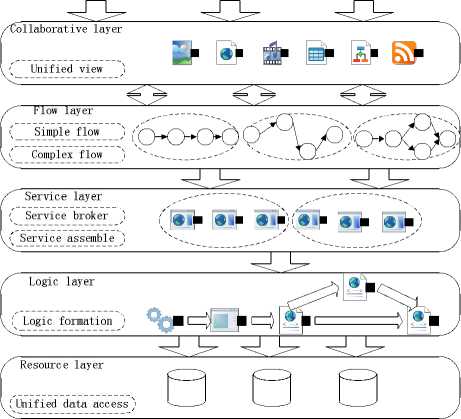
Figure3. The technical gradation architecture.
some functions. On top of the resource layer there is the logic layer which implements the concrete business. It is the core of the service that is provided for other components. So, above the logic layer, that is service layer. And above the service layer, there is the flow layer which is the business’s processing procedure. The flow layer would call for functions from the local service layer and the remote service layer. On the top of the gradation is the collaborative layer which is the user’s interface to provide some unified views, so that the final users who are from the different distributed nodes would have unified using feelings.
-
V. S ERVICE M ODELING
-
A. Services Overview
The services provide by the EVIS’s different part also involve different respects since the nodes’ physical positions and network positions are not the same. The whole information system’s services are shown in Fig.4. The vehicle node’s service inventory includes realtime data service, incident case service, digital plan service
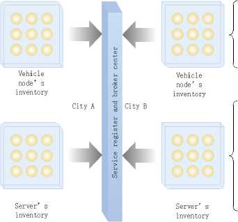
Figure4. The services in each part.

Realtime data service
Incident case service
Digital plan service
Asset using service
Chemical service
Risk source service
Expert data service Diffusion simulation service Spatial data service estimate service
TABLE II
T HE L IST OF S ERVICES
|
Services’ Name |
Services’ Interfaces |
Description |
|
Incident case service |
CaseManage |
Vehicle, server |
|
GetData |
Vehicle |
|
|
Digital plan service |
PlanManage |
Vehicle, server |
|
GetData |
Vehicle |
|
|
Asset using service |
ResourceManage |
Vehicle, server |
|
GetState |
Vehicle |
|
|
GetDetail |
Vehicle |
|
|
Chemical data service |
MaterialManage |
Server |
|
GetPhysChem |
Server |
|
|
GetHealthHarm |
Server |
|
|
GetDangProp |
Server |
|
|
GetEnvironmentalStandard |
Server |
|
|
GetMonitoringMethod |
Server |
|
|
GetProtection |
Server |
|
|
GetFirstAid |
Server |
|
|
Risk source service |
EntDMManage |
Server, Vehicle |
|
GetEntInfo |
Server, Vehicle |
|
|
GetDMUsing |
Server, Vehicle |
|
|
GetDM |
Server, Vehicle |
|
|
Expert data service |
ExpertManage |
Server |
|
GetExpert |
Server, Vehicle |
|
|
GetProfessionalField |
Server, Vehicle |
|
|
Diffusion simulation service |
GetSunDetail |
Server |
|
GetAirDetail |
Server |
|
|
GetWeatherDetail |
Server |
|
|
GetModelDetail |
Server |
|
|
GetSimulationMap |
Server |
|
|
GetMiddleParameter |
Server |
|
|
Spatial data service |
GetLongitude |
Server, Vehicle |
|
GetLatitude |
Server, Vehicle |
|
|
GetMap |
Server |
|
|
Loss estimate service |
GetAirModel |
Server |
|
GetWaterModel |
Server |
|
|
GetSolution |
Server |
and asset using service; the server node’s service inventory includes chemical data service, risk source data service, expert data service, diffusion simulation service, spatial data service and loss estimate service.
Table II shows the services’ interfaces and where can get the contracts of the services. As shown in Fig.3, these interfaces are in the third layer of each node component, and they can be found by other service requesters distributed in local node or in remote nodes.
-
B. Services Modeling
The 8 subsystems’ components have several services to support the whole emergency vehicles information system. According to [8][9][10], here we introduce the services that the forecasting warning subsystem provides.
-
1) GIS Service. To provide a intuitive presentation of the pollution diffusion simulation, the GIS(Geographic Information System) is needed.GIS service provides the functions like getting map, getting layer, getting table, routing, encoding and so on.
-
2) Diffusion Model Service. The service provides the functions like Gaussion Model Formula, air concentration computing, contour line point computing.
-
3) Meteorological Service. The service provides the functions like getting sun elevation angle, getting sun inclination angle, getting sun radiation level, getting air steady level.
-
4) Realtime Data Service. The service provides the functions like gett data of the pollution, getting parameters, getting data unit, getting monitoring time, getting pollution id, getting monitoring position, getting sampling rate.
The realtime data service’s model is shown in Fig.5. Realtime data is the basic service of the forecasting warning subsystem, it should include some interfaces or contracts shown to others. The vehicle’s ID and the chemical parameter’s ID would be the core data of the call message in the using of the realtime data service, sometimes the monitoring time is also the needed data.
-
C. Data Integration
In the emergency vehicles information system based on SOA, data integration is the basis to achieve the goal of executing the emergency services. In the daily business processing, the data forms are complex which include structured data and unstructured data. And in these data forms, the relational data are the most conventional data form that can be transformed to XML easily. Fig.5 shows the exchanging between Dataset and XML. Dataset is the usual form to explain the data between the database and the programming language such as C#, and it can be processed by most of the languages and most of the
DataSet
DataTable
( DataTable
( DataTable
DataRow
(DataColumn (DataColumn (DataColumn
( DataRow
( DataRow
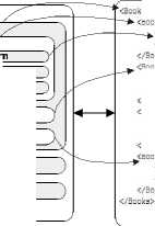
«Волк ISBN="0553212419"S
«authorsStephen E. Ambrose

databases. Form Fig.5, we can find that the structures between dataset and XML text are similar. We can use a built-in mechanism in C# to converse the data to XML text.
Fig.5 just shows dataset to XML’s transforming method, and data integration is not only resolve the data that structured as dataset but also structured as other more complex forms, such as internet page DOM and Word document. All these data should transform to XML text so that the data in the emergency vehicles information system structured as a uniform structure and then we achieve the goal.
VI. SERVICE DISCOVERY AND COMPOSITION
After all components register their services in the service broker, the vehicle can find a matched service from the broker. For example, to forecast the pollution diffusion, it should find Diffusion Model Service and GIS Service. The GIS Service can be found which provided by the server component, then the vehicle bind the service to the server. However, the Diffusion Model Service needs some services to help it to finish the task. In this case, the services should be composited. The Diffusion Model Service, the Meteorological Service and the Real-time Data Service would composite to a new one which can provide matched services.
Service broker is the most important part in the whole system which provides the business processing logic of service discovery and composition.
Fig.6 shows the constructure of service broker. It includes a service register table to save the service contract that the service provider published in it, and the register table is the core of the broker. Each service provider should publish its service contracts to the broker through a SOAP message, and each service requester should find the services that it needed from the broker also through a SOAP message.
The service composition is processed base on the service discovery. When a service requester needs a service that not included in the register table, it would
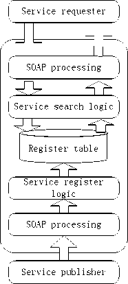
Figure6. The Constructure of Service Broker.
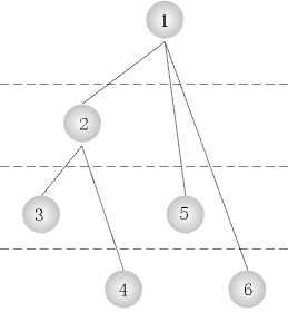
Figure7. The Method to Ensure the Composition’s Correctness.
divise the function to some small services that included in the register table, and find all the small services from the register table and compose them to a complete service.
To ensure the correctness of the service composition, we proposed a new method to get it. A complex big service needs to decompose to some small simple services so that the processing procedure can be executed. When it has been disintegrated, we marked it and marked the sub-services so that we can know the sequence of the services’ composition. Fig.7 shows the principle of the processing.
VII. AN EXAMPLE
Fig. 8 shows the representation of a business processing procedure that how to simulate the air pollution diffusion.
In the field of environment monitoring, the processing of pollution diffusion simulation is a hard work since there are plenty of parameters in the processing procedure and the factors are always changeful. So monitoring personnel should work with not only the data that can get by themself but also the data that get from other personnel who were in the different vehicles or in the different cities.
The procedure of pollution diffusion simulation should supported by the GIS service, the meteorological service, the diffusion model service, and the real-time data service. The vehicle system finds the services from the services broker. A situation would happen that the meteorological service in local vehicle do not matched the requirement, and the GIS service is not in the local vehicle. Then the vehicle system would find another service that is suitable. As shown in Fig.4, the services from the local vehicle, the remote server and other vehicles would be composed to another and a service would invoke other services to match the requirement.
The components that request the services would send SOAP messages to the service providers after binding services. The meteorological service and the real-time data service supply parameters to the diffusion model service, and it would feedback the diffusion information after computing. All these information then send to the GIS service by SOAP messages. The GIS service component would draw some curve on the GIS map.
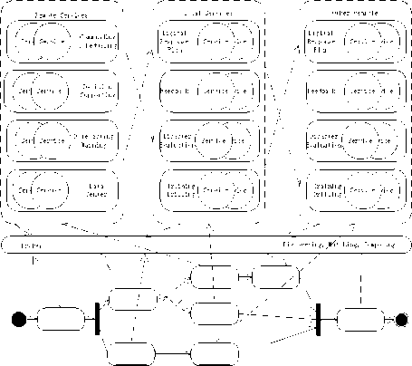
Figure8. An example of Business Processing.
After that, the service of pollution diffusion simulation is invoked completely.
VIII. CONCLUSION
This paper addressed the application of SOA in the field of emergency vehicle information system. The traditional framework was discussed. Particularly, we proceed with the composition of a standard emergency vehicle system. The core of this paper is to propose a Service-Oriented Architecture Framework for emergency vehicles information system. The details of the framework were discussed and also an example of business processing in the framework was proposed.
References Research of Emergency Vehicles Information System Based on SOA
- Michael Armbrust, Armando Fox, Rean Griffith, Anthony D. Joseph, Randy Katz, Andy Konwinski, Gunho Lee, David Patterson, Ariel Rabkin, Ion Stoica, Matel Zaharia. A View of Cloud Computing[J]. Communications of the ACM, 2010, 53(4), 50-58.
- Do van Thanh, Ivar Jorstad, “A Service-Oriented Architecture Framework for Mobile Services,” Advanced Industrial Conference on Telecommunications/Service Assurance with Partial and Intermittent Resources Conference/E-Learning on Telecommunicatins Workshop, July 2005, pp. 65-70, doi:10.1109/AICT.2005.14.
- Michael p. Papazoglou, Paolo Traverso, “Service-Oriented Computing: State of the Art and Research Challenges,” Coputer,vol.40,Nov.2007,pp.38-45, dio:10.1109/MC.2007. 400.
- Jyri Rajamaki, Timo Villemson. Creating a service oriented architecture model for emergency vehicles[J]. International Journal of Communications,2009,2(3),44-53.
- Nicolas Gold, Andrew Mohan, Claire Knight, Malcolm Munro, “Understanding Service-Oriented Software,” Software, Vol.21, April 2004, pp.71-77,doi:10.1109/ MS.2004.1270766.
- Ning Gu, Jiamao Liu, Xiaolu Chai, Web Services Principles, 1st ed., Beijing: China Machine Press, 2006, pp.69-90. (in Chinese)
- Chaoyang Fu, Qinxian Jin, “Research on the General Framework and Composition of Environment Emergency Management Information System,” Environmental Monitoring in China, vol.23, Oct. 2007, pp. 82-86. (in Chinese)
- Thomas Erl, SOA: Principles of Service Design, 1st ed., London: Pearson Education, 2008, pp.18-69.
- Paul C. Brown, Implementing SOA: Total Architecture in Practice, 1st ed., London: Pearson Education, 2008, pp.63-158.
- Zhiyi Ma, Hongjie Chen, “A Service-Oriented Architecture Reference Model,” Chinese Journal of Computers, vol.29, July 2006, pp. 1011-1019. (in Chinese)
