Research of the method based on the influence of sound waves on the metal-mesh for measuring the tension force of the metal-mesh on large-sized reflectors

Author: Gracheva E.A., Sin’kovskiy F.K., Snytko D.V., Zamyatin D.A.
Journal: Siberian Aerospace Journal @vestnik-sibsau-en
Section: Aviation and spacecraft engineering
Article in issue: 1 vol.23, 2022.
Free access
The article provides an overview of current methods for measuring and controlling the tension force of the material of the spacecraft metal-mesh reflectors. The purpose of the research: to obtain the most accu-rate results of measuring the mesh tension. Based on the review, a comparative analysis of the advantages and disadvantages of each of the considered methods was carried out, when measuring the tension force on mesh for large-sized transformable spacecraft reflectors. In the article considered the methods of force measurement: photo method, the operation principle of which consists in the sequential photographing of a mesh on reflector frame certain zones; a method based on pattern recognition, similar to the photo method, but using an information and measurement system with a given information processing algorithm; a meth-od based on local membrane deformation, related to the contact type, in which the mesh tension measure-ment is defined as a reaction from the impact of physical force on the mesh surface; a method based on the influence of sound waves impact, which is based on the influence of sound waves impact on the mesh sur-face. The experimental part of the research described in the article includes the measurement of the mesh tension by the resonance method, as the most optimal method according to the analysis. The prospects of possible use of the resonance method in the aerospace industry of radio-reflecting surfaces of spacecraft antennas are proposed and analyzed. According to the results of the conducted research, the dependence of tension force of mesh is established on the sound vibrations frequency affecting the mesh, at which reso-nance occurs.
Reflector, radio-reflective surface, metal-mesh, metal-mesh tension force, flat deformable membrane
Short address: https://sciup.org/148329608
IDR: 148329608 | UDC: 681.2.083:629.7.024.54-427.5 | DOI: 10.31772/2712-8970-2022-23-1-64-72
Text of the scientific article Research of the method based on the influence of sound waves on the metal-mesh for measuring the tension force of the metal-mesh on large-sized reflectors
Currently, one of the trends in the development of satellite space antennas is the development and creation of a reflective surface for antennas with aperture diameters from four to several tens of meters [1; 2].
To create such a reflective surface, a textile metal-mesh of various grades of material and types of wire weave is used.
The necessary geometric parameters of the antenna reflector surface profile depend, among other things, on the magnitude and uniformity of the tension of the mesh strip over the entire diameter of the reflector aperture in the working position [3-5].
Also, the amount of tension of the metal mesh has a significant effect on the reflective characteristics of the antenna and the uniformity of the antenna opening in the space environment [6-8].
This article discusses the contact and non-contact methods used in practice to measure the tension of the mesh of large-sized transformable antenna reflectors.
Photo method
Photo method refers to contactless methods and is the easiest to implement. The principle of
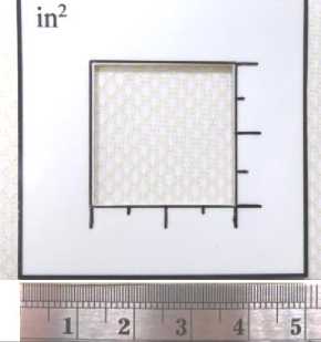
Fig. 1. Determination of the number of mesh cells by the photo method*
Рис. 1. Определение количества ячеек на сетеполотне фотометодом**
operation of this method consists in the sequential photographing of certain zones of a stretched mesh on the frame of the reflector. The number of zones is determined by the diameter of the reflector. In the place of each zone, a frame with an area of x 25-25 mm is superimposed, after which the frame is photographed. Then, using a computer image processing program, the scale of the photo is increased and the number of cells is recalculated in length and width (Fig. 1), after which the result is compared with the prestored values on the mesh pattern [9; 10]. *****
A method based on pattern recognition
The method based on pattern recognition allows to eliminate the drawbacks of the photo method [11]. The principle of operation of this method is similar to a photo method, but an information-measuring system with a given information processing algorithm was created to automate the process [12]. The algorithm of operation of this system is based on specialized software for the analysis of photographs and automated counting of the number of cells. Despite such advantages as ease of implementation and speed of processing results, the image recognition method has several significant drawbacks.
Firstly, this method does not give a full assessment during the control of the tension force of the mesh on the reflector, since the method does not show the actual numerical value of the force with which the mesh is stretched, which greatly complicates the calibration of the tension force of the mesh when mounting the mesh on the reflector and ensuring a given tension force.
Secondly, when the mesh is reached at the moment of stretching a certain tension force (different for each brand of the mesh), the linear dimensions of its cell cease to change (Fig. 2), and, accordingly, it is impossible to determine the magnitude of the tension force of the mesh in the "stretched" state. This affects the strength of the mesh in the working position of the reflector and the unevenness of the radio-reflecting surface due to zonal tentions in local zones.
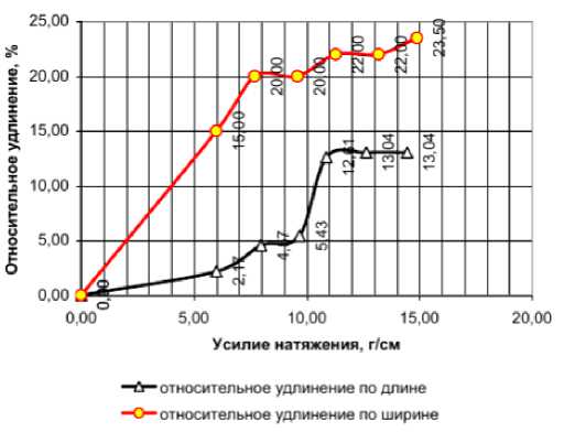
Fig. 2. Dependence of the relative elongation of the mesh surface on the tension force
Рис. 2. Зависимость относительного удлинения поверхности сетеполотна от усилия натяжения
Method based on local deformation of the membrane
This method belongs to the contact type, in which the measurement of the tension of the mesh is defined as a reaction from the impact of physical force on the surface of the mesh.
To date, among such measurement methods, a method based on local deformation of the mesh membrane is known and used in practice [13-15].
Mesh as a structural element of a satellite antenna has practically no bending stiffness and can be considered a membrane.
The method consists in pinching the membrane with two rings located on different sides of the membrane surface, and applying a transverse load distributed over the area of a circle which center coincides with the centers of the pinching rings (Fig. 3), measure the maximum deflection of the membrane and determine the uniform tension of the membrane according to the formula а=Р2Шя п =
p
2 IH п ;
b

d
V1 + h 2 в2
1 rB 2
r b 4 1 + H 2 B 2

4 b2 r2 In r- + 2 b2 (d2 + r2) - 2 r2 (b2 + d2) b b4 - d 4 + 4 b2 d 2ln d
b
где σ – величина равномерного натяжения мембраны, Н/м; Р – величина поперечной нагрузки, Н; Н – величина максимального прогиба мембраны, м; b – внутренний радиус защемляющих колец, м; d – радиус круговой площадки, по которой распределена нагрузка, м; r – переменная интегрирования, имеющая смысл радиальной координаты, м.
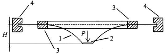
Fig. 3. Device for determining the tension of the mesh by the method of local deformation of the membrane:
1 – the membrane; 2 – the platform on which the load is distributed; 3 – the clamping rings; 4 – the outer boundary of the membrane
Рис. 3. Приспособление для определения натяжения сетеполотна методом локальной деформации мембраны:
1 – мембрана; 2 – площадка, по которой распределена нагрузка;
3 – защемляющие кольца; 4 – внешняя граница мембраны
This method formed the basis of the developed device for controlling the uniformity of the tension force of the net, schematically shown in Fig. 4.
The device consists of a support ring ( 6 ) rigidly fixed with spokes ( 5 ) on a cylindrical tube with a measuring scale ( 2 ), along which a rod ( 3 ) moves freely, at one end of which a weighted tip ( 4 ) is fixed, and at the other end an needle ( 1 ) moving along the scale is fixed.
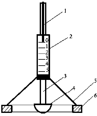
Fig. 4. Device for controlling the tension force of the mesh:
1 – needle; 2 – scale; 3 – rod; 4 – tip;
5 – spokes; 6 – support ring
Рис. 4. Приспособление для контроля усилия натяжения сетеполотна:
-
1 – стрелка; 2 – шкала; 3 – стержень;
-
4 – наконечник; 5 – спицы;
6 – опорное кольцо
Despite its simplicity and practicality, this device can only be used on a flat surface and is not suitable for controlling the uniformity of tension on reflectors having a curved surface. Also, the method using this device is an estimate, since it does not show the actual measured value of the tension force. To determine the actual values, a recalculation is necessary, which in turn is very laborious.
Due to the disadvantages of the above methods, none of them fully meets the requirements for measuring and controlling the tension force on the mesh.
A method based on the influence of sound waves
Taking into account the disadvantages of the above methods of measuring the tension of the mesh, we propose a new method based on the influence of sound waves on the surface of the mesh.
We will proceed from the assumption that the mesh is a membrane bounded on four sides. Then, like any other membrane, the mesh should have its own frequency of free oscillations. This, in turn, means that if sound waves of different frequencies are applied to the mesh, then at some point the frequency of the wave from an external source will coincide with the natural frequency of free oscillations of the mesh, which will lead to resonance.
So, depending on the tension force of the mesh, the natural frequency of free oscillations will also change, which will also change the resonant peaks that occur when the frequency of sound waves from an external source coincides with it. The moment of occurrence of resonant
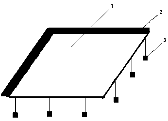
Fig. 5. Mesh with evenly distributed load: 1 – mesh; 2 – rigid fastening; 3 – loads
peaks will be possible to measure using sensors.
To confirm these theses, tests were carried out to study the effect of the tension force of the mesh on the frequency of sound vibrations at which resonant peaks occur.
In the study, a mesh 1 (Fig. 5) with a size of 17 x 17 cm was used, rigidly fixed to the frame from two perpendicular sides 2 . 3 loads were evenly suspended on the other two sides, creating a uniform tensile load on the mesh.
The tension force of the mesh, arising under the action of the load, was calculated by the formula
У m
a=ml o = , (4)
where σ is the tension force of the mesh, g/cm; У m m - the total weight of loads per side, g; l is the length (width) of the mesh, cm.
Figure 6 shows the layout of the equipment for testing
In the middle of the mesh 1 , a magnet 2 was fixed, above which a microphone 3 , consisting of a coil and a permanent magnet, was located at a distance of approximately 5 mm. The microphone was connected to a multimeter 4 . A sound amplifier 5 was installed under the mesh, which was connected to a sound frequency generator 6 .
Рис. 5. Сетеполотно с равномерной распределенной нагрузкой:
1 – сетеполотно; 2 – жесткое крепление;
3 – грузы
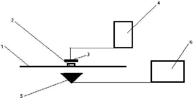
Fig. 6. Layout of test equipment:
1 – networked; 2 – magnet; 3 – microphone; 4 – multimeter; 5 – sound amplifier; 6 – sound frequency generator
Рис. 6. Схема расположения оборудования для проведения испытаний:
1 – сетеполотно; 2 – магнит; 3 – микрофон; 4 – мультиметр;
5 – усилитель звука; 6 – генератор звуковых частот
Under the influence of sound waves from the sound amplifier, the mesh began to make oscillatory movements, which led to the appearance of an alternating magnetic field on a magnet fixed to the mesh. At the same time, under the influence of an alternating magnetic field, an
EDF appeared on the microphone coil. The EDF value was output to the multimeter in millivolts.
By adjusting the sound frequency on the sound frequency generator, the resonant frequency was determined at the moment when the EDF data on the multimeter were maximum.
Thus, 12 measurements were carried out. For each measurement, the load on each side of the mesh was increased by hanging additional loads. After each loading of the mesh, the maximum data were taken from the multimeter and the frequency at which the resonance occurred was recorded.
The results of the dependence of the resonant frequency of sound on the tension force of the mesh are shown in the table.
The results of the dependence of the resonant frequency of sound on the tension force of the mesh
|
Measurement No. |
Total weight of cargo per side (m), g |
Side tension force (a), g/cm |
Resonant frequency (µ), Hz |
EMF(v max ), mV |
|
1 |
50 |
2.9 |
83 |
0.25 |
|
2 |
70 |
4.1 |
84 |
0.21 |
|
3 |
90 |
5.3 |
85 |
0.21 |
|
4 |
100 |
5.9 |
85 |
0.20 |
|
5 |
115 |
6.8 |
86 |
0.19 |
|
6 |
133 |
7.8 |
87 |
0.19 |
|
7 |
149 |
8.8 |
90 |
0.20 |
|
8 |
165 |
9.7 |
92 |
0.19 |
|
9 |
182 |
10.7 |
104 |
0.40 |
|
10 |
198 |
11.7 |
107 |
0.40 |
|
11 |
215 |
12.6 |
110 |
0.42 |
|
12 |
231 |
13.6 |
115 |
0.40 |
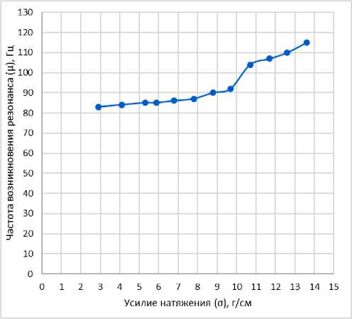
According to the results of the experiment, the dependence of the frequency of sound vibrations at which a resonance occurs on the tension force of the mesh is revealed (Fig. 7). The frequency at which resonance occurs increases with increasing tension force.
-
Fig. 7. The dependence of the resonant frequency of sound vibrations and the EMF value at the moment of resonance on the tension force of the mesh*
Рис. 7. Зависимость резонансной частоты звуковых колебаний и величины ЭДС в момент резонанса от усилия натяжения сетеполотна**
Conclusion
According to the results of the conducted research, the dependence of the tension force of the mesh is established on the frequency of sound vibrations affecting the mesh, at which resonance occurs.
It should be noted that a significant disadvantage of this method is the impossibility of its application directly on the reflector due to non-technological nature.
However, this method can be applied at the manufacturing stage of individual segments of the mesh after their installation in a technological device in order to ensure the working tension of the segments of the mesh.
References Research of the method based on the influence of sound waves on the metal-mesh for measuring the tension force of the metal-mesh on large-sized reflectors
- Klishev O. P., Halimanovich V. I. [Analysis of elastic deformations of the spacecraft on the dis-tortion of the shape of the reflecting surfaces of large-sized structural elements]. Vestnik SibGU. 2008, No. 1 (18), P. 115–118 (In Russ.).
- Halimanovich V. I., Kudryavin L. A., Belyaev O. F., Zavaruyev V. A. [The use of the nonlinear theory of elasticity and the similarity method for assessing the deformation properties of metal-mesh netting]. Bulletin of Tomsk State University. Mathematics and mechanics. 2017, No. 49, P. 105–113 (In Russ.).
- Lubrano V., Mizzoni R., Silvestrucci F., Raboso D. PIM characteristics of The Large Deployable Reflector Antenna Mesh. 4th International Workshop on Multipactor, Corona and Passive Intermodu-lation in Space RF Hardware, 2003 Available at: http//:www.estec.esa.nl/ conferences/03C26.
- Zhukov A. P. [Reaction of the reflecting surface of a large-sized reflector to the action of a per-turbing pulse]. Bulletin of Tomsk State University. Mathematics and mechanics. 2011, No. 4 (16), P. 101–109 (In Russ.).
- The program for determining the shape of the cutting of the axisymmetric reflector. No. 2019619521: application 31.07.2019, publ. 07.08.2019. Bukhtyak M. S., Ponomarev S. A. (In Russ.).
- Lavrushev V. N., Gilyazov I. I. Improving the accuracy when measuring the reflection coeffi-cient of the net. Materials of the International Scientific and Technical Conference of Young scientists, postgraduates and students. Edited by Ivanov A. A. 2018 (In Russ.).
- Romanov A. G., Sedelnikov Yu. E. Measurement of the reflection coefficient of mesh materials // Bulletin of Kazan State Technical University named after A. N. Tupolev.2013, No. 1, P. 81–85 (In Russ.).
- Patent No. 2350518 C1 Russian Federation, IPC B64G 1/22, H01Q 15/16. Method of manufac-turing a deployable large-sized reflector of a spacecraft. No. 2007122181/11, application 13.06.2007, publ. 27.03.2009. Testoedov N. A., Halimanovich V. I., Shipilov G. V. [et al.].
- Soifera V. A. Metody komp'yuternoy obrabotki izobrazheniy [Methods of computer image pro-cessing]. Moscow, Fizmatlit Publ., 2001, 784 p.
- Grishentsev A. Yu., Korobeynikov A. G. Metody i modeli tsifrovoy obrabotki izobrazheniy [Methods and models of digital image processing]. St. Petersburg, 2014,190 p.
- Sukharev E. N., Kolovsky Yu. V. [Method for determining the tension of the antenna grid based on pattern recognition]. Vestnik SibGU. 2006, No. 1(8), P. 96–100 (In Russ.).
- Sukharev E. N., Kolovsky Yu. V. The program of image processing of the antenna metal-mesh for determining its tension. Сertificate of official registration of the computer program No. 2005612186/ M., 2005 (In Russ.).
- Patent No. 216.012. 7AS2 method for determining the uniform tension of a membrane made of an isotropic material. Zhukov A. P., Pavlov M. S., Podshivalov S. F., Ponomarev S. V., Halimanovich V. I.
- Patent No. RU 2427948 C1 The umbellate antenna of the spacecraft. Testoedov N. A., Halima-novich V. I., Velichko A. I., Shipilov G. V., Kolesnikov A. P., Akchurin V. P.
- Zhukov A. P., Pavlov M. S., Podshivalov S. F., Ponomarev S. V., Halimanovich V. I. Indenta-tion of the indenter into the surface of a stretched metal-mesh. Bulletin of the Tomsk State University. 2010, No. 4 (12), P. 96–101 (In Russ.).
