Research of the ways to increase the accuracy of the mirror milling machining of the waffle grids by means of the digital correction techniques

Author: Pas O.V., Serkov N.A.
Journal: Siberian Aerospace Journal @vestnik-sibsau-en
Section: Technological processes and material science
Article in issue: 2 vol.23, 2022.
Free access
Waffle shells are the main part of the overall dry mass of the products of the aerospace industry. Cell bottom thickness and the width of the longtitudal and circular edges are the main characteristics of the waffle grid. Mechanical cutting by using of the machine tools of SVO series which perform tracking and copying of the opposite wall thus providing the stability of the bottom thickness despite of the workpiece shape errors is the most wide-spread technology of the manufacturing of the waffle grid. There are different other factors which act during such a process and lead to bottom thickness and edge width errors which brings to increase of the weight of the part, use of the additional finishing operations and rise of the defects amount during milling process. Thus it is essential to solve the problem of the increase of the machining accuracy of the cell thickness bottom, which might cause the rise of the machining performance and might help to raise the quality of waffle shells. In order to do this, authors examine in detail the waffle grid mirror milling manufacturing process. The factors which lead to the cell bottom thickness deviations were described and classified. It was analyzed and shown in the paper that deviations of the spindle axis against the surface normal affect the magnitude of cell bottom thickness errors. Authors also perform the mathematical modeling of cell bottom thickness errors because of presence of backlash in tracking system. The paper presents a detailed description of various techniques to increase the machining accuracy of the cell bottom. It was demonstrated that the most suitable is to use the combined digital compensation method by using of self-tuning system. Implementation of the solution will enhance the mass-energy properties of the aerospace products by means of decrease of the overall dry mass by attainment the higher cell bottom machining accuracy. It also will bring to raise of the quality and reliability of production by reducing the defects amount. The mirror milling machining process was considered. The factors leading to the thickness er-rors of the pocket bottoms were classified. Perfomed the simulation of the thickness errors genera-tion caused by the influence of the most significant factors. Techniques to increase the accuracy during machining of the pocket bottoms were analysed, provided the reason of using the combined digital correction method with self-tuning from pass to pass.
Mirror milling, waffle grid, large thin-walled parts, digital compensation algorithm, postprocessor
Short address: https://sciup.org/148329630
IDR: 148329630 | UDC: 621.87 629.78 | DOI: 10.31772/2712-8970-2022-23-2-321-336
Text of the scientific article Research of the ways to increase the accuracy of the mirror milling machining of the waffle grids by means of the digital correction techniques
Wafer shells [1; 2] are thin-walled cylindrical, conical or spherical shells with a grid of reinforcing ribs. Wafer shells are the main load-bearing elements of the bodies of products of rocket and space technology (RCT), together making up the bulk of the "dry" mass of the product. The use of wafer shells provides maximum strength characteristics with a minimum weight of the structure [3–5].
To achieve high mass and strength characteristics of the product, increased requirements are imposed on the accuracy of processing the residual fabric and pocket edges of wafer shells [6].
These requirements, along with the features of structures that have a waffle background and are expressed by low rigidity with large overall dimensions of workpieces, determine the use of specialized processing methods and algorithms [7], aimed at compensating for errors in the shape of the work- piece, deformations and other factors that lead to deviations of the actual thickness of the residual fabric from the specified one. The authors of [8] propose to calculate and correct milling errors of thinwalled parts using the tool and workpiece deformation model based on the finite element method. In [9], an analytical model of cutting forces and the ANSYS environment are used to calculate deformations during milling of non-rigid parts. The work [10] presents a model for calculating shape errors arising from the deformation of the workpiece during 5-coordinate milling of engine blades. The model can be used to generate a corrected toolpath during processing. The authors of [11] propose to use a laser sensor to measure and build a model of the actual surface of a deformed thin-walled workpiece before processing, which is used to calculate correctors and predistort the part processing trajectory. Article [12] describes the technology of milling the wafer background of the shell using a laser sensor that measures the coordinate of the opposite wall to calculate and correct deformations of the workpiece in real time. In [13], in order to improve the accuracy of processing the residual blade, the authors propose a new strategy for processing a thin-walled product of the “bottom” type, the essence of which is to correct the reference points of the control program, taking into account the actual geometry of the workpiece surface and deformations during the cutting process. The actual surface geometry is calculated before machining on the basis of measurement data from the touch probe and the ultrasonic probe. Deformations during the cutting process are calculated based on a predictive model, the parameters of which are determined by the results of measurements of the sheet thickness after the previous pass. In [14], the support vector machine is used to classify errors according to the thickness of the residual web for static errors depending on the position of the tool in the working area and dynamic errors that change over time, algorithms for compensating both types of errors are proposed. In [15], it is proposed to improve the accuracy of processing thin-walled products with rows of pockets by calculating correctors based on a model built on the principles of machine learning.
However, it should be noted that today mirror milling [16; 17] is the most efficient technology for machining thin-walled shells in terms of accuracy and performance. With the domestic approach, one of the main methods for the production of wafer shells is mirror milling of the rolled surface of the shell on HPPS type machines (high-precision processing system) [18].
The technology for processing the wafer background on HPPS machines provides compensation for errors in the installation and shape of the workpiece and increases the vibration resistance of the MFTP system (machine, fixture, tool, part) through the use of a follower support that acts as a movable stop and a copy head that tracks the back workpiece wall.
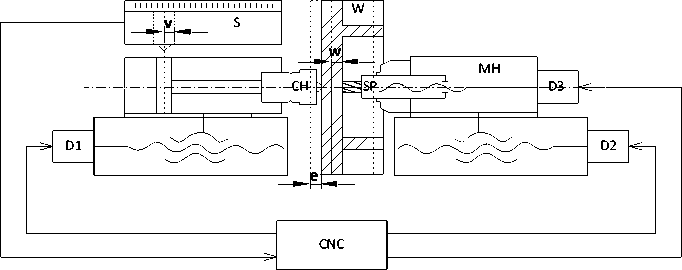
Рис. 1. Схема выполнения зеркального фрезерования вафельного фона
Fig. 1. Waffle grid mirror milling process scheme
Figure 1 shows a diagram of the mirror milling of a waffle background on HPPS type machines. In this case, the drives P1 and P2 carry out synchronous movement according to the control program (CP). Sensor D, built into the copy head CH, monitors the movement of the pneumatic cylinder rod; the signal V from the sensor enters the numerical control system (NCS), which corrects the position of the milling head with the Ш spindle, setting the corrective action W to the drive of the axial movement of the milling head P3 depending on the deviation of the inner surface of the workpiece Z from the opposite side.
Despite the compensation of errors in the installation and shape of the workpiece during the processing of the wafer shell on the HPPS machine, the influence of a number of factors in the process of mirror milling the wafer background leads to deviations in the thickness of the residual fabric and the width of the longitudinal and annular pocket ribs. As a consequence, this leads to an increase in additional masses of the product and the need to perform finishing operations using energy-intensive and labor-intensive electrophysical processing methods [19]. Therefore, the development of methods for improving the accuracy of processing the residual fabric and pocket edges is an important area of research. This paper presents the results of a study of possibilities of improving the accuracy of mechanical processing of the wafer background using software correction methods.
In the course of the research, particular tasks were solved:
-
1. The main factors causing deviations of the residual fabric, and the degree of this influence are considered.
-
2. Methods for increasing the accuracy of machining the surface of the pocket (residual fabric) are investigated and an analysisof ways to improve the accuracy of machining, primarily in relation to improving the accuracy of machining the bottom of the pocket, is given.
-
3. Existing wafer background processing technology is proposed to improve by applying a combined correction system (a self-adjusting system with disturbance correction).
Factors affecting the accuracy of processing on the residual fabric
Groups of factors. With the processing scheme (Fig. 1), nine main factors leading to deviations in the thickness of the residual fabric can be distinguished (Fig. 2), The main perturbations in the processing of a waffle background product are:
-
1) insufficient rigidity (structurally justified) and its heterogeneity for individual cells (elements present such as flanges, edging, etc.),
-
2) large weight and size dimensions with a welded workpiece structure.
In the process of experimental processing by milling wafer shells, it was found that deviations in the thickness of the ribs and the residual web have a functional component, depending both on the number of the processing point within one cell, and on the number of the pocket inside the row and on the number of the row. Therefore, the factors influencing the deviation of the thickness of the ribs and web from the nominal values are proposed to be divided into two groups (Fig. 2):
Group I - factors affecting the thickness within one pocket;
Group II - factors affecting the thickness along the row and throughout the product [5].
Group I factors lead to the formation of deviations of various magnitudes depending on the position of the cutting tool inside one pocket. At the same time, the effect of these factors can be considered as quasi-constant for closely spaced cells with the same processing trajectory (the same “patterns” of deviations).
The factors of group II determine the change in thickness depending on the position (serial number) of the cell in the working space of the machine and do not have a significant effect on the thickness variation within one cell.
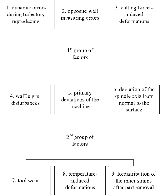
Рис. 2. Факторы, вызывающие отклонения толщины остаточного полотна
Fig. 2. Factors which affect cell bottom thickness errors
It should be noted that, regardless of the physical nature of the deviation (geometric, force, temperature factors), as a rule, the random component is reduced by design and technological methods, and the functional (systematic) component is removed by digital correction [20].
It must be emphasized that the final value of the residual web thickness is determined on the finishing pass. The finishing pass provides the specified surface finish and a significant reduction in cutting forces. In this case, the influence of the random component of cutting forces on the thickness of the residual blade is significantly reduced.
Factors that strongly affect the thickness of the residual афикшс and currently underexplored. The factors in final milling of a pocket are:
-
1) deviation of the spindle axis from the normal to the machined surface;
-
2) errors of copying the back wall of the pocket.
Influence of deviation of the spindle axis from the normal to the machined surface on the deviation of the thickness of the residual web.
Figure 3 shows a diagram of the formation of an error in the thickness of the residual web due to the deviation of the spindle axis from the normal to the surface. As can be seen in the figure, the position of the tool is corrected at point A 0 on the central axis of the tool according to the signal V from the contour tracking sensor, which is located coaxially with the cutter.
The shaping of the bottom of the pocket is carried out at points A1 1 or A 2 , depending on the angle of inclination ∠ α of the surface line of the rear wall of the workpiece to the end of the tool. As a result, an error E occurs in the thickness of the residual fabric. If we consider the area of the surface of the rear wall of the workpiece as a straight line in the vicinity of the point A 0 , then this error can be expressed by the formula
E =
R фр *360
--tg a n D
here R c – cutter radius; D – workpiece diameter.
tg a =
V i + i - V - i B i + 1 - B i - 1
here V i – circuit tracking sensor readings in point i ; В i – table rotation sensor readings in point i .
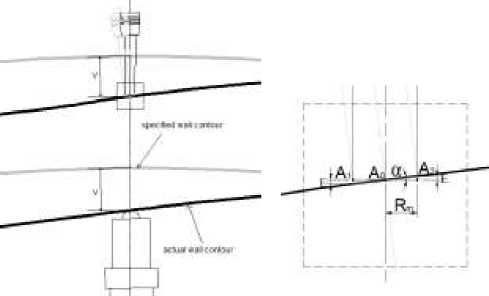
Рис. 3. Схема образования ошибки по толщине остаточного полотна из-за отклонения оси шпинделя от нормали к поверхности
Fig. 3. Schematics of the generation of the cell bottom thickness error due to deviation of the spindle axis from the normal to the surface
Using the signal V from the contour tracking sensor, obtained during the preliminary measurement of the workpiece, we divide it into sections and approximate the signal using the least squares method V = k * B + t in each of the sections:
n * i:, By, - x:, Bi * x:, Vi n * X ”=, Bi - (Zi, B^
£ny - k * B
^_ i=1 I=1 1 ________ ^^ I=1 i
n
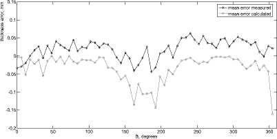
Рис. 4. Кривые усредненных ошибок по толщине остаточного полотна для всего пояса карманов
Fig. 4. Curves of the mean values of the cell bottom thickness errors for the whole row of cells
here V i – readings from the circuit tracking sensor in point i ; B i – table rotation sensor readings in point i ; n – number of points of the approximating line.
Further, according to formulas (1) and (2), the error values in each of the sections are calculated. Figure 4 shows the error curves for the thickness of the residual fabric: the black curve is the average values of the measured errors, the gray curve is the calculated errors in accordance with (1) and (2). From fig. 4 it can be seen that the calculated deviations correlate well with the measured deviations of the processing of the pocket belt.
Influence of copying error of the back wall of the pocket on the deviation of the thickness of the residual fabric. The effect of copying error of the rear wall of the workpiece on the thickness of the residual fabric is illustrated in Fig. 5. Here: 1 - gray solid line - signal V from the contour tracking sensor, recorded during the rotation of the turntable with the workpiece along the B coordinate in the forward and backward directions, 2 - black solid line - the signal obtained by "mirror reflection around the vertical axis" signal V, recorded during the preliminary measurement of the rear wall of the cell without reversing, that is the “ideal” signal from the copy sensor; 3 – black dashed line – B axis rotary table encoder signal; 4 – gray dashed line – Z-axis encoder signal (vertical movement of the caliper). As can be seen from Fig. 5, there is a significant difference between the "ideal" signal V - curve 2 and the signal V - curve 1, recorded by the copy sensor during the rotation of the turntable with the reverse along the coordinate B. A characteristic "shelf" is observed, namely at the moment of reverse [21].
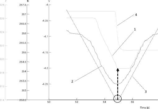
Рис. 5. Сигналы с датчика копирования задней стенки при изменении направления движения
Fig.5. Signals from the opposite wall tracking sensor during the abrupt changes in the movement direction
A possible reason for the discrepancy between the signals is the presence of an "elastic" gap in the copying system "copied surface - measuring tip - converter" displacement - electrical signal "- tracking drive. To test this assumption, a model of a wafer processing copier system was built in Simulink in accordance with the scheme shown in Fig. 1.
The model includes a contour tracking sensor (V model block in Fig. 6) with a Backlash gap and a drive model along the W coordinate (W model block), which processes the signal from the tracking sensor. To model the gap, a standard Backlash block was used, which is usually used to model a geometric gap [21]. In this model, the “ideal” signal V is formed from an array of data obtained by preliminary measurement similar to curve 2 (Fig. 5). The signal is fed to the input of the tracking system model - the V_model block with the Backlash gap block and is output to Scope1, where it is compared with the vmeas signal measured during the finishing of the cell along the zigzag trajectory. After that, this signal is fed to the input of the drive model, block W_model; the output signal is used to calculate the estimated error E_calculated as the difference between the pre-measured signal V and the actual signal W at the output of the clearance system. The calculated error along with the measured error E_measured is output to Scope2.
On Fig. 7 shows the signals from Scope1 when simulating a passage through one cell. Here 1 is a gray dashed line - the actual measured copy signal V during processing, 2 - a black solid line - the calculated "ideal" signal from the contour tracking sensor (calculated based on data on the pocket curvature before processing), 3 - solid gray line - signal V, obtained by modeling ("elastic" gap) when processing the pocket along the "zigzag" trajectory.
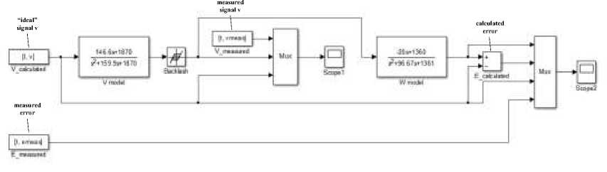
Рис. 6. Модель копировальной системы вафельной обработки при наличии нелинейности типа «зазор» в измерительной цепи слежения за контуром задней стенки заготовки
-
Fig. 6. Model of the waffle grid mirror milling system in the presence of nonlinearity of “backlash” type in the measuring circuit of the opposite wall tracking system
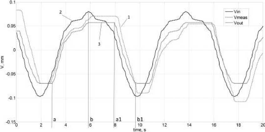
Рис. 7. Сигналы, полученные на Scope1 при моделировании прохода по одной ячейке
-
Fig. 7. Signals received in the Scope1 during modeling of the pass through one cell
The nature of all three curves in the section ab and a 1 b 1 is identical, and in the section ba 1 significant differences are observed, namely, the characteristic “shelf” is a sign of the gap.
Figure 8 shows the signals from Scope2 when modeling the formation of a deviation in the thickness of the residual fabric when passing through one cell. Here 1 is a gray dashed line - the signal W of the tool movement along the spindle axis obtained on the drive model during pocket machining along the zigzag trajectory, 2 - black dashed line - the calculated "ideal" signal from the contour tracking sensor (calculated based on data on the pocket curvature before processing), 3 - black solid line -measured error in the thickness of the residual web, 4 - gray solid line - calculated error in the thickness of the residual web. The calculated curve 4 is the “difference” of curves 1 and 2 and, in general, are in good agreement with curve 3 , with the exception of segment ab (perhaps due to inaccurate matching of points counting of measurement and simulation signals).
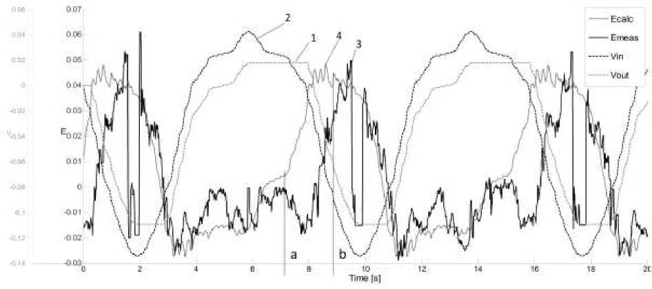
Рис. 8. Сигналы, полученные на Scope2 при моделировании прохода по одной ячейке
Fig. 8. Signals received in the Scope2 during modeling of the pass through one cell
The simulation results show that the periodic error with a sharp change in the trajectory (reversal of one of the controlled coordinates) is functional in nature and can be explained by an "elastic" gap in the copying system of the back wall of the workpiece. It should be noted that it is difficult to compensate for this error by disturbance correction methods, especially for more complex trajectories of the “spiral” type.
The results obtained and presented above of modeling the influence of individual factors on the thickness of the residual fabric indicate the fact that among the factors under consideration (Fig. 2) it is not possible to single out 1–2 factors that would dominate in terms of the degree of influence on the integral deviation of the thickness of the residual fabric, and this is the basic prerequisite for choosing the most suitable method to improve the processing accuracy in terms of the thickness of the residual fabric. Below, the main methods for improving the accuracy of machining are considered on an enlarged basis and the choice of a correction system and algorithm is substantiated.
Methods for improving the accuracy of processing by the thickness of the residual fabric
In [22], the main directions for improving the accuracy of metal-cutting CNC machines divided into two groups are considered:
-
1) improvement of design of equipment and manufacturing technology;
-
2) improvement of the control process of the CNC machine by methods of software correction.
As mentioned above, in relation to the finishing milling of a waffle background, it seems promising to use software correction methods, since they allow compensating the most significant functional components of the error in processing the residual web.
There are the following correction methods used in the process of CNC machine control:
-
1) correction methods based on a priori information (correction based on the results of machine calibration, UE pre-emphasis);
-
2) correction methods based on the feedback principle;
-
3) correction methods based on the principle of disturbance compensation.
At the same time, the results of additional control and measurement operations can serve as input data for correction methods:
-
- signals from encoders of axes X ( t ), Y ( t ), Z ( t ), B ( t ),..;
-
- signal from the tracking sensor for the contour of the rear wall V(t);
-
- a signal from an ultrasonic sensor for controlling the thickness of the residual web T(t), etc.
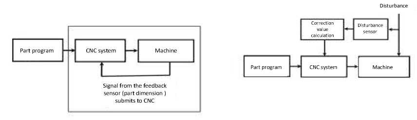
The greatest effect in terms of compensation for the influence of most factors can be obtained by using the main control principle - control by deviation in the system with negative feedback, namely, the system of ultrasonic measurement (ultrasound) of the thickness in the active control system with feedback on the thickness of the residual web (Fig. 9, a).
б
Рис. 9. Основные системы коррекции: а – по обратной связи; б – по возмущению
Fig. 9. Generalized schematics of the correction system: a – with feedback correction; b – with disturbance correction
The ultrasonic sensor is installed in such a way that it measures the thickness of the residual web on the shell being processed directly in the cutting zone. Information about size deviations enters the CNC system, as a result of which the trajectory of the cutter relative to the workpiece is corrected in real time (Fig. 9, a):
Yc (t) = Yef (t) + ( Tact (t)- Trf ) ' Wper ( S ) .
Here Y c ( t ) – the current value of the feedback correction signal for the thickness of the residual fabric to drive the Y axis ; Y ref ( t ) – is the given current program value of the Y coordinate; T act ( t ) – the current measured value of the residual fabric thickness; T ref – the specified program value of the thickness of the residual fabric; W per ( s ) – the transfer function of the controller that calculates the corrective action along the Y coordinate based on the readings of the feedback sensor for the thickness of the residual web. However, at present, this solution cannot be implemented due to the large delay of the signal entering the CNC system from the USI system (delay time ≥ 442 ms) [23; 24].
In accordance with the theory of automatic control, an alternative to the principle of control by deviation is the principle of control by perturbation (Fig. 9, b), which gives good results in cases where one or two strongly acting factors act on the controlled object and the laws of influence are well studied perturbations on the controlled process. Data from the tracking sensor for the contour of the rear wall of the workpiece V(t) in relation to data from the encoders of the B(t), Z(t) axes can be used in the disturbance correction system (Fig. 9, b) to calculate the correction K dist , based on the above scheme for the influence of the deviation of the spindle axis from the normal to the surface. In this case, the current value of the disturbance correction signal for the Y -axis drive will be determined by the expression:
Y c 1 p + K dist ,
here Y c – specified movement along the Y coordinate, taking into account the correction for disturbance; Y p – specified movement in Y on the uncorrected NC; K dist = f ( B , Z , V , R фр ) – correction calculated by (1), (2) for the current values of the coordinates (B, Z).
Without a significant loss of accuracy, the correction Kdist can be calculated in advance before finishing milling. In this case, an array of values [ B v , Z v , V ], obtained by preliminary measurement of the rear wall of the workpiece with a sensor V along the entire belt of pockets, is used.
This array [ B v , Z v , V ] is loaded into the disturbance correction block, as a result, an array of corrections [ B v , Z v , K ] is calculated for all pairs of values ( B v , Z v ). Then the disturbance correction block calculates a correction for the reference points of the trajectory [ B p Z p Y p …] by interpolating the previously calculated correctors.
Regardless of whether the correction signal is calculated before or during processing, this approach allows to compensate for the influence of one factor out of nine, which is insufficient to achieve the invariance of the controlled coordinate from disturbances.
Therefore, it is proposed to improve the existing technology for processing the wafer background by applying a combined correction system (self-adjusting system plus perturbation control).
Combined correction system
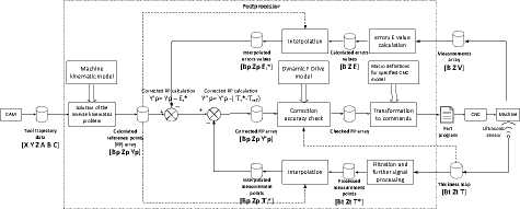
On Fig. 10 a block diagram of a combined correction system that uses both disturbance correction and feedback correction is shown.
This system uses several streams of information:
-
– the results of measuring the thickness of the residual fabric by the ultrasonic testing system after finishing the i pocket in the form of a thickness map [ Bi t Zi t Ti act ];
-
– the results of measuring the rear wall of the workpiece by the contour tracking sensor V in the form of an array [ B v Z v V ];
-
– array of reference points of the machining path [ B p Z p Y p …], calculated in the postprocessor based on the tool path and cutting conditions specified in the CAM system taking into account the kinematic model of the machine.
УП
Рис. 10. Блок-схема комбинированной системы коррекции с самонастройкой
Fig. 10. Block diagram of the combined correction system with self-tuning
Finishing of the first cell is divided into two passes: semi-finishing with an allowance b for finishing Y 1 p = Y p + b and finishing according to the adjusted NC Y 1 p = Y 1 c . After the semi-finishing pass, the thickness map [ Bi t Zi t Ti act ] and the array of reference points of the trajectory of the uncorrected NC [ B p Z p Y p … ] are loaded into the self-tuning block, where the initial processing of the thickness signal (smoothing, filtering), signal interpolation takes place. As a result, the feedback correction signal K 1 fb is calculated for all reference points of the UE trajectory:
K 1b = T Pf
—
T ref — Ь ,
here T 1 pf – the results of measuring the thickness of the residual fabric of the first cell after a semifinishing pass at Y p = Y p + b ; T ref – specified thickness of the residual fabric; b – allowance for semifinishing.
The corrected NC program for moving along the Y axis, which executes the compensation signal during finishing, will be
Y c1 = Y p + K 1b .
When finishing the second, …, i -й, i +1 cell, the same NC is applied as for finishing the first cell
Y c = Y p + K2 b = Y p + K 1b
Y c = Y p + K f, = Y p + K b
Vi+1 —V -L i,1+1 —V _i_ ^i
Yc = Yp + Kfb = Yp + Kb here Yic – movement specified in the block along the Y coordinate when finishing the i-th cell taking into account feedback correction; Yp – movement along Y specified in the frame along the uncorrected NC; Kifb – feedback correction signal for i cell.
In this case, the influence of factors of group II, considered earlier, will lead to an increase in Ti act errors when processing subsequent cells. Therefore, it is necessary to periodically recalculate (reconfigure the system) the Ki f b feedback correction signal to ensure the required finishing accuracy. To this end, during the finishing of the i cell, the thickness map [ Bi t Zi t Ti act ] is measured, the thickness measurement results are loaded into the self-tuning block, where the thickness signal Tiact is evaluated for belonging to the boundary range ( T th min … T th max ). If the value of the thickness of the residual fabric T i act after processing the i cell goes beyond the signal boundaries, the correction signal for the next cell Ki +1 fb is recalculated in the same way as it was done for the first cell, i.e., a semi-finishing pass is performed with an allowance b for i + 1 cell, calculation of correctors Ki +1 fb . Next, the cells i+1, i+2 , etc. are finished with the calculated corrector Ki+1 fb . The above can be described by the formula:
K f = K f , at maxC ) < Th* mT ) > T ^
Kb1 = / + - Tref - b, at maxTc) > TT ,min(T,c) < TT , here Ki+1fb – feedback correction signal for i+1 cell; T iact –the results of measuring the thickness of the residual fabric of the i cell after the finishing pass according to the program Yic; T i+1pf – the results of measuring the thickness of the residual fabric i+1 cells after a semi-finishing pass according to the program Yp = Yp + b; Tref – specified residual web thickness; b – allowance for semi-finishing work; Tthmin, Tthmax – the maximum and minimum signal value of the thickness of the residual fabric.
It is possible to increase the interval between system reconfiguration operations by compensating for the influence of part of the group II factors by introducing and calculating an additional correction for the Ki dist disturbance. As described above, this Ki dist corrector can be calculated before finishing using formulas (1) and (2) based on the array of values [ B v Z v V ] obtained by preliminary measurement of the back wall of the workpiece, and the array of reference points of the machining path of i cell [ B p Z p Y p … ].
Taking into account the disturbance correction calculated before processing and the feedback correction calculated during processing, formula (6) for finishing the i cell will be
Y c = Y p + K b + K dst , (11)
here Ki dist –disturbance corrector calculated by formulas (1) and (2).
Conclusion
The following conclusions can be drawn:
-
– the factors were combined into two groups, leading to deviations in the thickness of the residual shell fabric, on the basis of dependence in the function of the processing point number inside one cell and in the function of the pocket number inside the row and on the row number;
-
- the influence of the deviation of the spindle axis from perpendicularity to the surface to be machined on the thickness of the residual fabric was studied and a method for calculating and introducing a corrective amendment to the NC was developed;
-
– the effect of the error of copying the back wall of the pocket on the deviation of the thickness of the residual fabric was studied and the mechanism (“elastic” gap) of the formation of a specific shape (the presence of a “platform”) of the deviation curve of the residual web during the reverse of the turntable was revealed for the case of processing the pocket with stitches. The results of the study can be used to improve the copying mechanism in order to increase the accuracy of processing the residual fabric;
-
– a combined correction system that combines pocket-to-pocket self-tuning with pass-to-pass selftuning and disturbance control is proposed;
-
– a scheme and algorithm for the operation of a combined correction system with self-tuning from pocket to pocket was developed as the most rational (number of corrections) in terms of reducing the functional component of the error in the thickness of the residual web;
-
- the material presented in the article on the study of the possibilities of improving the accuracy of processing the residual fabric of wafer shells by the methods of software correction as a whole makes it possible for engineers - designers of special equipment to compare the possibilities of digital correction and design and technological directions for improving technological equipment;
-
- to complete the ongoing research on the accuracy of processing the residual fabric, it is necessary to test the proposed algorithm by simulation based on the available measurement data for the deviations of the machined shells on the HPPS machine.
References Research of the ways to increase the accuracy of the mirror milling machining of the waffle grids by means of the digital correction techniques
- Kac I. L. K istorii sozdaniya konstrukcii, metoda raschyota i primerov realizacii vafel’nyh obechaek bakov raket [To the history of the creation of design, calculation techniques and examples of implementation of the waffle shells of the rocket tanks] (In Russ.). Available at: https://listak.livejournal.com/2484.html (accessed: 22.12.2021).
- Vorozhejkin V. A, Litvinchuk A. Ju [Pass-through method of the manufacturing of the loadcarrying bodies of the products of space industry]. Reshetnevskie chtenija: materialy XXI Mezhdunar. nauch. konf. [Materials XXI Intern. Scientific. Conf “Reshetnev reading”]. Krasnoyarsk, 2017, p. 481–482 (In Russ.).
- Zajcev A. M. Razrabotka napravleniy povysheniya ehffektivnosti tekhnologicheskoy podgotovki proizvodstva detaley i uzlov raketno-kosmicheskoy tekhniki [Development of the approaches of increasing the efficiency of the engineering process of the parts and units of the space industry. Dr. techn. sci. diss]. Moscow, BMSTU Publ., 2016, 166 p.
- Zajcev A. M., Shachnev S. Yu. [Determination of the manufacturability of the shells with waffle-based design]. RITM mashinostroeniya. 2018, No. 4, P. 42–43 (In Russ.).
- Pas O., Serkov N. Developing an algorithm to control the accuracy of the milling of aerospace parts with cellular structure by using copying machine-tools with CNC of “SVO” type. IOP Conf. Series: Materials Science and Engineering. 2019, Vol. 489, P. 351–355.
- Pas’ O. V., Serkov N. A. [An improvement of the accuracy of the mirror-milling of the shells with cellular structure by means of self-tuning approach pass by pass]. XXXII Mezhdunarodnaja innovacionnaja konferencija molodyh uchenyh i studentov po problemam mashinovedenija. Sbornik trudov konferencii [Materials XXXII International Scientific Conference of Young Scientists and Students on problems of Mechanical Engineering]. Moscow, 2021, P. 498–502 (In Russ.).
- Del Sol I., Rivero A., López de Lacalle L.N., Gamez, A.J. Thin-Wall Machining of Light Alloys: A Review of Models and Industrial Approaches. Materials (Basel), 2019, Vol. 12, P. 2012.
- Liu S., Xiao-dong S., Xiao-bo G., Wang D. Simulation of the deformation caused by the machining cutting force on thin-walled deep cavity parts. The International Journal of Advanced Manufacturing Technology. 2017, Vol. 92, P. 3503–3517.
- Du Z., Zhang D., Hou H., Liang S.Y. Peripheral milling force induced error compensation using analytical force model and APDL deformation calculation. The International Journal of Advanced Manufacturing Technology. 2017, Vol. 88, P. 3405–3417.
- Li Z.-L., Tuysuz O., Zhu L.-M., Altintas Y. Surface form error prediction in five-axis flank milling of thin-walled parts. International Journal of Machine Tools and Manufacture. 2018, Vol. 128, P. 21–32.
- Bi Q., Huang N., Shaokun Z., Shuai C., Yuhan W. Adaptive machining for curved contour on deformed large skin based on on-machine measurement and isometric mapping. International Journal of Machine Tools and Manufacture. 2018, Vol. 136.
- Wang X., Li Z., Bi Q., Zhu L., Ding H.. An accelerated convergence approach for real-time deformation compensation in large thin-walled parts machining. International Journal of Machine Tools and Manufacture. 2019, Vol. 142, P. 98–106.
- Huang N., Yin C., Liang L., Hu J., Wu S. Error compensation for machining of large thinwalled part with sculptured surface based on on-machine measurement. The International Journal of Advanced Manufacturing Technology. 2018, Vol. 96, P. 4345–4352.
- Bi Q., Wang X., Wu Q., Zhu L., Ding H. Fv-SVM-Based Wall-Thickness Error Decomposition for Adaptive Machining of Large Skin Parts // IEEE Transactions on Industrial Informatics. 2019, Vol. 15, P. 2426–2434.
- Ge G., Du Z., Yang J. On-machine measurement-based compensation for machining of thin web parts. Procedia Manufacturing. 2020, Vol. 48, P. 844–851.
- Panczuk R., Foissac P.-Y. Process and device for machining of panels. US Patent No. 7682112B2, 2010.
- Aviacionnyy konsalting. Oborudovanie i tehnologiya mehanicheskoy obrabotki metodom zerkal’nogo frezerovaniya [Aviation Consulting. Mirror milling machining equipment and technology] (In Russ.). Available at: https://www.aviacons.ru/ru/postavka-importnogo-oborudovaniya/zerkalnoyefrezerovaniye/ (accessed: 22.12.2021).
- Pisarenko A. A., Kovalev A. M. [Machining center SVO-3500 for manufacturing waffle shells for using in large loadcarrying bodies of the products of space industry]. Vestnik FGUP NPO Tekhnomash. 2018, No. 6, P.86–90 (In Russ.).
- Bartrutdinov R. G., Sysoev S. K. [Manufacturing technology for producing waffle grid for aircrafts shells]. Aktual’nye problemy aviacii i kosmonavtiki. 2011, No. 1, P. 7–8 (In Russ.).
- Serkov N. A. [Main ways of increasing the accuracy of the machine-tools]. Problemy mashinostroeniya i avtomatizacii. 2010, No. 2, P. 26–35 (In Russ.).
- Pas O., Serkov N. Influence of the gap and the friction on trajectory reproduction accuracy in a multiaxis machine with cnc. JVE International Ltd. Vibroengineering PROCEDIA. 2016, Vol. 8, P. 483–488.
- Serkov N. A. Tochnost’ mnogokoordinatnyh mashin s ChPU: Teoreticheskie i yeksperimental’nye osnovy [Accuracy of the multiaxis machine tools: theoretical and practical basics. Dr. techn. sc. diss]. Moscow, Lenand Publ., 2015, 304 p. (In Russ.).
- Zhang S., Bi Q., Ji Y., Wang Y. Real-Time Thickness Compensation in Mirror Milling Based on Modified Smith Predictor and Disturbance Observer. International Journal of Machine Tools and Manufacture. 2019, Vol. 144, P. 1–14.
- Mahmud A. Mechanical Pocket Milling of Thin Aluminum Panel with a Grasping and Machining End Effector. Universite De Montreal, 2015, 147 p.
