Research on Spacecraft Illumination

Author: Bo Cai, Ling Li, Jing Hu, Biao He, Yuan Long, Dengyi Zhang
Journal: International Journal of Modern Education and Computer Science (IJMECS) @ijmecs
Article in issue: 4 vol.3, 2011.
Free access
Illumination analysis of spacecraft is very important. This paper firstly introduces the importance of spacecraft illumination analysis in aerospace fields and points out that illumination conditions will influence the design of shape of spacecraft body and the installation of spacecraft equipments. Then, it discusses two methods for analyzing spacecraft solar-panel shadow and illumination conditions: ray tracing illumination algorithm and polyhedral mesh contour edge projection algorithm and compares their efficiency and feasibility. Shadow area and solar area are computed of every cell on solar panels. We designed solar panel single-axis rotation experiment to validate the proposed algorithm. The experimental results show that contour edge projection algorithm has fine accuracy and costs less time. For detailed illumination information, we apply a practical segment clipping algorithm after some comparisons.
Ray tracing, contour edge projection, Single-axis rotation, Multi-axis rotation, shadow area, Line Segment Clipping Algorithm
Short address: https://sciup.org/15010245
IDR: 15010245
Text of the scientific article Research on Spacecraft Illumination
Published Online July 2011 in MECS
Illumination analysis of spacecraft means analyzing the sunlight-receiving situation of spacecraft body and solar panels, which includes solar incidence angle analysis on spacecraft body surfaces and solar panels, analysis of shadow area on panels and illumination factor. It is very meaningful for the design of spacecraft. Firstly, increasing panel illumination area will be benefit for solar cell, supplementing the energy needed by satellite, a kind of spacecraft, working and operation [1]. Secondly, analysis of illumination conditions of spacecraft body has significance for the body shape design and installation of spacecraft equipments. It is suitable for the light perception apparatus to be fixed on illumination surfaces of spacecraft; as for the equipments working at low temperature, they should be installed in the spacecraft's backlight surface.
Ref. [2] tells us that shadow recognition on spacecrafts also takes on some special significance. On the one hand, shadows on the images cause some loss of information, and consequently they make image-analysis processes more difficult or even fail. On the other hand, we may utilize the shape and position of the cast shadow as a valuable cue for inferring 3D scene information, for example, for delineation and height estimation and so forth. Then, satellite images could be corrected and 3D information can be inferred.
Various related illumination analysis algorithm have been done in literatures in recent years. However, there is relatively little research on spacecraft illumination. Ray tracing and light projection method in computer graphics can be applied to the study of spacecraft illumination. In Ref. [3], Rong Ye and Yong Hu have analyzed sunlight conditions of space remote sensor using global illumination radiosity method and ray tracing method. In Ref. [4], Chanjuan Chen and Baosheng Kang et al proposed a new ray tracing acceleration algorithm based on bounding box method. In Ref. [5], Wenxi Wang and Shide Xiao et al proposed accelerated algorithm for ray tracing based on octree. In Ref. [6], Jing Li and Wencheng Wang raised mesh optimal division for speeding up ray tracing computation. These researches, discussed later, provide reference for the study of spacecraft illumination.
This paper mainly researches on spacecraft illumination algorithm and segment line clipping algorithm for solar cell illumination information. Two panel illumination algorithms are given: panel shadow area computing algorithm based on ray tracing method and polyhedral mesh contour edge projection algorithm. These two algorithms have been implemented in experiment and polyhedral mesh contour edge projection algorithm is applied in practical project. They analyze panel shadow area applied to single-axis rotation and multi-axis rotation. Whether single-axis rotation or multiaxis rotation, it needs to keep greatest exposure of solar panels to sunlight [7]. The experimental results show that contour edge projection algorithm has fine accuracy and is more practical.
Segment Clipping Algorithm mainly depends on calculation of intersection points of two line segments. There are some differences from intersection points of two lines. We need to do more judgments. Firstly, algorithms of spacecraft illumination are discussed.
-
II. Model Definition
-
A. Sun-Earth Coordinate Model
Sun - Earth's coordinate system is defined as the geocenter of the earth for the coordinate origin and the Sun making circular motion around the earth. Light direction is the vector connecting the sun and the earth, while position of sun is got through the calculation of true sun apparent motion. Given a specific time t0 (including year, month, day, hour, minute and second) with the hour of th , we can determine ascension-
( α , δ ) declination coordinates m 0 m 0 and latitude-longitude
( λ , ϕ )
coordinates m0m0 of mean sun at the equator as given in (1) and (2):
λ m 0 = 120 o + 15(12 - t h ), ϕ m 0 = 0 (1)
α m 0 = λ m 0 + 15( t h - 20), δ m 0 = 0 (2)
Then, compute ascension-declination coordinates ( α , δ ) of true sun. In the geocentric coordinate system, the ascension difference is equal to the longitude difference; declination difference is equal to latitude difference. Therefore, we can acquire the latitude and longitude ( λ t , φ t ) of the true sun at any time by (3) and (4).
λ t = λ m +ΔΩ , φ t =Δ δ (3)
α t = α s +ΔΩ , δ t =Δ δ (4)
Finally, translate the latitude and longitude into threedimensional (3D) coordinate, which is the position of sun in this coordinate.
-
B. Spacecraft Model
Spacecraft model, a satellite or a detector, discussed in this paper is designed as follows: Body is a convex polyhedron and solar panel is a plane. A spacecraft is represented by a polyhedral mesh. Mesh consists of multiple neighboring triangles [8]. It stores information of vertices, indices and planes in it. Every spacecraft has a running orbit. For a specific type orbit, when classic orbit element designed and launch time is given, we can calculate position of spacecraft at every moment.
-
III. Contour Edge projection algorithm
-
A. Computation of Solar panel’s shadow based on ray tracing
Analyzing illumination of solar panel based on ray tracing needs get intersection of sunrays and polyhedral mesh of spacecraft body, which can be arbitrary shape of convex polyhedron. The solar panel is divided into M * N small pieces (actually rectangles). Ray starts at the position of sun and ends at the middle point of each rectangle. Sunray intersecting spacecraft body means panel has been obscured by body and it will cast a shadow on panel. Illumination factor
( Ir ) can be worked out by counting intersect numbers ( Internum ) of rays. Then we can get the shadow area ( Sa ) and illumination area ( I a ) by panel area ( Pa ) as given in (5), (6) and (7):
Sa = Pa * Internum /(M *N )
I =P-S(6)
a aa
Ir = 1 - Internum /(M *N )
Final result
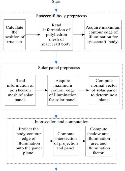
Figure 1. Flow chart of acquiring contour edge and intersection algorithm illumination. It can greatly accelerate because only polygon projection and crossing are needed.
-
B. Contour edge projection algorithm
The algorithm is designed as follows: Obtaining vertex information of spacecraft body, we can get outer contour edge of it according to direction of sunlight. Then project outer contour edge onto the panel along the direction of sunlight. Cross projection polygon with panel polygon, the intersection of these two polygons is shadow region. As computing and intersection in 3D space are prone to error, the method of projecting 3D space into twodimensional (2D) space is selected (discussed later in Algorithm Steps). Finally, the section in 2D space is back-projected into 3D space. Algorithm flow is illustrated in Fig.1.
-
C. Algorithm Steps
Step 1 Calculating the position of true sun ( sunPos ) in sun-earth coordinate model to get sunlight vector ( sunLine ). If position of earth is earthPos ,we have:
sunLine = sunPos - earthPos
Step 2 Get vertex and index information through polyhedron grid pointer of spacecraft body and its realtime location, direction and scale factor.
Step 3 Get the maximum outer contour edges of body under the sun and sort contour edges into a closed region ( ContEdge ).
Process of getting maximum outer contour edge of illumination is as follows:
Step 3.1 Traverse surfaces of polyhedral mesh of spacecraft body and compute vertices coordinate of each surface.
Step 3.2 Compute the dot product ( dotPro ) of sunLine and the normal vector ( normal ) of each surface.
Step 3.3 If dotPro is larger than zero, angle between normal and sunray is less than 90 ° .This surface is backlight. On the contrary, the surface can get illumination.
Step 3.4 Add edges of the illumination surface into an edge list ( edgeList ).
Step 3.5 Remove the same edge from edgeList then you can get the final contour edge of illumination.
Step 4 Traverse spacecraft solar panels one by one. Repeat step2 and step3 using polyhedral mesh of solar panel.
Step 5 Compute projection region ( CP ) of ContEdge onto panel plane (as an infinite plane) along the direction of sunlight.
Step 6 Judge and calculate intersection of CP and finite panel polygons ( PP ), that is the shadow region.
Process of space polygon intersection is as follows: Step 6.1 Determine projection plane. Calculate the angle between normal and each coordinate axis. If angle between normal and X-axis is less than 80 ° , project CP and PP onto YOZ coordinate plane. If angle between normal and Y-axis is less than 80 ° , project CP and PP onto XOZ coordinate plane. If angle between normal and Z-axis is less than 80 ° , project CP and PP onto XOZ coordinate plane.
Step 6.2 After choosing a coordinate plane as the projection plane, save the angle between normal and the coordinate axis as m _ Rad . Suppose 2D projection of CP and PP are respectively Pro 2 V and Panel 2 V . They store points of 2D space.
Step 6.3 Traverse each edge of CPro and Panel 2 V in 2D plane one by one.
Compute their intersection points successively and save the points in a 2D container named m _ Inter 2 V (2D polygon of intersection region).
Step 6.4 Traverse the vertices of Pro 2 V in turn and determine whether they are within Panel 2 V .If so, record them in m _ Inter 2 V . Similarly, the vertices of Panel 2 V within Pro 2 V are also included.
Step 6.5 Sort the vertices of polygon m_ Inter2V and save the results in it.
Step 6.6 Convert 2D points into 3D points.
Create rays in 3D: Starting point is each vertex of m _ Inter 2 V with a direction of normal vector of the projection plane. Get intersection of rays with finite panel plane, the region enclosed by intersection points shall be the shadow region.
-
D. Algorithm analysis
This algorithm can analyze illumination conditions of spacecraft with arbitrary shape of convex polyhedron and variable
S area( a factor( r
number panels and compute precise shadow ),illumination area ( a )and illumination
).One solar panel is represented by a polyhedral
P mesh of a finite plane. So area of panel ( a ) is length multiplied by width of the finite plane.
Calculation of the shadow area needs to go through a conversion. Firstly, calculate the area of 2D polygon-m_ Inter2V. Then we will get Sa through dividing area mRad above by cosine ( ) .The computation of
-
a and r is the same as ray tracing algorithm.
Several issues should be paid attention to in the algorithm:
-
• When spacecraft is in non-sunlight district, no panels of spacecraft will receive sunshine because the Earth obscures spacecraft. In this situation, only one judge is needed according to the location of the three and set shadow area for panel area to reduce the computational load.
-
• For spacecraft in the sunlight district, calculation of area can also be simplified. The panel obscured by spacecraft body would cast a shadow, but the ones have not been obscured will not. The whole panel is subject to sunlight and illumination area equals to panel area.
iv. Comparison of Algorithms
These two algorithms can accurately calculate illumination characteristic data of spacecraft including shadow area, illumination area and illumination factor and so on. However, there are differences of their speed and performance. The following Table I shows the similarities and differences between them.
The following comparative analysis shows that Contour edge projection algorithm is more feasible than the other algorithm. Therefore, we apply it to analyze spacecraft illumination situation. It can meet the accuracy and speed requirements and provide accurate data analysis.
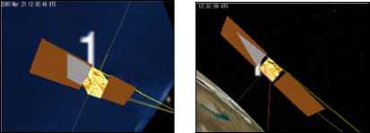
TABLE I. similarities and differences between the two ALGORITHMS
|
Two algorithms |
||
|
Algorithm1 — Ray tracing algorithm |
Algorithm2 — Contour edge projection algorithm |
|
|
Experimental results |
Accurately calculate Р V I J Pa , Sa , a and Ir |
P Accurately calculate a , Sa , a and r |
|
Algorithm speed |
Slow. Because the panels are divided into many pieces, intersection is called many times and more time-consuming. |
Faster. Computation is run only when shadow occurs after judging according to the conditions and streamlines the calculation of other cases. |
|
Feasibility |
Almost feasible. |
Feasible. |
|
Advantage |
Algorithm is simple. It is easy to calculate area and applicable to various shapes of spacecraft. |
High speed, avoid unnecessary work; greater flexibility, suitable for spacecrafts with body of various shapes and panel undetermined number. |
|
Disadvantage |
Slower rate, more computer resources. |
More complex. |
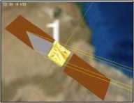
Figure 2. 3D simulation results of real-time rendering
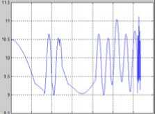
Figure.3.1 2D curve of shadow area
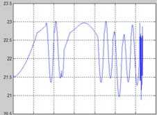
Figure.3.2 2D curve of illumination area
v. Experiments
To verify the algorithm, we design single-axis rotation of solar panel algorithm in Visual Studio C++ 2008 environment. In 3D scene, based on the sun and the earth simulation, satellite running and shadows on panels are simulated.
Initially, determine an original angle of panels according to the projection of sunlight in the orbital plane to keep it nearly vertical to sunlight. In the simulation process, adjust the real-time rotation angle of panels to maintain a certain angle to the sunlight and to meet the most exposure of panels to the sun. Set simulation step as 60 seconds. We call this method to analyze illumination conditions of satellite at each simulation step. It can simulate well for more than one satellite. The realtime simulation results are shown in Fig.2.The upper left corner shows the simulation time. We can see gray shadow of the satellite and yellow lines paralleling to the direction of sunlight.
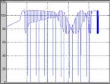
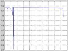
Fig.3.3 2D curve of sun-body
incidence angle
Fig.3.4 2D curve of sun-panel incidence angle
Figure 3. 2D curves
Meanwhile, in order to observe satellite’s illumination situation more directly, we drew 2D curves for shadow area, illumination area, sun-body incidence angle (angle between sunlight and one of satellite body surfaces) and sun-panel incidence angle (angle between sunlight and solar panel). In the selection of suitable simulation step, the curve of shadow area is relatively smooth except full shadow of non-sunlight district. The situation of illumination area is much the same as shadow area. Fig.3 (above) shows the experimental results.
vi. Detailed computation
-
A. Proposition of Algorithm
In some cases, such as analyzing lunar exploration, we need to acquire more detailed illumination conditions. Shadow area and its proportion of the total area are computed of every battery on solar panels.
Algorithm ideas: traverse every small cell (actually a quadrangle) and do clipping operation on every side of the shadow area to the cell. We will get a polygon region or nothing. At last, judge whether the result polygon is shadow area or solar area.
Assume that the solar array has MM lines and NN columns. Each vertex coordinate can be computed out when we know the coordinates of four vertices of the solar panel. In Chapter III, we have shadow area stored in 2D vector m _ Inter 2 V . Vertex coordinate of every side can easily be got. So now the difficulty is which Line Segment Clipping Algorithm is more suitable and how to do clipping of line segment and polygon.
-
B. Algorithm Steps
Step 1 Compute vertices coordinate of every small cell ( ClipRegion ).
Step 2 Get vertices coordinates of every side of shadow region to be the clipping line segment.
Step 3 For every cell ClipR [ i ][ j ] (among which variable i ranges from 0 to MM - 1 and j ranges from 0 to NN - 1 ), compute and judge which vertex is in the shadow region and which is out of it. Record the inner vertices in 2D vector m _ vec 2 BatShadow .
Step 4 Traverse every vertex of shadow region. Compute and judge which vertex is in the cell ClipR [ i ][ j ] and which is out of it. Record the inner vertices in 2D vector m _ vec 2 BatShadow .
Step 5 Do clipping on every shadow side to cell. Record intersection points of clipping line segment and clipping polygon in 2D vector m _ vec 2 BatShadow .
Step 6 If less than two points are got, the shadow area of this cell is zero. If there are more than two points, sort the vertices of polygon m _ vec 2 BatShadow [ i ][ j ] and save the results in it.
Step 7 Calculate the area of m _ vec 2 BatShadow [ i ][ j ], we will get the shadow area of this cell.
-
C. Algorithm analysis
This algorithm can acquire more detailed illumination information of spacecraft and compute precise shadow area, illumination area and illumination factor for every cell on solar panel. The area of one cell can be computed by dividing the whole panel area by MM * NN , where the whole area has been computed in Chapter III.
Calculation of the shadow area on real panel needs a conversion. Firstly, calculate the area in 2D space. Then we will get the result through dividing area above by mRad cosine ( ).
We can simplify the algorithm:
-
• When spacecraft is in non-sunlight district, no panels of spacecraft will receive sunshine. So all the cells have full shadow area.
set the shadow area of current cell as full cell area zero.
-
D. Line Segment Clipping Algorithms
There are many clipping algorithms. Firstly, let’s review some of them.
Cohen-Sutherland line clipping algorithm is explained in Ref. [9] and Ref. [10]. This efficient algorithm does simple region checks to see whether a line can be trivially rejected or accepted. For example, in Fig.4, line segment CD can be trivially rejected because x coordinate of both endpoints are smaller than x min . Line segment GH is trivially accepted
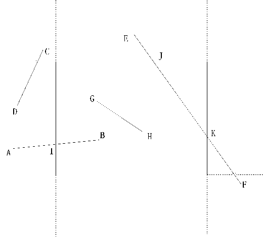
Figure 4. Cohen-Sutherland Clipping
because both endpoints satisfy inequality
x ≤ x≤ x and y ≤ y≤ y .
min max y min y y max .
If a segment cannot be trivially rejected or accepted, it is divided into several segments at a clip edge, so one segment can be trivially accepted. A line may require several “clips”, such as line segment EF . To perform the trivial accept or reject tests, the edges of the clip region are extended, defining nine separate regions in a plane. Each region is labeled by a
4-bit binary number where each bit (1 = true, 0 = false) corresponds to the following conditions:
bit 1: y > ymax above top edge bit 2: y < ymin below bottom edge bit 3: x > xmax right of right edge bit 4: x < xmin left of left edge
If logical AND of out codes of two endpoints is nonzero, then the line segment is trivially rejected, as line segment CD in Fig.4. If a line can not be easily rejected, the endpoint is replaced by the intersection point between line and edge, as line segment AB turned into IB . And intersection point between two line segments is much easy.
Cohen-Sutherland line clipping algorithm applies to a rectangular clipping region. Another 2D rectangle side-by-side clipping algorithm is proposed in Ref. [11]. But sometimes we have non-rectangular polygons to deal with, so we need a more general clipping algorithm.
In Ref. [12], a kind of clipping algorithm is proposed that applies to different clipping regions, containing rectangle, parallelogram and circle. Let’s firstly take rectangular clipping region as an example.
Suppose the line the line segment on does not parallel with coordinates for universality (if parallel, the issue will be much
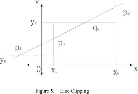
easier) and its equation is y = kx + b (k Ф 0). The line will have four intersection points with the window on its sides or extension lines of edges. Sort abscissas of these four points in ascending or descending order and record their results asx1 , x2 , x3 , x4 . And then sort the middle points x2 ,x3 and jumping-off point and end point of line segment L in the same order. Record abscissas of the two middle points as x'' and x" . Ordinates of the two points y'' and y" can be worked out through formula y = kx + b . Judge the following two formulas to see if they simultaneously satisfy.
-
(I) xL < ( x + x ) / 2 < xR ,
'' "
( П ) У в < ( y + y ) / 2 ^ У т
If true, line segment ppqq will be the visible part of line segment L , as in Fig.5. Here coordinates of pp and qq are separately ( x ', y '') and ( x ", y ") . Otherwise line segment L has no visible part.
This algorithm has comparatively wide application. But considering computation of intersection point wastes much time, we take other clipping algorithms into account.
vii. A Suitable Clipping Algorithm
-
A. Basis of the New Line Clipping Algorithm
Clipping algorithm aiming at convex polygon is explained in Ref. [13]. This algorithm is based on two basic theorems.
-
Theorem 1 The necessary and sufficient condition of line PQ intersecting with line segment AB is that endpoints A and B are not in the same side of line PQ .
-
Theorem 2 There are at most two intersection points of a line segment and a convex polygon.
Both theorems are relatively easy to be proved, so we skip over them hereon.
-
B. Algorithm Thought
In practical use, line segment clipping are executed rather than straight line. So we may consider the line on which the
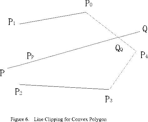
specific line segment is, and do some other operations. Algorithm thought: check every vertex of polygon to determine which side of line PQ it is in. Intersection points are calculated only when two vertices of the side are in different sides of line PQ . And then remove the intersection point on the extension line of the line segment PQ (not the real intersection point of PQ and polygon), as in Fig.6.
Computation of inner normal vectors is not any longer required in this algorithm, which is different from Cyrus-Beck Algorithm, a classical line clipping algorithm introduced in Ref. [9]. Intersection point calculation of line and every polygon side (what we do in algorithm of Ref. [12]) is also not needed; so many calculations are leaved out.
Mark every vertex of convex polygon as Pi ( xi , yi ) (i = 0, 1, •", n-1), and we define P n = P 0 . Assume coordinates of P and Q are respectively P ( m 1, n 1) and Q ( m 2, n 2) , so the equation of the straight line across points P and Q is
ax + by + c = 0
among which, a = n 2 — n 1 , b = m 1 — m 2 ,
c = m 2 n1 — m1 n 2.
Set o as o = ax. + by. + c . Point P , P , will be in i i i i i i + 1
the different sides of line PQ if oo . < 0 , as line i i+1 , segment P0P4 and P1P2 in Fig.6. Specific steps of new algorithm are as follows:
-
(1) Compute operator o i . If o i equals zero, point P 0 is one intersection of line PQ and polygon. Add one to counting number.
-
(2) Compute o i + 1 when variable i ranges from 0 to n — 1 . If o i + 1 equals zero ( o i + 1 = 0 ), point P. + 1 is also an intersection point. Add one to counting number. When count exceeds two, exit the loop.
-
(3) If PP + 1 < 0 , calculate the intersection point of line PQ and PP + 1 . Add one to counting number. When count exceeds two, exit the loop. Otherwise, go back to Step (2).
-
(4) For clipping algorithm, we need to get the visible part and the invisible part of the line. But for engineering requirements, only intersection points are needed.
This algorithm does judgments before calculation, so it saves much time. And number limit of intersection point reduces excess calculation.
viii. Conclusion
Analysis and experimental results show that contour edge projection algorithm has fine accuracy and costs less time than ray tracing algorithm.
In contour edge projection Algorithm, we figure out which surfaces are subject to sun, which are the backlight faces through the computation of angles between body surfaces and the sunlight to help determine the installation of equipments and instruments. To ensure the long working time of spacecraft, we should install spacecraft equipments reasonably and maintain the exposure area of solar array as large as possible.
For further use, illumination conditions on every cell of the solar panel are discussed. When a suitable line clipping algorithm is applied, the computation and discussion become much easier. Maybe better clipping algorithm will appear later on.
References Research on Spacecraft Illumination
- Zhifei Wu and Jinshu Chen, Analysis of satellite power subsystems battery failure of “Tsinghua Space I” (in Chinese), Ninth Annual Space Energy Conf. of Chinese Society of Astronautics, 2005, pp.256-258.
- V.ARE´VALO, J. GONZA´LEZ and G. AMBROSIO, Shadow detection in colour high-resolution satellite images, International Journal of Remote Sensing, Vol. 29, No. 7, 10 April 2008, pp.2-3.
- Rong Ye and Yong Hu, Study of Method for Analyzing and Calculating Solar Illumination on Space Optical Remote Sensor (in Chinese), Shang hai: Academic, Vol. 30, 2009, pp.28-29.
- Chanjuan Chen, Baosheng Kang, and Jun Feng, A new algorithm for accelerating ray tracing based on inner bounding box technology (in Chinese), Vol.40, Xi an, 2010, pp. 429–430.
- Wenxi Wang, Shide Xiao, Wen Meng, and Hong Dong, Ray tracing algorithm based on octree space partition method (in Chinese), Vol. 28, Chengdu, 2008, pp.656–657.
- Jing Li, Wencheng Wang, and Enhua Wu, Optimizing Grid Resolutions for Ray Tracing (in Chinese), Vol.20,Bei Jing, 2008, pp.971–973.
- Songbai Yu, Analysis of solar panel rotation program of two freedom degrees(in Chinese), Eleventh National Space and the Moving Body Control Annual Conf. China,pp.136-137, 2004
- Xiaoping Xu and Zhou Zhou, Application of Polyhedral Mesh in CFD, Vol.27, 2009, pp. 87-88.
- James D.Foley, Andries van Dam, Steven K.Feiner, John F.Hughes, and Richard L.Phillips (Translators: Shihai Dong, Zesheng Tang, Hua Li, Enhua Wu, and et al), Introduction to Computer Graphics(Chinese edition), Machine Press, May 2005, pp.72-78.
- No author listed, raster_clip, pp.4-10.
- Bin Liu, Yong Wang, and Shuhuai Huang, Research on Two-dimensional Rectangular Window Side-by-Side Clipping Algorithm(in Chinese) , Application Research of Computers, 1997,pp.1-2.
- Qi Qi, A New Line Segment Clipping Algorithm (in Chinese), Journal of Suzhou University Natural Science, 2001, pp.1-2, pp.5.
- Xiehua Sun, A New Algorithm of Line Clipping for Convex Polygons (in Chinese), Journal of Image and Graphics, 2003, pp.1-3.
