Researching of the sending device of the fiber-optical communication line

Author: Boymanov I.J.
Journal: Теория и практика современной науки @modern-j
Section: Основной раздел
Article in issue: 6 (24), 2017.
Free access
In the next years, the need for increase in number of channels of a land network will quickly continue grow. In this article, considered a problem of increase in capacity of networks from the fiber-optical communication line, transfer questions on one optical fiber of two signals in opposite directions, principles of creation of such systems, stages at design of the schematic diagram of the FOTS sending device and others.
Land networks, throughput ability of networks, mode filter, optical transferring devices, digital internal tire
Short address: https://sciup.org/140271925
IDR: 140271925
Изучение передающего устройства волоконно-оптической линии связи
В ближайшие годы потребность в увеличении числа каналов наземной сети будет продолжать быстро расти. В данной статье рассмотрено проблема увеличения пропускной способности сетей с волоконно-оптической линии связи, вопросы передачи по одному оптическому волокну двух сигналов в противоположных направлениях, принципы построения таких систем, этапы при проектировании принципиальной схемы передающего устройства ВОЛС и другие.
Text of the scientific article Researching of the sending device of the fiber-optical communication line
Wide application on a land network (LN) of fiber-optical systems of transfer for the organization of intercentral connecting lines allows solving a problem of increase in capacity of networks in principle. In the next years, the need for increase in number of channels will quickly continue raise. The most available way of increase in capacity of fiber (-optic) transmission system (FOTS) twice is transfer on one optical fiber of two signals in opposite directions. The analysis of the published materials and complete researches and development one-fiber optical (OFOCS) systems of transfer allows defining principles of creation of such systems [1].
The most widespread and well-studied OFOCS, working at one optical bearing, accept the optical transmitter and the receiver contain passive optical splitters. Replacement of optical splitters by optical circulator allows reducing losses to lines of 6 dB, and length of the line - respectively to increase. When using different optical bearing and devices of spectral consolidation of channels it is possible to increase several times capacity and respectively to reduce cost counting on one suited - kilometer. To increase an outcome between against the directed optical signals, to lower requirements to optical splitters, and, therefore, level of hindrances and to increase length of the line it is possible by special coding at which signaling of one direction is carried out in pauses of transfer of other direction. Coding is reduced to reduction of duration of optical impulses and formation of the long pauses necessary for an outcome of signals of the various directions. In FOTS constructed in this way, erbium fiber-optical amplifiers can be used. Duplex communication will be organized by a division principle on time, which changes by means of change of the direction of a rating. The outcome between optical signals can be increased, without resorting to a make too tight of impulses if milking transfers in one direction: coherent optical radiation and corresponding, modulation methods, and in other - modulation, a signal on intensity. Thus, influence both optical splitters, and return dispersion of optical fiber essentially decreases. If the energy potential of equipment allows, on rather short lines only one optical source of radiation on one end of the line can be used. On other end instead of a modulated optical source, the modulator of the reflected radiation is applied. Such method of duplex communication on one OF provides high reliability of the equipment and application of fiber-optical systems of transfer in extreme service conditions. On reaching a high level of development of fiber-optical equipment when begins almost possible to transmit optically signals on various fashions of OF with a sufficient outcome for FOTS, duplex communication on one OF can be organized on two different fashions extending diversely, with use of mode filters and shapers of fashions of radiation.
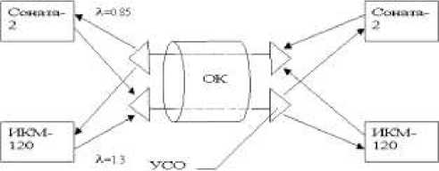
Fig. 1. The scheme of the organization of a light path with spectral consolidation
On communication networks single – fiber FOCS with optical splitters and with spectral consolidation find application. For the first time almost spectral consolidation is realized on one of fiber optic of systems of transfer of LN in Petersburg. Here apply the domestic equipment - a four-fiber optical cable, equipment "Sonata-2" (length of a wave of 0.85 microns) and IKM-120-4/5 (length of a wave of 1.3 microns). As devices of spectral consolidation, devices of spectral association and division USOD-0.85/1.3 were used. They represent the passive optical devices providing with the help - an interferential optical filter association in one OF and division of signals from bearing on waves 0.85 and 1.3 microns. The scheme of the organization of a light guide path with spectral consolidation is shown on fig. 1.
The first stage at design of the schematic diagram of the FOCS sending device is the choice of type and brand of an optical radiator proceeding from requirements shown to its technical characteristics. The main technical characteristics of radiators treat:
-
V radiation capacity;
-
V length of a wave of radiation;
-
V width of a range of radiation;
-
V frequency of modulation;
-
V rating current;
-
V threshold current
2.
The schematic diagram of the optical sending device in FOCL
For a right choice of an optical radiator, first of all it is necessary to be set by true value of capacity of radiation. For this purpose, it is necessary to define the demanded optical capacity on an exit of the optical sending device. The final decision about a choice of this or that brand of a radiator is accepted on the basis of compliance of technical characteristics of the device to the demanded length of a wave of radiation, width of a range of radiation and time of increase of capacity of an optical signal [2-4].
The second stage is the VT1 transistor choice in the scheme of the direct modulator (MOD) and modulator calculation (the Fig. 2). The transistor choose proceeding from characteristics of the optical radiator defined at the previous stage, namely a current of a rating and a threshold current. Thus, it is necessary to consider the most admissible capacity of the transistor and its boundary frequency. Then the working point is set and settled invoice elements of the scheme of the modulator.
At the third stage, it is necessary to calculate the coordinate amplifier (CA). Expedient use of the high-speed operational amplifier who has been switched on the scheme of the converter tension - a current (fig. 2) here is represented. It is required to choose correctly type of the operational amplifier according to demanded top frequency and the disseminated capacity, and also to calculate elements of the scheme of the converter tension - a current.
The fourth stage - the organization of the device of automatic adjustment of level of an optical signal on a sending device (AAL) exit. The VD2 photo diode connected to one of poles of the directed optical ramified (OR) and the detector AAL, (fig. 2) executed on integrated scheme К175ДА1 will be used for this purpose.
+12В
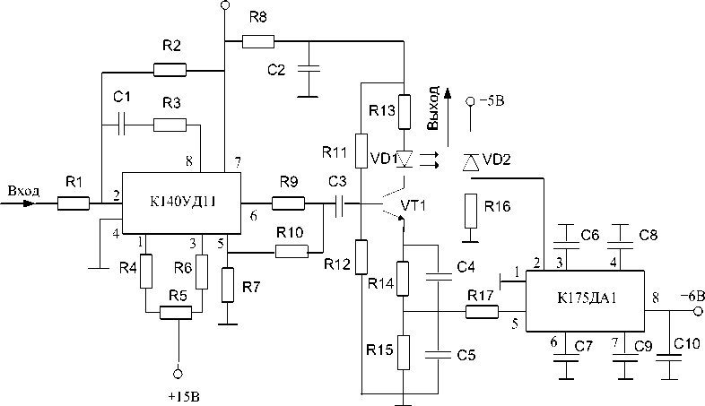
Fig.
Boeing 777 was the first commercial plane with a fiber optical local onboard network of data transmission. The system was initially developed in 1980х years and consisted their aviation local network (AVLAN) placed in the dashboard of a cabin of crew and a compartment of the electric equipment, and also a network of salon of the plane (CABLAN), placed under a ceiling of a passenger compartment of the plane. These two fiber-optical networks satisfy to the ARINC 636 standard which is adapted for aircraft the interface (FDDI), giving opportunity to support speeds of data transmission to 100 Mbp/s.
FDDI (Fiber Distributed Data Interface - the Fiber-optical interface of data transmission) is the reliable, high-speed interface, allowing solvation problem of the organization of local networks of data transmission. He allows to transfer data with speed to 100 Mbps and to support to 500 knots in one network. FDDI was developed for work with fiber-optical cables, to transfer on them the light impulses transferring information between stations, but he also allows working with copper conductors, using electric signals.
FDDI provides high reliability as it consists of two rings on which information is transferred in opposite directions. These rings carry out function of reservation of each other so if with a network, something happens, always it is possible to find an alternative way of data transmission. Use of possibility of selfdiagnostics of the FDDI network, also increases its reliability.
Thus, FDDI uses topology a double ring. Routable stations with double connection in a network are connect to these both rings.
Stations with double connection to a ring have at least two ports: port A where the entrance of primary ring and an exit of a secondary ring, and port B where the entrance of a secondary ring and an exit of primary ring settles down settles down. Stations also can have ports M, which are connect to stations with single connection.
Stations, which contain, at least one port M, are called as concentrators.
The sequence, according to which stations get access to the data transmission environment, is defined previously. The station forms special sequence of signals called a marker, which operates the transfer direction. The signal of a marker is continuously transferred on a network from one knot to the following. When the station transfers something, it accepts a marker signal, and transmits a signal in shots of FDDI of the correct format.
The heading of this shot includes the address of station (stations) which will copy this shot. All knots read out a shot when it passes through them at movement on a ring, for definition of, whether is this shot is intended for them or not.
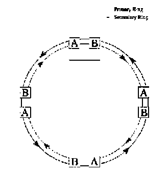
Fig. 3. FDDI network topology
If yes, that they take data and transfer a shot to the following knot in a ring. When the shot comes back to the station, which have transferred it, it deletes this shot. The scheme of go-ahead access, thus allows all stations to get the joint ordered and effective access to all pass-band of a network.
Fiber-optical tire
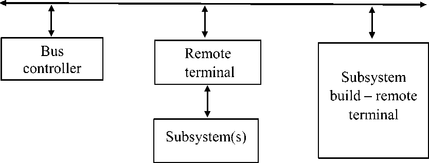
Fig. 4. Standard structure of the fiber-optical tire of the data defined by the MIL-STD-
1773 interface
MIL-STD-1773, Digital Internal Time Division Command/Response Multiplex Data Bus (The digital internal tire of data with temporary division and Team/answer type multiplexing) - a military standard which becomes one of the main tools used today by the Ministry of Defense of the USA for association of systems of arms. The standard describes a way of communication and the requirement to electric characteristics of the interface for the subsystems connected to the tire of data (fig. 4).
References Researching of the sending device of the fiber-optical communication line
- «Волоконно-оптические линии связи». Справочник. Под ред. Свечников С.В. и Андрушко Л.М., Киев. «Тэхника», 1988.
- Богачков И. В., Н. И. Горлов. Компоненты волоконно-оптических систем передачи и методы контроля их параметров: монография. - Омск: Изд-во ОмГТУ, 2011. - 200 с.
- Скляров О.К. Волоконно-оптические сети и системы связи. - М.: Солон-Пресс, 2004. -272.
- Гордиенко В. Н. Многоканальные телекоммуникационные системы: Учебник для вузов. - М.: Горячая линия - Телеком, 2007. - 416 с.
- Optical Fiber Telecommunications. V-B. Systems and Networks / I. Kaminov, et al. - Academic Press, 2008. - 916 pp.
