Resolver-to-digital converters with the arctangent function transformation

Author: Balkovoy A.P., Yurasova E.V., Smirnov Yu.S.
Section: Приборостроение, метрология и информационно-измерительные приборы и системы
Article in issue: 3 т.16, 2016.
Free access
The work is devoted to the peculiarities of the construction of amplitude converters of type “angle-parameter-code”, in which arctangent function transformation is used when converting output signals of a resolver into a digital equivalent of movement. The features of the construction of brushless classical resolvers and varieties of their variable reluctance, in Russia known as reductosin, are considered. It allows to realize an electrical reduction, at which the sensor accuracy increases considerably. The principle of operation of the resolver, output signals of which contain reliable information about components of displacement of the rotor, is found out. Resolver-to-Digital Converter (RDC) corresponds to the postulate of the general theory of relativity on communication of space and time. A special place among one-component “angle-parameter-code” converters is held by the structures using arctg-conversion, at which quadrant or octant range splitting of the transformation of angular displacement is used. In the first case, angular transformation is implemented by the digital signal processor (DSP) or microcontroller, and in the second one - by ROM with arctg insertion. The structure and ratios necessary for calculation of movement by software and tabular implementation of arctangent function transformation. An original version of the analog-to-digital converter with arctg ROM is presented. Its capacity at identical length of the output code is four times less than the capacity of traditionally used ROM with a sine-cosine firmware. Octant representation of a full range transformation of the angle of rotation allows to generate an additional high order digit of the output code in comparison with a traditional quadrant band splitting. This not only improves the resolution of the conversion twice, but also simplifies coordination of samples at application of an electrical reduction with the reductosin.
Esolver-to-digital converters, classical and variable reluctance resolvers (reductosin), pulsewidth modulation, brushless motors, arctangent function transformation, adc voltage ratios, read-only memory
Short address: https://sciup.org/147155138
IDR: 147155138 | UDC: 681.5.58 | DOI: 10.14529/ctcr160309
Преобразователи «угол - параметр - код» с арктангенсным функциональным преобразованием
Работа посвящена рассмотрению особенностей построения амплитудных преобразователей «угол - параметр - код», в которых при конвертации выходных сигналов резольвера в цифровой эквивалент перемещения применяется арктангенсное функциональное преобразование. Рассмотрены особенности построения классического бесконтактного резольвера и его разновидности - редуктосина, которые позволяют реализовать электрическую редукцию, существенно повышающую точность сенсора. Раскрыт принцип действия резольвера, выходные сигналы которого содержат достоверную информацию о составляющих перемещения ротора. Преобразователь «угол - параметр - код» соответствует постулату общей теории относительности о связи пространства и времени. Особое место среди однокомпонентных преобразователей «угол - параметр - код» занимают структуры, использующие арктангенсное функциональное преобразование, при котором используется квадрантное или октантное разбиение диапазона преобразования углового перемещения. В первом случае тригонометрическое преобразование реализуется цифровым сигнальным процессором или микроконтроллером, а во втором - посредством ПЗУ с арктангенсной прошивкой. Приведена структура и соотношения, необходимые для вычисления перемещения путем программной и табличной реализации арктангенсной функции. Представлен оригинальный вариант аналого-цифрового преобразователя с арктангенсной ПЗУ. Его емкость при одинаковой разрядности выходного кода в четыре раза меньше емкости традиционно используемого ПЗУ с синусно-косинусной прошивкой. Октантное представление полного диапазона преобразования угла поворота, позволяет сформировать дополнительный старший разряд выходного кода по сравнению с традиционным квадрантным разбиением диапазона. Это позволяет не только повысить разрешение преобразования в 2 раза, но и упростить согласование отсчетов при применении электрической редукции с редуктосином.
Text of the scientific article Resolver-to-digital converters with the arctangent function transformation
The scope of work is actual as it is devoted to energy informatics (energoinformational interaction) [1] of the electric drive [2] and mechartonic systems (MS) [3]. The analysis of publications devoted to the development, research and implementation of a dateware of the process of the conversion of energy in the functional movement of the working mechanism, possessing property of a chronotope, provides the following tasks:
-
- features of the resolver functioning and its construction [4–10];
-
- formation of the Common Dateware on the basis of the conversion corresponding to the general theory of relativity in terms of the postulate of time and space communication [11–16];
-
- as sensors at Common Dateware are used inductive [17], optical [18] and magnetic-field [19] sensors. Most widely used are Synhros and Resolvers (R), possessing remarkable properties and high performance criteria [2, 7].
Resolver is a 2-phase micromachine
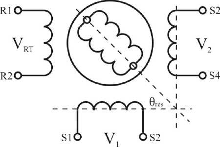
Resolvers are brushless type (Fig. 1) that is, the rotor excitation is ring transformer (RT) coupled to the shaft rotor winding. Many resolver applications operate with high speeds where the velocity error is significant source of measurement errors. Also, the signals of resolver are affected by the switching
Приборостроение, метрология
noise due to pulse width modulation (PWM) of the motor inverter [3, 4]. Paper represents a solution for measuring the resolver signals for electric drive application without being affected by the speed and the switching noise due to PWM of motor inverter.
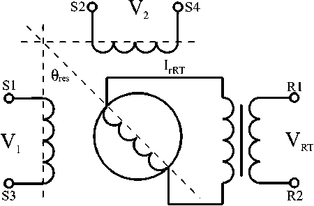
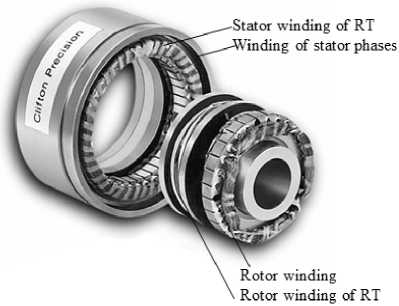
Fig. 1. The brushless classical resolver company Clifton Precision
The RT stator of brushless resolver (Fig. 1) is supplied from AC voltage V RT = VRTmsin ( Q et + ^e) of variable frequency Q e and phase shift of ^e. The RT stator and rotor currents are I sRT and IrRT = IrRTmsin ( Q et), respectively. Resolver is a 2-phase AC machine. So, the electrical equations for stator windings of this machine are:
V i = Rk + Lsk + s[(LmCOS p re s ® me )I rRT ] =
= RIi + LsI i
L m I r RT pres ^ me
sin P res ® me
+ Lm(cospres ® me)( ^ IrRT) ;
V i = RI2 + LsI2 + s[(L m Sin P res ® me )I rRT ] =
RI2 + L$k + LmIrRT pres ^ me cos pres ® me + Lm(sinpres ® me)( ^ IrRT) ,
where Q me is the mechanical speed; ® me is the mechanical angle; p res is the resolver number of poles; Vi, V2; Ii, I2 are the voltages and currents of stator 1 and 2 windings; R is the stator winding resistance; L is the stator winding inductance; L m is the amplitude of mutual inductance of stator windings and rotor winding; s = d/dt .
In the no-load condition (high impedance of measuring circuits), for stator windings there will be no current and the current derivatives will be also zero (Ii = I2 = sI i = sI 2 = 0). So, the equations (1) and (2) will be:
Vi = Lm (cos p res ® meX^rRT ) — LmIrRT pres ^ me (sin p res ® me ) ;
V2 = LmIrRT pres ^ me(cos pres ® me ) + Lm(sin pres ® me)( ^ IrRT) .
The voltages (3) and (4) have two components: the first one (back-EMF) depends of excitation frequency Q e (because IrRT = IrRTm sin Q et), speed ( Q me) and position ® res = pres ® me, the second one (EMF of transformation) depends of frequency Q e (because sI rRT = IrRTm Q ecos Q et) and position ® res = pres ® me. This property of the signals Vi and V2 allows to eliminate errors due to the speed Q me. In the case of synchronous sampling of both signals Vi and V2 when sin Q et = 0 and cos Q et = 1, the current IrRT = 0 and its derivative is maximal: sI rRT = IrRTm Q ecos Q et = IrRTm Q e. So, in (3) and (4), the back-EMF components will be absent and EMFs of transformation will be only position dependent with maximal amplitude V n = L m I rRTm Q e :
Vi = Lm(cos pres ® me)IrRTm ^ e ;
V2 = Lm(sin pres ® me)IrRTm ^ e .
From (5) and (6), the angle ® me = ® res/pres may be calculated using standard software decisions.
Variable reluctance resolvers (VRR) have no windings on the rotor. Their primary and secondary windings are all on the stator, but the saliency (exposed poles) of the rotor couples the sinusoidal variation in the secondary with the angular position Fig. 2) [5, 6].
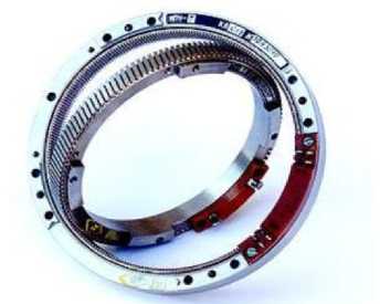
Fig. 2. Variable reluctance resolver (reductosin)
The structure of the RDC with digital signal processor
Converter realising the proposed method by DSP comprises (Fig. 3): exciting generator EG , DAC and analog voltage inverter AVI for R excitation; differential amplifiers DA 1 and DA 2 conditioning resolver output signals; ADC for converting of analog signals V i and У2 into digital form D i and D 2 ; decoder software DSW for calculating of resolver angle 0 res = ® me p r es from Di and D2.
RDC (Fig. 3) is capable of outputting a good resolver signals two times per excitation period without being affected by the motor speed and by the switching noise due to a PWM signal of an inverter. In the tested system, the 14-bit AD converter for data conversion was used. That means (4V/5Vyi6392= 13113 bit resolution for peak-to-peak of the measured signal. There are 360 x 60 x 60" (arc seconds) in the 32 periods (2 times peak-to-peak) of the resolver with 32 poles signal. So, one bit (resolution) of the ADC corresponds to 1,544" (arc seconds).
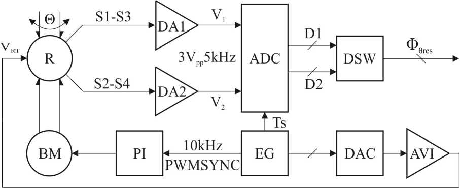
Fig. 3. Structure of the RDC with digital signal processor
An experiment has been set-up in order to validate the proposed solution. In this experiment, the modulation signal VRT and PWM noise were completely disappeared from the digital signals Di and D2. For what concerns the accuracy of the position measurement, a comparison between the processed resolver data and the incremental encoder data has been performed. The tests were done with mechanical speeds of 0,01 rad∙s–1 and 50 rad∙s–1 respectively. Very small differences between the two measurements were achieved. An off line calculation allowed to evaluate that the overall measurement error of the proposed RDC was contained within the 12 bit ADC error (6 arc seconds of the rotating angle) and was speed independent.
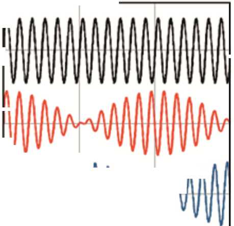
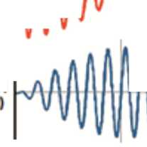
The resolver and RDC working principle of is as follows Fig. 4.
Приборостроение, метрология
The two output signals are modulated by the sine and cosine of the shaft angle. A graphical representation of the excitation signal and the sine and cosine output signals is shown in Fig. 4a. The sine signal has maximum amplitude at 90° and 270° and the cosine signal has maximum amplitude at 0° and 180°.
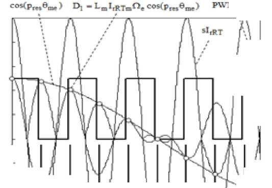
On the Fig. 4b the excitation current derivative sI rRT , the PWM synchronism signal (PWMSYNC), sampling signal periods T s , cosine signal of position cospres θ me , output voltage V 1 and digital signal D 1 of 32-pole pair resolver after AD conversion by the motor speed of 937RPM and T s = 100 µ s.
|
=■■1 O’ 90’ 180’ 270’ |
co^Pr*^) D1 -L.I.R^a.eoKp,,,©™.) PWMSYNC 0 2T. 4Г. 6T. 8T. |
Fig. 4. Resolver and RDC working principle
The important feature RDC with digital signal processor
The first important feature of the used method is tuning of excitation voltage V RT zero in the sampling period ( T s ) of DSP for getting the maximal amplitude of resolver output signals V 1 and V 2 in the sampling moments T s . This tuning is done by the phase shift of V RT in the sampling period of the DSP during slow rotation of the motor. Tuning is finished by the maximum amplitude of signals V 1 and V 2 in the sampling moments T s . Such procedure gives in the sampling moment the extremum of derivative of resolver rotor current sI rRT , zero of resolver rotor current ( I rRT = 0) and zero back-EMFs in V 1 and V 2 – see (3) and (4).
The second important feature of the used method is synchronisation of PWM synchronism signal PWMSYNC with founded moment of resolver excitation. The PWM synchronism signal leading edge is tuned to get the minimal noise of measured signals. So, the system measures the resolver signals without being affected by the switching noise of inverter PWM . This phasing avoids the PWM interference on the resolver signals.
The third important feature of the used method is double sampling per excitation period. Position data D1 and D2 are read each sampling period at the time moments when the output signals amplitude is maximal. By the next sampling, the position data D1 and D2 are read as – V1 and – V2. So, digital signals D1 and D2 after conversion will have the amplitude modulated waveform of the exciting signal corresponding to the rotating angle ©res = ©mepres of the resolver as shown in Fig. 4b.
It is possible to calculate the angle, using a large number of known algorithms and various hardware [2, 3]. The simplest of these algorithms is a four-quadrant arctan signal conversion: © me P res = arctg^ l /^).
Calculation of the function arctg(β) by algorithmic and tabular methods
The series expansion of the function arctg(β) is carried out on [17]:
arctg ( P ) =f ( - 1 ) k -P 2 k + 1 /( 2 k + 1 ) .
k = 0
In the range of angles from 0 to 45 degrees for resolution of 20 bits 5 first members of a row are enough, taken with a 32-bit accuracy. Thus, after the measurement with the ADC, the calculation of the angle and its representation in the form of 0 to 1 for values from 0 to 2π takes 2 operations of normalization, one division, 5 multiplications, up to 8 additions and to 7 logical transitions on a short address. In total, no more than 40 cycles of a processor such as ARM Cortex-M3. For reduction of calculations Heron's formula is used. The calculations are integer (32 bits) with the normalization of up to 16 bits.
At calculation by the tabular method, the oktant with a required angle is determined by measured values of Vsin and Vcos and on the relation of values | Vsin | and | Vcos | the required angle is calculated by one of formulas [17]:
to Vsin > 0 and Vcos > 0 and to Vsin > 0 and Vcos > 0 and to Vsin < 0 and Vcos > 0 and to Vsin > 0 and Vcos > 0 and to Vsin > 0 and Vcos < 0 and to Vsin > 0 and Vcos < 0 and to Vsin < 0 and Vcos < 0 and to Vsin < 0 and Vcos < 0 and
Vsin I < I Vcos |, then ф = в,
Vsin I > I Vcos |, then ф = п/2 - в, Vsin I > I Vcos |, then ф = - в, VsinI < | Vcos I, then ф = -п/2 + в Vsin | > | Vcos I, then ф = п/2 + в, VsinI < | Vcos |, then ф = п - в, Vsin I < | V cos|, then ф = -п + в, VsinI > | Vcos |, then ф = -п/2 + в
where β – an angle in the range of 0…45 degrees (0…π / 4).
Further the value of tg(β) = |Vsin| / |Vcos| is calculated and according to the table, depending on tg(β1), the value of β1 is found, where tg(β1) – the nearest smaller tabular value of a tangent of angle, and a required angle
β = (tg(β) –tg(β1))(C0 + C1∙β1 + C2∙β1), where C0, C1, C2 – correction coefficients of correction of the algorithm error function. Such method provides resolution of 16 bits at the table size in 256 values.
Resolver-to-Digital Converter with arctangent ROM
Application of DSC (Fig. 3) or ARM to evaluate the function β = arctg β within an octant in the algorithmic or tabular way leads to the reduction of the converting rate. Therefore, RDC with ROM should be preferred in high-speed MS. In MS, where “autophasing” [2] is not required, information on movement for self-switching of the electric motor can use the simplified algorithm of converting with arctg ROM. The offered [10] actantial representation of a full range of transformation, instead of a quadrant, at an equal speed allows to form additionally 3 highest weight discharge angles © .This is important in case of creation of a two-speed RDC, in which an additional bit is used for the matching of fine and coarse reading of MS. Speed of the conversion of output signals of resolvers to the digital equivalent of movement is also defined by speed of ADC of the relation of segments of tension in an octant.
In the scheme shown in Fig. 5 in the first stage output signals of resolver R are converted to a code of a tangent of angle tg P = V s /P c , where p - the angle of rotation 0 , given in the first octant. Simultaneously, the formation of three high-order digits of the angle Ф0 is carried out. RDC works as follows. Two signals, proportional to the current value of sin S and cos C of the angle 0 , arrive on inputs of the analog switchboard and the detector of octants DO .
Their preliminary conversion is carried out either by individual demodulators DM of output signals of the resolver R or by peak detectors of the “memory access” type [10]. Three high-order digits of the code of the angle 0 are formed from the number of the octant. By comparison of output signals of the resolver R with each other and with a zero-level number of the octant is defined, which contains
References Resolver-to-digital converters with the arctangent function transformation
- Энергоинформатика. Большая энциклопедия: в 62 т. -М.: ТЕРРА, 2006. -Т. 6. -С. 440.
- Балковой, А.П. Прецизионный электропривод с вентильными двигателями/А.П. Балковой, В.К. Цаценкин. -М.: ИД МЭИ, 2010. -328 с.
- Balkovoi, A.P. A low cost RDC/A.P. Balkovoi, E. Kallenbach//Proc. of the 49th International Scientific Colloquium, Technical University of Ilmenau. -2004. -P. 338-342.
- Drury, B. The Control Techniques Drives and Controls: Handbook/B. Drury. -2nd ed. -EMERSON. JET, 2009. -724 p.
- Cronacher, G. Design, performance and application of the Vernier resolver/G. Cronacher//The Bell System Technical Journal. -1957. -Iss. XXXVI, vol. 6. -P. 103-112.
- Precision Resolver-to-Digital Converter Measures Angular Position and Velocity/J. Szymczak, Sh. O’Meara, J. Gealon, C. De La Rama//Analog Dialogue. -2014. -48-03, March. -P. 1-6.
- Смирнов, Ю.С. Электромехатронные преобразователи/Ю.С. Смирнов; под ред. А.Л. Шестакова. -Челябинск: Издат. центр ЮУрГУ, 2013. -360 с.
- Spetzer, J. Resolvers. Things you need to know about sizing and applying/J. Spetzer, W. Ekhaml//Motion System Design. -2001. -March. -P. 61-64.
- Smirnov, Y.S. Common Dateware Mechatronic with Resolver-to-Digital Convertor/Y.S. Smirnov, V.V. Safronov, Y.O. Anisimov//International Conference on Industrial Engineering, ICIE 2015. Procedia Engineering. -2015. -Vol. 129. -P. 736-742.
- Сафронов, В.В. Теория и практика применения датчиков угла поворота на основе СКВТ/В.В. Сафронов//Компоненты и технологии. -2014. -№ 4. -С. 26-30.
- Smirnov, Y.S. Common Dateware of Robotics Mechatronic Converters/Y.S. Smirnov//Proceedings of the Third ISMCR’93. Torino, Italy, 1993. -P. 13-18.
- Домрачев, В.Г. Схемотехника цифровых преобразователей перемещений/В.Г. Домрачев, В.Р. Матвеевский, Ю.С. Смирнов. -М.: Энергоатомиздат, 1987. -392 с.
- Goodenough, F. ICs dictate motor shaft position, velocity and acceleration/F. Goodenough//Electronic Design. -1988. -Vol. 36, no. 3. -P. 50-52.
- Домрачев, В.Г. Цифроаналоговые системы позиционирования. Электромеханотронные преобразователи/В.Г. Домрачев, Ю.С. Смирнов. -М.: Энергоатомиздат, 1990. -240 с.
- Способ измерения угла поворота вала привода и устройство для его реализации: пат. 2580153 Российская федерация, G01B7/30/В.В. Сафронов; заявитель и патентообразователь ФГУП «ЦНИИМаш». -Заявл. 25.11.14; опубл. 10.04.16, Бюл. № 10. -С. 3.
- J. Sylvan. New Option for Resolver-to-Digital Conversion. Machine Design,1987, October, pp. 141-146.
- Ануфриев, В. Методы обработки сигналов индуктивных датчиков линейных и угловых перемещений/В. Ануфриев, А. Лужбинин, С. Шумилин//Современная электроника. -2014. -№ 4. -С. 30-33.
- Balkovoy, A. Sinusoidal incremental encoder date processing/A. Balkovoy, G. Slivinskaia//Proceedings of the 48th International Scientific Colloquium. Technical University of Ilmenau, 2003. -P. 111.
- Специфика применения синусно-косинусных сенсоров/Ю.С. Смирнов, Е.В. Юрасова, Е.В. Вставская, И.С. Никитин//Материалы конференции «Информационные технологии в уп-равлении» (ИТУ-2014). -СПб.: ОАО «Концерн «ЦНИИ «Электроприбор», 2014. -С. 720-729.
- Наука. Величайшие теории: вып. 1: Пространство -это вопрос времени. Эйнштейн. Теория относительности. -М.: Де Агостини, 2015. -176 с.
