Resource Optimization for the Efficient Channel Access and Estimation in LTE System

Author: Manorama.Setia, Jyoteesh.Malhotra
Journal: International Journal of Image, Graphics and Signal Processing(IJIGSP) @ijigsp
Article in issue: 12 vol.7, 2015.
Free access
LTE Standard has been an inseparable part of 3GPP that was started with an objective to upgrade 3G based Mobile Systems to 4G.This standard has been developed to enhance the data rate, reliability and seamless connectivity to the users. There is a need to evaluate the achievable performance through this standard in terms of MAC parameters. Moreover, in order to optimize the resources like Power and Bandwidth, Extensive Simulations have been done here considering the Medium Access techniques like Channel estimation, Retransmission techniques and Scheduling techniques. Two Scenarios have been designed by considering diverse Conditions of Physical Layer Resources. Optimal Performance bounds have been obtained in terms of BLER and throughput for the proposed Scenarios.
LTE, QOS, FIFO, CQI, HARQ
Short address: https://sciup.org/15013932
IDR: 15013932
Text of the scientific article Resource Optimization for the Efficient Channel Access and Estimation in LTE System
Published Online November 2015 in MECS
As the world is becoming the internet generation, more and more data is processed through wireless communication. So development in wireless communication is moving in an extremely instantaneous speed for achieving good capacity, efficient system, and high data rate. This standard is making development towards the introduction of 4G so that future demand of interactive TV, advanced remote controlling, mobile video blogging should be fulfilled [1]. The main objectives of LTE include minimum delay, high data transmission rate, high spectral efficiency and the Resource management is the very important part to maintain QoS and achieve the high level requirements of LTE. In order to fulfill their demand LTE adopts OFDMA technology in downlink and SC-FDMA in uplink transmission, MIMO for more robust system. [2] Parameters for maintaining quality of service are scheduling, channel estimation, HARQ is considered. The Scheduling is done to assign resources to all users they are rr (round robin) and Best CQI in which rr is known for fairness and best CQI is for high average throughput. Channel estimation is a technique for removing noises which get introduced on the way. Estimation techniques are LS, MMSE, and PERFECT in order to reduce difference between transmitted and received signal. HARQ is for maintaining quality of signal which is working with ACK, NACK which will transmit same data as it get NACK it give quality of service at the expense of resources. Indicators like CQI, PMI and RI are used for giving the indication of quality of the link.
LTE is constantly working in the field of QoS by proposing new estimation techniques, with scheduling techniques like max throughput, with good fairness and throughput combo which motivates to enhance this area with more good results and achieve 99% QoS propaganda under LTE.
New scheduler has been proposed recently M.S Bahreyni [3] which provide resources to those who consume less B.W and in general give resources to all the user irrespective of how its performing
There is a need to optimize the performance of different MAC techniques for efficient utilization of resources. R.D Trivedi [4] evaluated one MAC technique (HARQ) performance for three different Scenarios which vary in distance. In this paper holistic approach has been used by considering three MAC techniques that are evaluated for two different Scenarios which differs in number of parameters from each other with the help of LTE link level simulator.
This paper Contributes deeply by evaluating the MAC techniques for different Scenarios, in which physical resources for different conditions are formed through which performance bound over power and spectrum efficiency is obtained.
The paper is organized in sections as, in section II provides basic introduction to MAC techniques. Section III gives the values of environment under which simulation is under taken and Section IV concludes the paper.
-
II. Related Work
In [4] R.D Trivedi evaluated (HARQ) MAC technique for three different Scenarios of different distances. Similarly in [5] M.T Kawser evaluated the throughput performance of Schedulers in different transmission modes for system level.
-
III. MAC Techniques
Medium Access techniques work on medium access layer which deal with Channel Access techniques. Scheduling, repeat transmission, and channel access estimation technique which all have main aim of QOS. In this section detail study of these MAC techniques is given
-
A. Scheduling techniques
A.a. Round Robin
This is simple and fair scheduler but in this throughput doesn’t have worth because it works without under taking channel conditions and assign the resources to all the users by following cyclic pattern.[5] It is also known by non-aware scheduling [4]. It is implemented under time domain as well as combination of time and frequency domain. In time domain it doesn’t consider channel condition and provide resources fairly according to FIFO. The served user will be sent to last in queue for next turn and in other case it will give turn to multiple users in single TTI. [6]
A.b. Best CQI
It is opposite to round robin scheduler as it considers only link condition no matter who is on the turn. It provides resources to the link with highest CQI among all. So for CQI, feedback is required from ue to e-NodeB. Higher CQI represents the better channel conditions. In this the throughput increases efficiently but the fairness towards users is neglected and moreover the edge users get totally neglected due to their distance. [3]
-
B. HARQ (Hybrid automatic repeat request)
It is a technique combined FEC (forward error correction) of wired communication with ARQ (Automatic repeat request) called HARQ.[7]HARQ uses ACK and NACK. It is an asynchronous process both in uplink and downlink, where asynchronous means timing is flexible but signaling should be synchronous. They require additional resources for their process but it is necessary part for achieving good reliability. [8]
-
C. Estimation techniques
It’s a most important part on the receiver side to estimate the signal which gets affected while passing through the channel. It uses pilot signals to estimate the channel and these signals are called reference signals. [9]It is basically noise rejection scheme which remove ISI in order to maintain QOS and achieve high throughput. With this technique decoding at receiver get improved [10] and the received signals are representing their pilot signals as shown in (1)
Y p =X p . H p +µ p (1)
C.a. LS (Least square)
Main motive is to minimize the difference between received signals from transmitted signal. The LS estimate of the pilot sub carrier as shown in (1) and is obtained as shown in (2)
C.b. MMSE (Minimum Mean Square Error):
It is more complex in calculation as compared to LS but provide improved performance. It basically differs by LS by considering the effect of AWGN added on the way or in the path of channel and the reason of its complexity is it requires extra information for good estimation which requires a backend and thus overload the communication because of its backend maintenance and as the name depicts it estimates the signal by minimizing the mean square error which is defined as in (3)
MSE=E {|He-H|2} (3)
He = estimated attenuation vector
H= true with attenuation vector
C.c. Perfect
In this estimation technique it works as its name is defined ‘perfectly’ because it maintain the whole knowledge of channel but it is different from MMSE because that require correlation and SNR data but in this technique whole knowledge of channel is required [11].
-
IV. Simulation Environment and Methodology
Simulator is the model for evaluating the communication of signal before implementing it in the realistic environment. Simulating environment consist of no of antennas, channel, no. of users, bandwidth, no. of resources all these parameters are considered and for evaluating our results, in this research LTE link level simulator is opted for practical results.
-
A. Realistic channel (PedB)
ITU specified models are empirical models. It is also defined as indoor to outdoor office pedestrian. Pedestrian refers to person who goes on foot. In this for LOS transmission path loss exponent is considered to be 2 and for NLOS or area which is obstructed by trees or any other interference is having path loss exponent =6 and number of paths defined for Pedestrian B is 6.
-
B. Simulating environment
The environment setup for this simulation is divided into two scenarios, scenario-1 is having difference from scenario 2 in terms of resources value in which CQI, Transmission Mode, Fading channel, Bandwidth, no. of users and e-NodeB is considered. And for them quality parameters like HARQ, channel estimation scheduling etc is evaluated scenarios I and II are shown in Table I
Table 1. Scenario I and II for the Simulating Environment
|
Scenario I |
Scenario II |
||
|
Parameters |
Values |
Parameters |
Values |
|
CQI |
7 |
CQI |
10 |
|
Bandwidth |
3 MHz |
Bandwidth |
3MHz |
|
Transmission mode |
111(SISO) |
Transmission mode |
422(CLSM) |
|
Channel estimation |
LS, MMSE, Perfect |
Channel estimation |
LS, MMSE, Perfect |
|
HARQ |
0,1,2 |
HARQ |
0,1,2 |
|
Channel scheduler |
rr, best cqi |
Channel scheduler |
rr, best cqi |
|
Modulation type |
16 QAM |
Modulation type |
64 QAM |
|
No of UE |
1 |
No of UE |
2 |
|
No. of tx at BS |
1 |
No. of tx at BS |
4 |
|
No. of Rx |
1 |
No. of Rx |
2 |
-
C. Simulation Methodology
-
1. Set the global variables clear all, with clear all garbage values from the buffers.
-
2. Set the Debug level to highest value
-
3. Set the resources which are fixed accordingly u select scenario 1 or senario2
-
4. Check transmission mode>=200
-
5. Set no of retransmission vector (0, 1, 2, 3)
-
6. Set the variable quality parameters
Simulation =SUMIMO;
Else
Simulation =SUSISO;
-
• SWITCH scheduler
-
■ Case round robin
Switch scheduler assign
-
❖ Case static
Static scheduler = true;
-
• Get a vector of scheduling parameters
-
• Fill in the resource block allocation grid for each user
-
• Assign static scheduling parameters for each user.
-
❖ Case dynamic
Static scheduler= false;
-
■ Case best CQI
-
• Fill all basic parameters
Static parameters = false;
-
• Calculate quality of link by using PMI,RI or CQI indicator
For u = 1: no. of UE
Calculate sum efficiencies for both code words on every resource block
End (Decide which UE gets which Resource block)
For r=1: no. of RB
This converts randomization into decision to make scheduling fair to handle the case of equal CQI’s
End
> SWITCH estimation
-
• Case LS
-
I. Locate the reference symbols
-
II. Convert position of reference symbol into appropriate matrix
-
III. Then refers symbol in terms of frequency
-
• Case MMSE
Firstly LS estimate on the positions of symbols, then again same procedure of reference symbols
-
• Case PERFECT
-
7. Results will be save in .mat file
-
8. Results will be plot in terms of BLER and throughput.
In this all knowledge of channel is with estimator in advance.
-
V. Results and analysis
In this section results based on two scenarios set for the simulation to evaluate the QoS in fixed physical resources. This simulation helps us to evaluate performance bounds of MAC access techniques to be obtained in specific physical resources. These results are obtained with the help of LTE link level simulator. Scenarios are explained in above section .So firstly the Scheduling is considered for evaluating the QoS in which two schedulers are taken round robin and best cqi. Fig. 1 and 2 showing the BLER and throughput performance of scenario I which is for single user and CQI=7 .In this round robin is performing good in terms of BLER after SNR=1.5 db it starts gradually decreasing, Whereas Best cqi is fluctuating over one value and it is performing poor in terms of BLER as error >10-1
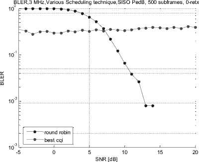
Fig.1. BLER Performance of Various Scheduling Technique for Scenario I
In throughput results Best CQI performing best among all schedulers as it is less fair than round robin. With round robin giving max throughput of 3.5Mbps as compared to Best CQI which is giving 5.5 Mbps.
throughput, 3 MHz,Various Schedulers,SISO PedB,500 subframes, 0-retx
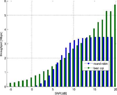
Fig.2. Throughput Performances of Various Scheduling Technique for Scenario I
throughput, 3 MHz,Various estimation,SISO PedB,500 subframes, 0-retx
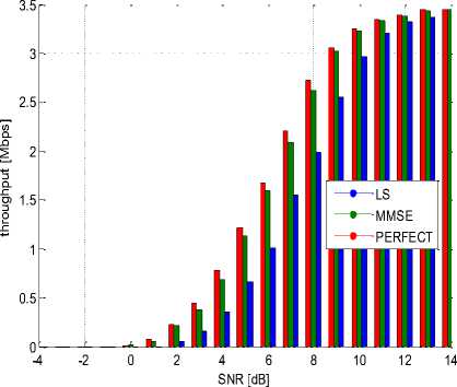
Fig.4. Throughput Performances of Various Estimation Techniques for Scenario I
Next estimation techniques are taken in consideration in which LS is simple in implementation and less efficient and MMSE and PERFECT is complex in implementation but much efficient in performance.
In Fig. 3 and 4 next technique is considered ,that is estimation .In this three estimation techniques are considered LS,MMSE and PERFECT and evaluate their results for Scenario I .Fig. 3 is showing BLER comparison of all 3 techniques .MMSE and Perfect is performing best by reducing to lower value of BLER with less power dissipation. Whereas LS require approximately 1.5 db power more to reach at same reduced value.
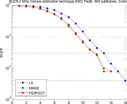
SNR [dB]
Fig.3. BLER Performances for Various Estimation Techniques for Scenario I
Similarly in Fig. 4 Perfect and MMSE performs equally and efficiently, even max value reached by all techniques is 3.5 Mbps. But Perfect and MMSE starts approaching towards it at low SNR, LS require 1 db more power to reach at same value of throughput.
Further retransmission effect is consider t he QOS which varies from 0 to 3 and 3 is max. value of retransmission but it require high reserve resources.
SNR [dB]
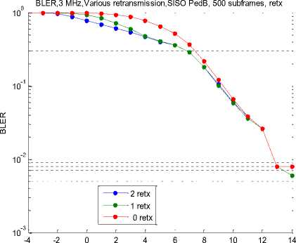
Fig.5. BLER Performances of Various Re-transmissions for Scenario I
In Fig. 5 and 6 Retransmission technique is considered, whose max value is 3 but it requires reservation in resources. Performance gets improved by using retransmission but it is not substantial. In Fig. 5 retransmission 1 and 2 are performing better as compare to 0 re-transmission and this variation is also for error <10-1 initially difference was 5 db between 0 and 2 re-tx after SNR=10 and BLER <10-1all performs identically. Fig. 6 is evaluating the throughput performance of these retransmission values. It is clear from the figure that with 2 retransmission it starts increasing at SNR= -2.5 db only but within 5-10 db it start increasing very slowly and finally through each retransmission it reached to 3.5 Mbps.
throughput, 3 MHz,Various Retransmission,SISO PedB,500 subframes, retx
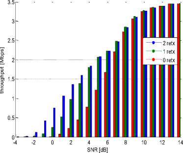
Fig.6. Throughput Performance of Various Retransmission of Scenario I
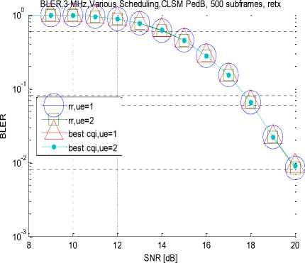
Fig.9. BLER Performance of Various Scheduling Techniques for Scenario II
After evaluating QOS parameters for Scenario I same parameters will be evaluated for Scenario II in which MIMO is taken and users also increased as well as coding efficiency is improved. Firstly estimation techniques are taken in consideration. In Fig.7 and 8 BLER and throughput performance is evaluated in Scenario II .similar to scenario I Perfect is performing good but as in this scenario no. of User equipments are increased it requires more SNR to decrease and reduced to very low value in SNR =8 to 20 as compare to scenario I and in terms of throughput also
In Fig 9 and 10 shows the performance of various schedulers in Scenario II .Fig. 9 is showing the BLER performance of round robin and best CQI which is revealing that best CQI performance becomes equivalent to round robin whereas in Scenario I performance of Best CQI is worst as compared to round robin
Hz,Various estimation,CLSM PedB, 500 subframes, retx
10-1
10-2
ч- PERFECT,ue=1
—е—PERFECT,ue=2
LS,ue=1
—•— LS,ue=2
—•—MMSE,ue=1
10-3
10 12 14 16 18 20
SNR [dB]
Fig.7. BLER Performance of Various Estimation Techniques for Scenario II
throughput, 3 MHz,Various Scheduling,CLSM PedB,500 subframes, retx
SNR [dB]
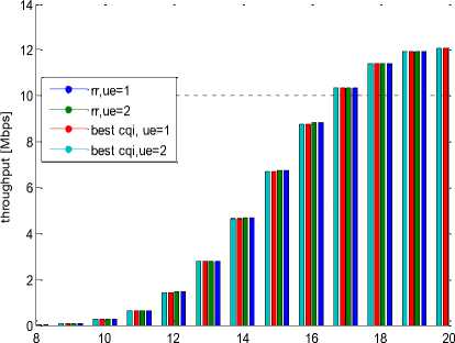
Fig.10. Throughput Performance of Various Scheduling Technique for Scenario II
throughput, 3 MHz,Various estimation,CLSM PedB,500 subframes, retx
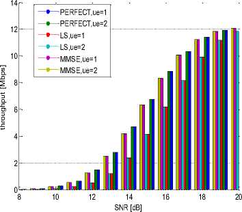
Fig.8. Throughput Performance of Various Estimation Techniques for Scenario II
But in Scenario II channel quality get increased that’s why performance
Becomes equivalent. In Figure 10 throughput comparison of both schedulers is evaluated which becomes equivalent to 12 Mbps which is best results for round robin and overall throughput compared to Scenario I multiplies by 4.
In Fig. 11 and 12 shows the comparison of various retransmission for Scenario II which reveals that with increase in performance of channel quality, need for retransmission of same signal reduces and saves resources earlier which have to be reserved for retransmission purpose only. In Scenario II error is reduced up to 10-2 which is comparatively less then Scenario I initially difference is approximately 5-6db between 0 and 2 re-tx and performance in terms of throughput get increased up to 12 Mbps.
BLER,3 MHz,Various retransmission,CLSM PedB, 500 subframes, retx
10-1
10-2
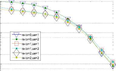
Table 3. Comparative Analysis of Scheduling Techniques
|
Parameters |
Scenario I |
Scenario II |
||
|
Schedulers |
BLER (10-2) |
Throughput (3.5 Mbps) |
BLER (10-2) |
Throughput (8Mbps) |
|
1. Round robin |
13.5 db |
12 db |
- |
16 db |
|
2. Best CQI |
- |
13 db |
20 db |
16 db |
Table IV shows the Comparison of retransmission techniques and at selected throughput =1 Mbps and BLER = 10-2
10-3
10 11 12 13 14 15 16 17 18 19 20
SNR [dB]
Fig.11. BLER Performance for Various Retransmissions for Scenario II throughput, 3 MHz,Various retransmission,CLSM PedB,500 subframes, retx
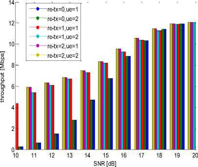
Fig.12. Throughput Performance for Various Retransmissions for Scenario II
Further in this Section only actually power required to achieve that particular BLER and throughput is compared in tabular form which will help in understanding these graphical comparison clearly
-
a. Comparison of parameters for Scenarios
Table II is comparison of different estimation techniques in which value at BLER =10-2 and throughput=3Mbps.
Table 2. Comparative analysis of estimation techniques
|
Parameters |
Scenario I |
Scenario II |
||
|
Channel estimation |
BLER (10-2) |
Throughp ut (3Mbps) |
BLER (10-2) |
Through put (3 Mbps) |
|
1. LS |
14 .5db |
10.5 db |
- |
14 db |
|
2. MMSE |
13.3 db |
8.3 db |
20 db |
12.5 db |
|
3. Perfect |
13 db |
8 db |
19.5db |
12 db |
Further in Table III Scheduling techniques are evaluated in which Scenario I is having max. Throughput = 6 Mbps and in Scenario II it is 14 Mbps and for comparison max. Throughput =3.5 Mbps in Scenario I and for Scenario II 8 Mbps
Table 4. Comparative Analysis of Retransmission Techniques
|
Parameters |
Scenari o I |
Scenario II |
Parameters |
Scenari o I |
|
Retransmissio n |
BLER (10-1) |
Throughp ut (1 Mbps) |
Retransmissio n |
BLER (10-1) |
|
0 |
9.5 db |
4 db |
0 |
9.5 db |
|
1 |
9 db |
2 db |
1 |
9 db |
-
VI. Conclusion
The main goal of the development of LTE System is to provide the users with QOS provisioned resource utilization. The power and Spectral efficiency need to be optimized for diverse conditions of channel and available resources. A lot of work has been reported in the literature for channel estimation, Scheduling techniques and HARQ for the robust and reliable channel access. In this paper the MAC techniques have been used to find out the optimum bounds for the resource utilization. Simulation results reviled for Scenario II which is better in all way as compared to Scenario I will give obvious hike in throughput which multiplies to4 i.e.12 Mbps but at same B.W. which is an extremely prominent achievement. In our observations, MAC techniques like scheduling results revealed that with good channel quality (High modulation scheme and good transmit diversity) round robin can performs equivalent to best CQI, For retransmission 1 or 2 is sufficient, no need for high retransmission is required with this step, resources will be saved and at last In estimation MMSE performs as good as perfect and it has no trade-off between BLER and throughput so it is efficient in both efficiency. Spectral efficiency for Scenario I is 1.666bps/Hz and 4 bps/Hz for Scenario II and Power efficiency of Scenario I is good as compared to Scenario II. The performance results obtained by our observations are of great importance and reference for the system engineers working in the area of mobile wireless system in general and specifically in LTE systems.
References Resource Optimization for the Efficient Channel Access and Estimation in LTE System
- L.Zhang, "A survey of LTE evolution", www.cse.wustl.edu, 2010.
- V. Sharma, Prof. P.K Chopra " A Survey on LTE Downlink Packet Scheduling", pp-7896-7899, IJARCCE, 2014.
- M. S Bahreyni, V. S. Naeini "Fairness Aware Downlink Scheduling Algorithm for LTE Networks", pp-53-63, JMCS, 2014.
- R.D. Trivedi, M. C. Patel "Comparison of Different Scheduling Algorithm for LTE", pp-334-339, IJEATAE, 2014.
- M.T. Kawser, H.M. A. B. Farid, A. R. Hasin "Performance Comparison between Round Robin and Proportional Fair Scheduling Methods for LTE", pp-678-681, IJIEE, 2012.
- M. H. Habaebi, J. Chebil, A.G. Al-sakkaf and T. H. Dahawi "Comparison Between Scheduling Techniques In Long Term Evolution", pp-66-75 IIUM, 2013.
- A. M. Cipriano, P. Gagneur "Overview of ARQ and HARQ in Beyond 3G Systems", pp-424-429, IEEE, 2010.
- Tumula V. K. Chaitanya "HARQ Systems: Resource Allocation, Feedback Error Protection, and Bits-to-Symbol Mappings", Communication systems, 2013.
- A. Khlifi and R. Bouallegue "Performance Analysis of LS and LMMSE Channel Estimation Techniques for LTE Downlink Systems",pp-141-149, IJWMN, 2011.
- H. M. Abd Elkader1, G. Mabrouk "Performance of LTE Channel Estimation Algorithms for Different Interpolation Methods and Modulation Schemes" pp-48-52, IJERD, 2014.
- F. Weng, C. Yin "Channel Estimation For The Downlink Of3gpp-Lte Systems", pp-1042-1046, IEEE, 2010.
- M. Setia, J. Malhotra "Error Rate Performance of LTE Mobile System through Realistic Fading Channel", pp-56-59, AJITC-2015.
