Review on nearest level modulation methods based on MMC

Author: Zhang Ruirui
Journal: Бюллетень науки и практики @bulletennauki
Section: Технические науки
Article in issue: 6 т.8, 2022.
Free access
In view of the relevant situation of offshore wind power research, development and construction at home and abroad, as well as the energy crisis facing the world, we have ushered in a new opportunity and outbreak period for the development of new energy. Therefore, higher requirements are placed on the power supply, and the key technology for the design of offshore wind power flexible DC transmission high-power converters is proposed. The Modular Multi-level Converter (MMC) topology can only use a lower switching frequency to obtain higher power Waveform quality. The output voltage waveform can effectively reduce the switching loss and filter capacity and improve the efficiency and economy of the converter. Among them, the method based on Level Modulation (NLM) is usually the preferred method. This paper introduces the topology and working principle of the modular multilevel converter (MMC) in detail and describes the improved modulation method for NLM in detail. The advantages, disadvantages and application occasions of different improved modulation techniques are summarized, which provides a reference for the engineering application of MMC.
Increase level number, modular multilevel converter, nearest-level modulation
Short address: https://sciup.org/14124430
IDR: 14124430 | UDC: 621:314.6 | DOI: 10.33619/2414-2948/79/47
Обзор методов модуляции ближайшего уровня на основе MMC
К источнику питания предъявляются повышенные требования, и предлагается ключевая технология для проектирования гибких преобразователей высокой мощности с передачей постоянного тока для оффшорной ветроэнергетики. Топология модульного многоуровневого преобразователя (MMC) может использовать только более низкую частоту переключения для получения более высокого качества сигнала мощности. Форма волны выходного напряжения может эффективно снизить коммутационные потери и пропускную способность фильтра, а также повысить эффективность и экономичность преобразователя. Среди них метод, основанный на модуляции уровня (NLM), обычно является предпочтительным методом. В статье подробно представлена топология и принцип работы модульного многоуровневого преобразователя (MMC), а также подробно описан усовершенствованный метод модуляции для NLM. Обобщены преимущества, недостатки и возможности применения различных усовершенствованных методов модуляции, что дает справочную информацию по техническому применению MMC.
Text of the scientific article Review on nearest level modulation methods based on MMC
Бюллетень науки и практики / Bulletin of Science and Practice
UDC 621:314.6
-
1.1. Overview. The issue of energy and environmental protection has always been a common concern of the world. In recent years, with the rapid development of social living standards, the progress of science and technology is also changing with each passing day [1, 2].
With the improvement of living standards, our demand for energy and electricity is also increasing [3].
The abundant offshore wind energy resources and the proposal of the national marine strategy also have new requirements for power transmission methods; flexible DC transmission can realize flexible complementation and coordination among new energy, energy storage, and loads on the DC side, improving large-scale After the renewable energy power is connected, the peak regulation pressure of the receiving end system reduces the disturbance impact of intermittent energy on the receiving end AC power grid [4, 5].
The development of flexible DC transmission technology has brought new changes to the future transmission mode and the construction of the power grid. Hope, so flexible DC transmission is one of the main research directions of electric power. In the field of high-voltage power transmission, the power transmission mode has developed so far, and a pattern of coexistence of AC power transmission and DC power transmission has been formed. Under certain circumstances, the technical and economic advantages of using High Voltage Direct Current (HVDC) are more prominent than those of high-voltage AC transmission. Since then, HVDC transmission has been developed rapidly around the world because of its characteristics of being suitable for long-distance transmission of active power and fast controllability [6].
Since traditional HVDC transmission uses ordinary thyristors without self-shutdown capability as commutation elements, only the turn-on of the elements can be controlled, and the turn-off of the elements is realized by the commutation voltage provided by the AC system [7].
Therefore, the traditional HVDC transmission system relies on a complete AC system to operate and requires a certain strength of the AC system to achieve commutation, which makes the traditional HVDC transmission objectively have some limitations [8]. After the 1990s, the voltage source converter high-voltage direct current transmission (VSC-HVDC) based on fully controlled devices has attracted attention and gained rapid develop. As a new type of MCs, the modular multilevel converter (MMC) was first designed by Lesnicar and Marquardt in 2003 [9].
It took the lead in proposing a new converter topology, the Modular Multilevel Converter (MMC). The MMC converter consists of multiple sub-modules (SM), each sub-module provides a capacitor voltage, and by switching the capacitors of many sub-modules, the output of the three-phase voltage on the AC side can be achieved while maintaining the voltage on the DC side. The unique working method of the MMC converter determines that the quality of the output waveform of the MMC is higher than that of the VSC converter, so there is no need to configure an additional AC side filter, which reduces the initial investment cost of the MMC-HVDC project.
The highly modular structure of MMC supports the design of sub-module unit redundancy and expansion, and can continue to operate normally by putting in redundant sub-modules to replace the faulty sub-modules when the sub-modules are powered off; the voltage level can be achieved by increasing the number of sub-modules improvement. Since MMC was proposed in 2002, scholars at home and abroad have carried out a lot of theoretical and experimental research on it. After more than ten years of development, the research on MMC is embodied in the following aspects. Hot topics of MMC: research on mathematical modeling, research on modulation strategy, voltage balance, research on circulating current generation and suppression, research on start-up strategy, etc. [10].
-
1.2. Literature Review. Modular multilevel converters (MMCs) have received extensive attention in applications such as high voltage direct current (HVDC), motor drive, and reactive power compensation due to their advantages of good modularity, flexible scalability, and excellent waveform quality [11]. Like the two-level and three-level voltage source converters, the modulation strategy of the modular multi-level converter is an important link to realize power transmission, and its performance directly affects the operation of the converter and the output voltage [12]. Therefore, it is very important to study and determine the appropriate modulation strategy [13].
The existing modulation strategies of modular multilevel converters can be divided into high frequency modulation and fundamental frequency modulation according to the switching frequency. High-frequency modulation means that each switching device switches multiple times in a power frequency cycle of the output voltage, which mainly includes carrier phase-shift pulse width modulation (CPS-SPWM) and carrier layered pulse width modulation (LS-SPWM) [14].
The application of the corresponding modulation method in the three-level voltage source converter in the multilevel converter. Fundamental frequency modulation means that in a power frequency cycle, each switching device theoretically switches only once or twice to generate the output voltage of the staircase wave. The representative modulation methods are space vector modulation, specific subharmonic Wave cancellation and nearest level approximation modulation. The MMC low switching frequency modulation strategy is especially suitable for the case of DC transmission with hundreds of sub-modules. The high switching frequency modulation is mainly based on the multi-carrier modulation method, which is suitable for the case where the number of sub-modules is small [15].
Known as the carrierless approach, NLM has gained wider acceptance than carrier-based approaches due to its flexibility and ease of implementation in MMC-based power electronics applications. However, conventional NLM (C-NLM) is mainly adopted by MMC applications with a relatively large number of SMs because it can provide satisfactory output quality, on the contrary, it provides poorer quality for MMCs with few submodules (SMs) [16, 17].
Output waveform. In order to use the NLM method to improve the quality of the output voltage, many scholars have done many experiments to study the NLM modulation method. These research methods are summarized and analyzed in this paper [18]. It provides reference for the engineering application of MMC and has important theoretical value and realistic guidance [19].
Modeling and Operation of the MMC Topology
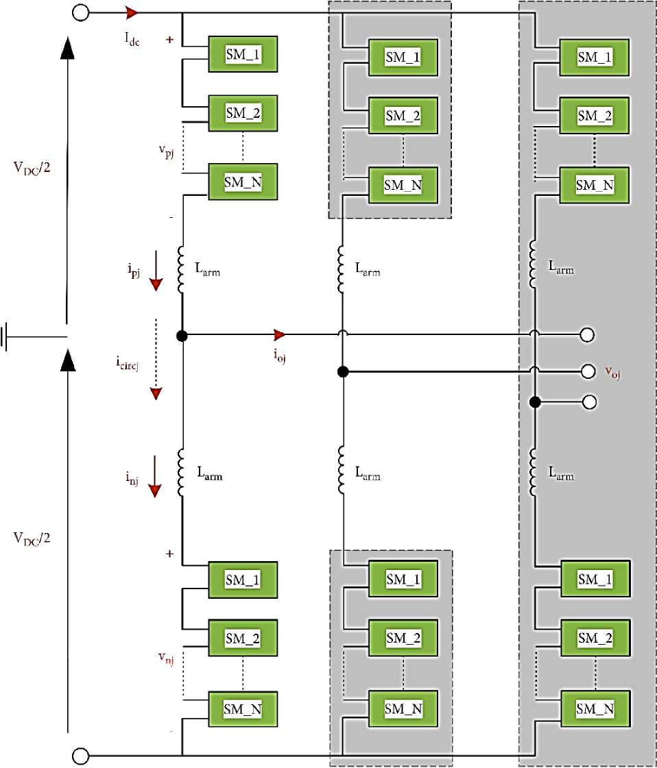
The MMC circuit is highly modular, and can meet the requirements of different power and voltage levels by increasing or decreasing the number of sub-modules connected to the converter, which facilitates the realization of integrated design, shortens the project cycle and saves costs. Different from the traditional VSC topology, although the three-phase bridge arms of the MMC are also connected in parallel, the AC reactor is directly connected in series in the bridge arms, instead of being connected between the converter and the AC system like the traditional VSC. The role of the AC reactor in the MMC is to suppress the interphase circulating current caused by the incomplete instantaneous value of the DC voltage of each phase bridge arm, and at the same time, it can also effectively suppress the inrush current when the DC bus fails and improve the reliability of the system [19–21].
The topology of the three-phase modular multi-level converter is shown in Figure 1. One converter has 6 bridge arms, each bridge arm is formed by a reactor L arm and N sub-modules SM connected in series. The upper and lower bridge arms are combined as a phase unit, as shown in
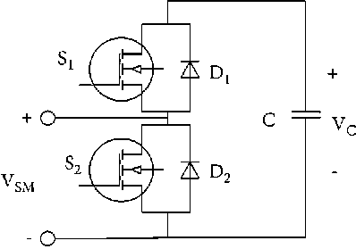
Figure 2, which is a sub-module (SM) topology, S1 and S2 represent IGBTs, D1 and D2 represent anti-parallel diodes, and C represents sub-modules As can be seen from the figure, each sub-module has a connection port for connecting to the main circuit topology in series, and the MMC supports the voltage of the DC bus through the DC-side capacitors of each sub-module. N series-connected identical SMs and an arm inductor are included in each arm as shown in Figure 1. The DC capacitor and two switching components with antiparallel diodes are placed in each SM, which is defined as half-bridge SM (HBSM) and represented in Figure 2 [22, 23].
Upper Arm Phase (Leg)
Lower Arm
(cc) ®
Figure 1. Three-phase circuit configuration of the MMC topology
-
Figure 2. HBSM power cell
Table 1
SWITCHING LOGICS OF HBSM
|
Si |
51 |
'и |
Capacitor |
^SM |
|
1 |
0 |
Positive |
Charging |
Vc |
|
1 |
0 |
Negative |
Discharging |
Vc |
|
0 |
1 |
Positive |
Unchanged |
0 |
|
0 |
1 |
Negative |
Unchanged |
0 |
Conventional NLM Method
Due to the flexibility and ease of implementation of NLM, level control has recently become a popular technique used in modular multilevel converters (MMCs) with a large number of submodules (SMs). Its control idea is relatively simple. Divide the desired modulation voltage by the capacitor voltage of a single sub-module, and then round it as the final input sub-module number, that is, use the superposition of the sub-module voltages to approximate the modulation wave as much as possible, and then obtain the PWM pulses of all sub-modules. Figure 3 shows the basic principle of the C-NLM. Each arm could be controlled separately by using this method. The control scheme of the C-NLM is represented in Figure 4 [24, 25].
In C-NLM, output performance of MMC is more preferable when the number of SMs in the upper and lower arm is more than enough count. Otherwise, when a few SMs are used in the arms for low modulation ratios, no output voltage is obtained on the AC side of MMC. This principle shows that the error of the approximation does not exceed half of the capacitor voltage of the submodule. The MMC using the NLM modulation method can approximate the modulated wave in a large working range, and the harmonic content of the output voltage is very small, but the NLM modulation technique also has some shortcomings, such as high requirements for the balance control of the DC capacitor voltage, dynamic tracking The performance is poor, and the number of switching times is related to the capacitor voltage balance, and the switching loss may be large. And traditional NLM (C-NLM) is mainly adopted by MMC applications with a relatively large number of SMs because it can provide satisfactory output quality; conversely, it provides poor output for
MMCs with a small number of submodules (SMs).
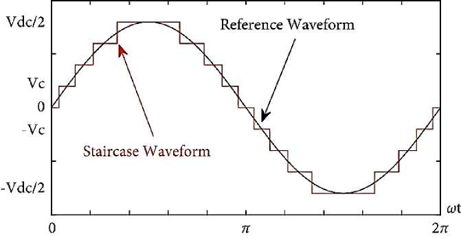
Figure 3. Basic concept of C-NLM
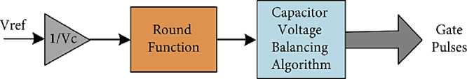
Figure 4. Control structure of C-NLM
The single-phase circuit structure of MMC required for the modulation of phase-a of MMC voltages can be defined as:
is is
given in Figure 5 Mathematical modeling presented in the following formulas. Arm
V u
VDC
-
V 0
- L
di u
V L = VDC + V 0
- L
arm dt di l arm dt
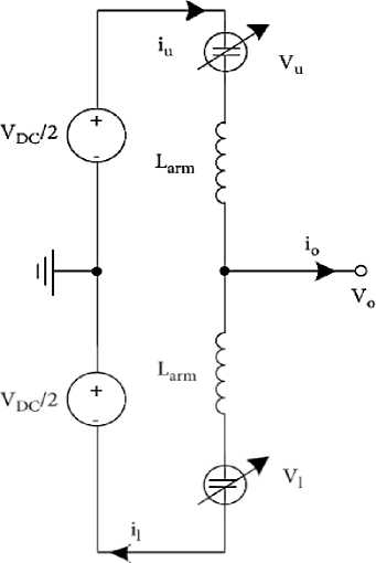
Figure 5. Single-phase equivalent circuit diagram of MMC
Improved NLC methods
The recent level modulation is similar to the staircase wave modulation. The method is simple in principle, easy to implement, and high in efficiency. However, when the number of inverter levels is small, the approximation error is relatively large, and low-order harmonics also appear. Therefore, many scholars have expressed their views one after another. This article summarizes some typical improvement methods. Xiao Hao, Gao Guige, Zeng Xianwen, and Pei Zeyang proposed a new NLC regulation method in a Modified Nearest Level Modulation for Modular Multilevel Converter. By changing the traditional rounding function, the number of output modulation sinusoidal waveform levels is increased, the harmonic content of the output voltage waveform is reduced, and the output waveform quality is improved; the influence of different rounding functions on the output waveform quality is analyzed [26]. However, this experiment only uses two pairs of experimental data for comparison, and the availability of experimental data needs to be considered, and this experiment mainly considers the factors that affect the result of harmonic content and does not adjust all the control objectives at the same time.
In [27], an enhanced level-increased nearest level modulation (eNLM) method is proposed to improve the performance of modular multilevel converter (MMC) with relatively small number of submodules. The eNLM method can almost double the level number of ac output voltage, compared with conventional NLM. Consequently, the ac output voltage quality of the MMC using eNLM is significantly enhanced. The proposed method inherits the advantages of the conventional NLM such as simple implication and low switching loss and avoids the disadvantages of the existing improved NLM method such as increasing in submodule capacitor voltage ripple amplitude and voltage offset, arm inductor voltage peak, complexity in topology, etc. PSCAD/EMTDC simulation results confirmed the effectiveness of the proposed method.
In [28], to further improve the output performance of MMCs containing few SMs, an improved predictive NLC (I-PNLC) method combining NLC and model predictive control (MPC) is proposed, in which the output and circulating currents are regulated by the corresponding predictive references, and the output Voltage is controlled by additional voltage correction. The proposed I-PNLC not only greatly reduces the total harmonic distortion (THD) of the output current and voltage, but also avoids additional complexity in the control system design. In addition to comparing the evaluation of traditional NLC methods, simulation and experimental results are provided to validate the proposed method.
In [29], an improved NLC is proposed, which is able to improve the output quality of MMC with a small amount of SM without degrading the control objective. Unlike previously reported NLC methods, instead of calculating the number of SMs directly from the upper and lower arm voltage references, the difference and the total number of SMs are obtained from the output voltage reference and loop current control, respectively. Therefore, the number of SMs for the upper and lower arms can be obtained by simply solving a system of first-order binary equations. The appropriateness and effectiveness of the proposed improved NLC method are verified by simulation and experimental results of a single-phase MMC system. The basic idea behind the NLC method is to use the upper and lower arm voltage references to generate the number of SMs inserted into the corresponding arms. However, adjusting the number of SMs inserted into the upper and lower arms to maintain control targets may degrade the output voltage quality or average SM capacitor voltage. To address this issue, the proposed modified NLC uses the output voltage and circulating current references to calculate the number of inserted SMs in the upper and lower arms. Compared with previous NLC methods, this method also guarantees the control objective of MMC and improves the output quality.
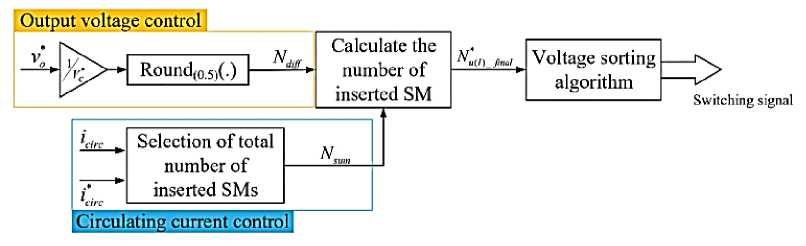
Figure 6 A control chart describing the proposed NLC
In [30] an improved Nearest Level Modulation (NLM) method is proposed to improve the output voltage quality of a modular multilevel converter (MMC) with a small number of submodules and suppress the voltage fluctuations of the submodules. By adding a small offset to the reference signal that alternates at a double fundamental frequency, a small phase shift of the stepchange torque between the upper and lower arm voltages occurs. As a result, there is an odd level difference between the output voltage of the lower arm and the output voltage of the upper arm, and the number of levels of the output voltage can be increased from N+1 to 2N+1, where N is the number of submodules per arm. Using the suggested method, in The total harmonic distortion (THD) of the output voltage is mitigated without increasing the switching frequency of the IGBTs or changing the average voltage of the sub-module capacitors. Furthermore, within a specific power factor angle range, the circulating current can be reduced by choosing an appropriate phase between the fundamental and dual fundamental frequencies.
In [31] an improved Nearest Level Modulation (NLM) method is proposed for MMC, in which the number of levels of the AC output voltage is increased to 2N + 1 (where N is the number of submodules per arm), which is equal to the number of levels of the carrier phase Kind of big. Shifted PWM and improved sub-module unified PWM approach. The number of series is almost doubled, and the height of the steps in the step wave is halved. Therefore, the AC output voltage waveform quality using this method is better than that using the traditional NLM method. In addition, this method retains the implementation of traditional NLM methods. Figure 7 illustrates the principle of the improved NLM method. It is worth noting that the moments of step changing in ustep and ustepare not low switching frequency and simple exactly the same. The level numbers of arm voltages are N + 1, while the level number of output voltage is 2 N + 1. Moreover, the step height of the output voltage is decreases to 0.5Ud. This little difference leads to substantially increased levels.
In [32] a new NLM method is developed that improves the output voltage quality of the MMC topology. The proposed NLM method is based on offset term injection, which is optimally determined according to the best output performance of the MMC. Using a trapezoidal reference signal instead of a sinusoidal reference ensures better output voltage quality and controls the modulation process. Figure 7 shows the working principle of the trapezoidal signal. A trapezoidal waveform can be thought of as an intermediate shape between a square wave and a triangle wave [33]. Figure 8 shows the waveform of the trapezoidal wave. This modulation method is different from other methods. It uses different signal waves for modulation. Several simulation experiments and laboratory experiments have been carried out, and all conceivable influencing factors have been considered.
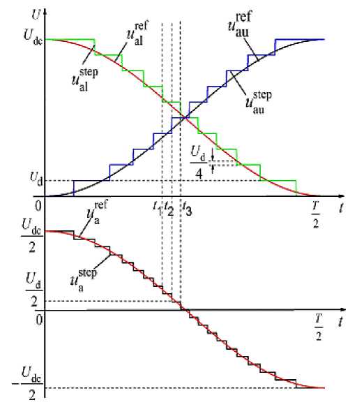
Figure 7. Principles of the modified NLM method.
The authenticity of this experiment is strong. It is worth reference. There are four main parts including rise time (tr), high time (tH), fall time (tf), and low time (tL) in this waveform. While the signal remains at its maximum level (+MI) during tH, it remains at its minimum level (-MI) during tL . Also, the signal increases linearly from the minimum level to the maximum level during tr, whereas it decreases linearly from the maximum level to minimum level during tf.Fundamental period (T) of the trapezoidal signal is formed by the summation of these four parts:
T = tr + tH + tf + tL.
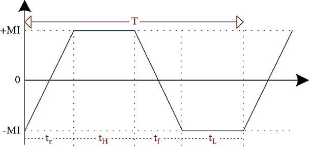
Figure 8. Representation of a trapezoidal signal
Conclusion
The NLM method described above can increase the number of levels of the output voltage and keep the switching frequency unaffected. On the other hand, they bring some difficulties such as increasing capacitor voltage ripple per SM, arm inductance voltage peak and computational complexity. Nowadays, there is no near-perfect modulation method, and there will always be a phenomenon of neglecting the other. This article only summarizes some modulation methods that appear today, and provides a reference for the selection of MMC modulation technology in engineering applications. for further exploration.
References Review on nearest level modulation methods based on MMC
- 倪云林, 辛华龙, & 刘勇. (2009). 我国海上风电的发展与技术现状分析. 能源工程, 4(5).
- 时智勇, 王彩霞, & 李琼慧. (2020). “十四五” 中国海上风电发展关键问题. 中国电力, 53(7), 8-17.
- 黄碧斌, 张运洲, & 王彩霞. (2020). 中国 “十四五” 新能源发展研判及需要关注的问题. 中国电力, 53(1), 1-9.
- 时智勇, 王彩霞, & 李琼慧. (2020). “十四五” 中国海上风电发展关键问题. 中国电力, 53(7), 8-17.
- Breuer, W., Povh, D., Retzmann, D., Teltsch, E., & Lei, X. (2004, October). Role of HVDC and FACTS in future Power Systems. In CIGER Symposium, Shang Hai.
- Dorn, J. (2007). Novel voltage-sourced converters for HVDC and FACTS applications. In Conf. Rec. cigre, OSAKA, 2007.
- Westereweller, T. (2010). Trans bay cable-world's first HVDC system using multilevel voltage-sourced converter. CIGRE Session 2010.
- Clark, H. K., El-Gasseir, M. M., Epp, H. K., & Edris, A. A. (2008, March). The application of segmentation and grid shock absorber concept for reliable power grids. In 2008 12th International Middle-East Power System Conference (pp. 34-38). IEEE. https://doi.org/10.1109/MEPCON.2008.4562303
- Lesnicar, A., & Marquardt, R. (2003, June). An innovative modular multilevel converter topology suitable for a wide power range. In 2003 IEEE Bologna Power Tech Conference Proceedings, (Vol. 3, pp. 6-pp). IEEE. https://doi.org/10.1109/PTC.2003.1304403
- 蒋冠前, 李志勇, 杨慧霞, & 杨静. (2015). 柔性直流输电系统拓扑结构研究综述. 电力 系统保护与控制, 43(15), 145-153.
- 肖晃庆, 徐政, 薛英林, & 唐庚. (2014). 多端柔性直流输电系统的启动控制策略. 高电 压技术, 40(8), 2550-2557.
- 魏晓光 (2006). 汤广福. 基于电压源换流器的高压直流输电系统离散化建模与仿真研 究. 电网技术, 30(20), 34-39.
- 管敏渊 (2013). 基于模块化多电平换流器的直流输电系统控制策略研究. 杭州: 浙江 大学.
- Tang, G., He, Z., Pang, H., Huang, X., & Zhang, X. P. (2015). Basic topology and key devices of the five-terminal DC grid. CSEE Journal of Power and Energy Systems, 1(2), 22-35. https://doi.org/10.17775/CSEEJPES.2015.00016
- Zhang, Y., Adam, G. P., Lim, T. C., Finney, S. J., & Williams, B. W. (2010, October). Voltage source converter in high voltage applications: Multilevel versus two-level converters. In 9th IET International Conference on AC and DC Power Transmission (ACDC 2010) (pp. 1-5). IET. https://doi.org/10.1049/cp.2010.0995
- Wu, D., & Peng, L. (2016). Characteristics of nearest level modulation method with circulating current control for modular multilevel converter. IET Power Electronics, 9(2), 155-164.
- Wang, W., Ma, K., & Cai, X. (2021). Flexible Nearest Level Modulation for Modular Multilevel Converter. IEEE Transactions on Power Electronics, 36(12), 13686-13696. https://doi.org/10.1109/TPEL.2021.3089706
- Li, Z., Wang, P., Zhu, H., Chu, Z., & Li, Y. (2012). An improved pulse width modulation method for chopper-cell-based modular multilevel converters. IEEE Transactions on Power Electronics, 27(8), 3472-3481. https://doi.org/10.1109/TPEL.2012.2187800
- Perez, M. A., Bernet, S., Rodriguez, J., Kouro, S., & Lizana, R. (2014). Circuit topologies, modeling, control schemes, and applications of modular multilevel converters. IEEE transactions on power electronics, 30(1), 4-17. https://doi.org/10.1109/TPEL.2014.2310127
- Debnath, S., Qin, J., Bahrani, B., Saeedifard, M., & Barbosa, P. (2014). Operation, control, and applications of the modular multilevel converter: A review. IEEE transactions on power electronics, 30(1), 37-53. https://doi.org/10.1109/TPEL.2014.2309937
- Meshram, P. M., & Borghate, V. B. (2014). A simplified nearest level control (NLC) voltage balancing method for modular multilevel converter (MMC). IEEE Transactions on Power Electronics, 30(1), 450-462. https://doi.org/10.1109/TPEL.2014.2317705
- Rodrigues, S., Papadopoulos, A., Kontos, E., Todorcevic, T., & Bauer, P. (2016). Steadystate loss model of half-bridge modular multilevel converters. IEEE Transactions on Industry Applications, 52(3), 2415-2425. https://doi.org/10.1109/TIA.2016.2519510
- Elserougi, A. A., Massoud, A. M., & Ahmed, S. (2017). Arrester-less DC fault current limiter based on pre-charged external capacitors for half-bridge modular multilevel converters. IET Generation, Transmission & Distribution, 11(1), 93-101.
- Li, R., Fletcher, J. E., & Williams, B. W. (2016). Influence of third harmonic injection on modular multilevel converter-based high-voltage direct current transmission systems. IET Generation, Transmission & Distribution, 10(11), 2764-2770.
- Zhou, W., Dong, Y., Yang, H., Li, W., He, X., Hu, J., & Yuan, X. (2016). Common-mode voltage injection-based nearest level modulation with loss reduction for modular multilevel converters. IET Renewable Power Generation, 10(6), 798-806.
- 肖浩, 高桂革 (2015). 曾宪文, 等. 改进的最近电平逼近调制策略在模块化多电平变流 器中的应用. 上海电机学院学报, 18(2), 70-76.
- Si, G., Zhu, J., Lei, Y., Jia, L., & Zhang, Y. (2019). An enhanced level‐increased nearest level modulation for modular multilevel converter. International Transactions on Electrical Energy Systems, 29(1), e2669. https://doi.org/10.1002/etep.2669
- Nguyen, M. H., & Kwak, S. (2020). Predictive nearest-level control algorithm for modular multilevel converters with reduced harmonic distortion. IEEE Access, 9, 4769-4783. https://doi.org/10.1109/ACCESS.2020.3048156
- Nguyen, M. H., & Kwak, S. (2020). Nearest-level control method with improved output quality for modular multilevel converters. IEEE Access, 8, 110237-110250. https://doi.org/10.1109/ACCESS.2020.3001587
- Lin, L., Lin, Y., He, Z., Chen, Y., Hu, J., & Li, W. (2016). Improved nearest-level modulation for a modular multilevel converter with a lower submodule number. IEEE Transactions on Power Electronics, 31(8), 5369-5377. https://doi.org/10.1109/TPEL.2016.2521059
- Hu, P., & Jiang, D. (2014). A level-increased nearest level modulation method for modular multilevel converters. IEEE Transactions on Power Electronics, 30(4), 1836-1842. https://doi.org/10.1109/TPEL.2014.2325875
- Kurtoğlu, M., & Vural, A. M. (2022). A Novel Nearest Level Modulation Method with Increased Output Voltage Quality for Modular Multilevel Converter Topology. International Transactions on Electrical Energy Systems, 2022. https://doi.org/10.1155/2022/2169357
- Sotorrio-Ruiz, P. J., Sanchez-Pacheco, F. J., Perez-Hidalgo, F. M., & Heredia-Larrubia, J.R. (2017). Modulation of a trapezoidal signal: improving signal quality and reducing costs in power inverters. IET Power Electronics, 10(5), 568-576.
