Sectorized Hamming Concentric Circular Arrays for Stratospheric Platforms Cellular Design

Author: Yasser Albagory
Journal: International Journal of Computer Network and Information Security(IJCNIS) @ijcnis
Article in issue: 9 vol.5, 2013.
Free access
Recently, stratospheric platform communications system (SPs) has gained great interest due to its superior performance compared to conventional communications systems. This paper addresses one of the major performance keys in SPs which is the cellular design based on adaptive concentric circular arrays (CCA). The proposed design technique aims to provide circular cells at any elevation angle to overcome the cell flattening and broadening which result in ellipsoidal cell shape. The cell footprint is controlled by adjusting the beamwidths which can be established by sectorizing the CCA and tapering the current amplitudes of the effective sectors by Hamming function while the others are muted and the resulted array is called Sectorized Hamming tapered CCA (SHTCCA). In this array, each sector has an angular width of 90o and some and two opposite sectors are fully fed while the others has less number of quarter-circular arrays. The tapering of the active sectors results in lower sidelobe levels which is a paramount improvement for the cellular systems. In addition, the SHTCCA is analyzed and optimized to provide the desired beamwidths at any elevation angle that are needed to design circular cell footprint.
Stratospheric platforms, concentric ring arrays, Hamming function, cellular communications
Short address: https://sciup.org/15011224
IDR: 15011224
Text of the scientific article Sectorized Hamming Concentric Circular Arrays for Stratospheric Platforms Cellular Design
Recently, an innovative communication system based on Stratospheric Platforms (SPs) has gained attention as it preserves many advantages of the conventional terrestrial and satellite systems and provide special advantages of their own [1-3]. SPs are stations made of airships or airplanes positioned at altitudes 17–22 km high and have the potential to deliver communications services cost effectively. A single SP can replace a large number of terrestrial base stations and their backhaul infrastructure. The high-altitude property of SPs indicates better radio coverage and line-of-sight communications as in satellite systems but at lower propagation delays which are comparable to that of terrestrial systems. It may be used in other applications such as disaster monitoring and mitigation [4] and global positioning [5].
One of the most important parameters that affect the HAP system performance is the type of antennas used to provide the radio coverage especially for the cellular systems. The antenna controls the shape and design of the ground coverage cells. The multi-beam horn (MBH) antenna and antenna arrays were developed for highspeed transmission at 48/47-GHz in [6], while in [7], a low sidelobe level and asymmetric beam antenna was developed using lens antenna to provide almost circular footprint especially at lower elevation angles.
In [8], the concentric circular array (CCA) is examined to provide an improved HAP cellular coverage performance where it has many advantages such as independent azimuth beamforming and lower sidelobe levels.
Adaptive beamforming techniques have gained a great interest as it introduces a valuable improvement in the quality of service and system capacity [9]. In the recent communications technologies, the adaptive arrays will be an essential part of the system and the only impeding force may be the complexity of calculations which requires super fast processors with large memory. The problem exaggerates in the case of two dimensional arrays and especially at large number of elements. For communications systems based on SPs, we need a two dimensional beamforming technique which implies that a form of two-dimensional arrays or concentric circular arrays may be used which both will contain a large number of elements. Therefore, adaptive techniques are not practically in these applications and direct design techniques without extensive searching or learning must be applied in this case. An example of known fast beamforming techniques is the phased arrays in which a desired pattern can be obtained by direct calculations of the weights [9]. Another improvement in the phased arrays technique can be implemented through the amplitude tapering which reduces the sidelobe levels at the expense of some increase in both beamwidth and number of elements [10]. On the other hand, the coverage from SPs faces some difficulties in the cellular design where the layout cells do not have the same shape if they have the same beamwidths but directed towards different elevation angles. The cells will be broadening and become ellipsoidal shaped especially at lower elevation angles and a technique should be applied to preserve its circular shape. An optimization for the circular cell design was made in [7] but suffers from the inflexibility where a constant cell was obtained without the ability to modify its shape. Therefore in this paper, a new beamforming technique is proposed that can produce a ground circular footprint that is independent on the elevation angles and projection. This technique is based on sectorizing a concentric circular array with a certain angle to control the beamwidths and compensate for the ellipsoidal shape of the HAP cell at lower elevation angles. The paper is arranged as follows; in Section 2 we introduce the HAP cell parameters showing the variation of the cell axes with the elevation angle. In Section3, the array geometry and its related beamforming equations are drawn and Section4 introduces the new beamforming technique and analyses the resulted cell footprint. Section 5 will discuss some of the results obtained and finally section 6 concludes the paper.
-
II. HAP CELL FOOTPRINT
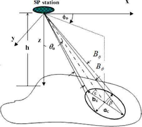
As shown in Fig. 1(a), the 3 dB contour of a beam directed towards (60, 0O ) from SP station. The direction of the beam and its beamwidths form the basic parameters that affect its footprint. Relating the cell location with the elevation angle is practically very important, therefore, it is advantageous to express the coverage area in terms of the beam pointing directions or elevation angles and depicts the corresponding central distance in km away from the subplatform point. Assuming that the elevation angle at the cell center is denoted by £ , it can be related by the beam pointing direction, 60 , by the following approximate relation as shown in Fig. 1(a) :
£ =90 - 6 o (1)
Consider the contours of the pointing angles as shown in Fig. 2 where it indicates the ground distance from the subplatform point at certain beam directions. It also shows the elevation angle contours at these pointing directions, which is an important parameter in the HAP radio coverage design from HAPs. In most HAPs communications applications, the minimum elevation angle of 15 degrees is acceptable to avoid excessive scattering at lower elevation angles. The radius of coverage at this angle will be approximately 75 km.
To explain the effects of the projection on the footprint we assume that the earth surface is considered flat especially at higher elevation angles and thus the cell axes are given by:
bc = R (sin-1 ((1 + -^ sin (90 - £ + у)) -sin-1((1+ ^ sin (90 -£-^-Be) (2)
and ac = 2h sec(90 - e) tan (y) (3)
Where R is the earth’s radius which is about 6375 km, h is the platform altitude in km and B e and B ^ are the beamwidths in 6 and 0 directions respectively. The last equations are written in terms of the elevation angle to discuss its effect on the resulted cell footprint. Fig. 3 describes the variation of the cell axes with £ assuming fixed beam cross section of 10 degrees (i.e B e = B 0 = 10 degrees). The decrease in £ will actually increase both the cell axes but bc increases greater than ac which results in an oval or ellipsoidal footprints. The ellipse eccentricity increases as the elevation angle decreases and the overall cellular layout will have irregular cells. The problem exaggerates as we use antenna arrays in forming the cells due to the decreased effective area of the array seen at the lower elevation angles. This problem will be managed in the coming sections where the beam shape is refined to have lower sidelobe levels and is tailored in the initial pattern so that after projection gives the desired circular footprint.
(a)
Figure 1 : Footprint of a HAP cell
The last two equations are very important in determining the condition at which we can obtain a circular footprint even if the elevation angle is very low. To obtain a circular footprint at certain elevation angle, the resulted cell axes must be equal and this can be obtained only when we start with a value of a c that is greater than b c or with a beam cross section of B 0 greater than Be . The exact values can be obtained when equating (2) with (3) and solving for the two values of the beamwidths.
In the following section, the antenna array used to optimize the cell for circular coverage will be introduced and analyzed.
-
III. BEAMFORMING USING HAMMING TAPERED CONCENTRIC CIRCULAR ARRAYS (HTCCA)
Concentric circular antenna array (CCA) contains a number of concentric circular rings of different radii and number of elements as shown in Fig. 4. It has several advantages including the flexibility in array pattern synthesis and design both in narrowband and broadband beamforming applications [11].
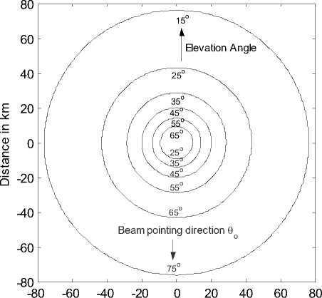
Distance in km
Figure 2: Ground contours of beam pointing directions and elevation angles for a HAP at 20 km high.
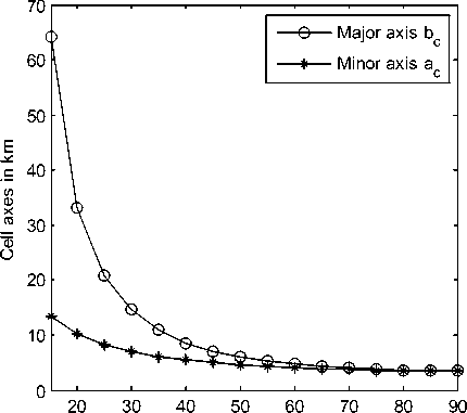
Elevation angle in degrees
Figure 3 : Variation of SP cell axes with the elevation angle formed by constant beamwidth antenna.
CCA is also favored in direction of arrival (DOA) applications since it provides almost invariant azimuth angle coverage. In addition, the frequency invariant characteristics of CCA have been proved for wideband applications. There are numerous design techniques for that array to fit the required power pattern characteristics; for example changing the separation between rings and the number of elements of each ring and/or the feeding currents' amplitudes and phases. In this section, the interelement separation is kept almost half of the wavelength to avoid the appearance of the grating lobes, which exist at separations larger than this value. If this spacing is smaller than half of the wavelength, we have a wider beamwidth, which reduces the array efficiency. Also the amplitudes of the feeding currents are kept equal as in phased arrays to simplify the design and only the phases are determined to form the mainlobe in the desired direction. A main problem occurs in this array configuration when the number of the rings is small which results in higher sidelobe levels and in turn weaken the array performance. This increase in sidelobe levels may be serious in many applications; therefore an antenna element is proposed to be inserted at the center of the array which may results in sidelobe reduction if carefully fed. Therefore in this section, the uniform halfwavelength CCA (UCCA) is analyzed showing the effects of the array geometry on its performance and the central element feeding case is also discussed.
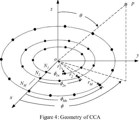
The arrangement of elements in CCA contains multiple concentric circular rings which differ in radius and number of elements and this gives arise to different radiation patterns. Fig. 4 shows the configuration of CCA in which there are M concentric circular rings. The mth ring has a radius r and a number of elements N where mm m = 1, 2,..., M . Assuming that the elements are uniformly spaced within the ring so it has an element angular separation given by:
^ m
2 л
N m
and the elements in this ring are therefore located with an azimuth angle measured from the x-axis given by:
0 mn = n^ m , П = 1,2,™, Nm (5)
We can deduce an expression for the array steering matrix by first defining the array steering vector for a single ring and extending the analysis for the whole array. The array steering vector for the mth ring will be:
Sm(в 0) = [e7'kr m s i n ecos(0-0 mi ) e;kr m sin 6cos(0-0 m2 ) ™ g Vkf m sin 6 cos ( 0-0 m*m )]T (6)
Where к = — and the array steering matrix can be formulated as:
In most cases, the maximum number of elements will be in the outermost ring, where it has NM elements, therefore it will determine the steering matrix size that in this case will be N,, x M and in this case, and each M preceding column must be appended by zeros (zero padding).
We can control the radiation pattern of the array by controlling the magnitudes and phases of the exciting currents. Therefore, the array factor may be determined from the fo llo wing equation:
G (0, 0) = SUM [Wh Acca (0 , 0)] (8)
where the SUM operator is the summation of all elements in the resulted matrix WhAcca (0, 0), H is the complex conjugate transpose or Hermitian operator and W is the weight matrix that controls the amplitudes and phases of the input currents. The main lobe can be formed towards the pointing direction ( 0O , 0O ) by making the weight matrix to be equal to the array steering matrix at this direction or:
w(0o, 0O ) = [P1S1(0O , 0O )> P-S2(0O , 0O )I — , pmSm(0O, 0o ), — ,pMSM (0o, 0o)] (9)
where pm is the mth circular array amplitude coefficient and is used for tapered CCA (TCCA).
The Hamming window used for filter applications can be modified and used to determine the values of pm , therefore:
„ — „ „ . , f-(m-M-2)\ . „ _ .
pm = 0.54 + 0.46 cos ^—J, m = 1,2,..., M (10)
Fig. 5 depicts the variation of the Hamming window for 10 TCCA and Fig. 6 displays the radiation pattern of the same array where the sidelobe level is reduced to about -30 dB.
-
IV. CELL AXES CONTROL BY THE SECTORED HTCCA
According to (2) and (3), the cell axes increases with the decrease in the elevation angle with a more increase in the radial major axis bc . This effect can be mitigated by making the beam to be asymmetric from the beginning and at the specified elevation angle or beam direction will circle the ellipse again. Therefore in this section, we propose a weighting function that sectorizes the HTCCA so that it can control the beamwidth in the desired direction.
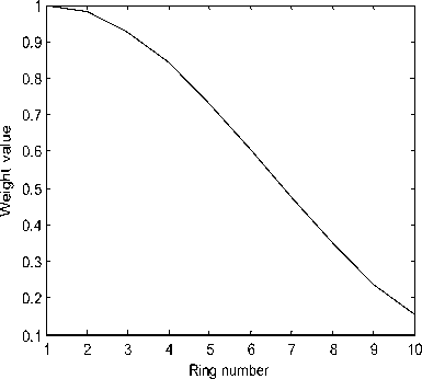
Figure 5 : Hamming window variation with the ring number in 10 rings UCCA.
The proposed function will depend on the beam direction ( 00 , 0O ) and utilizes a certain number of sectored circular arrays to get the desired beam pattern. We can start sectorization of the CCAs from the innermost ring but actually to reduce the sidelobe levels and beamwidth we divide the HTCCA into two sub HTCCAs, the first is a complete HTCCA with a number of CCAs equal to ms and the other is a sectorized HTCCA with number of CCAs equal to M — ms .
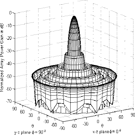
Figure 6: Normalized power pattern for Hamming tapered UCCA of 10 rings.
The individual CCAs are therefore weighted by:
„ - . . „ . , (-(m-M- 2)\ . _ ,...
p m = 0.54 + 0.46 cos ^—j^—J, m = 1,2, .„, ms (11)
and for m = ms + 1, ms + 2, ., M
-(m-M--)^
p m = 0.54 + 0.46 cos ( M + 1 J, (12)
where
-<®.„<1 „, 51 >9т> 31 4 тп 4 4 тп 4
Otherwise рт = 0.
From the definition of рт , the CCAs are controlled by both the sectorizing function and the value of ms. This will give us a more space of control to find the required footprint at the desired elevation angle or beam direction. Fig. 7 displays an unsectorized CCA where ms = M while Fig. 8 shows the CCA configuration for M = 10, N 1 = 3, and ms = 5 where the vertical axis is aligned towards the radial axis of the cell, bc and rotated if the cell has rotated or changes its azimuth direction.
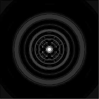
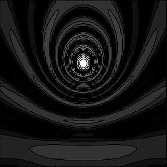
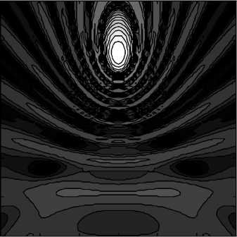
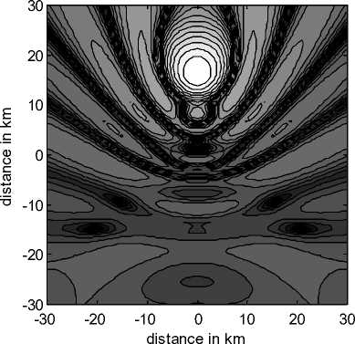
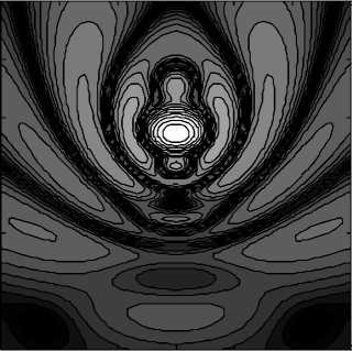
The footprint of an SP cell will be examined for a two cases; that are for the unsectorized and optimum sectorized HTCCA. Fig. 9(a)-(c) display the footprint of a cell at three different elevation angles where the footprint become ellipsoidal as expected from (2) and (3)
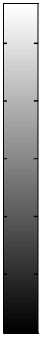
On the other hand, Fig. 10(a)-(c) optimizes the cell shape to provide circular shape at an elevation angle of 45o where the beams are constructed by SHTCCA of the same parameters as in Fig. 8. The first one is formed at £ = 0 o and the footprint is an ellipse due to the sectorization of the TCCA. For £ = 20 o the ellipsoidal cell became of less eccentricity and near circular and finally at £ = 45 o the cell became almost circular and the effect of array projection and spherical earth is equalized. Therefore, a regular cellular system can be obtained by adjusting the array parameters.

S
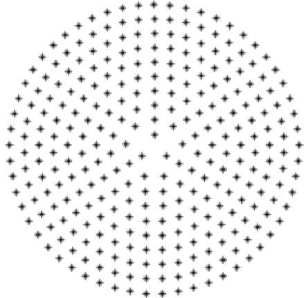
Figure 7: Unsectorized CCA, m s = M
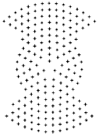
Figure 8: Sectorized CCA at m s = 5
-30 -20 -10 0 10 20 30
distance in km
-10
-20
-30
9 (d)
S
-10
-20
-30 -20 -10 0 10 20 30
distance in km
-30
9 (b)
-10
-20
-30
-40
-50
-60
-10
-20
-30
-40
-50

-60
distance in km distance in km distance in km
-10
-20
-30
-30 -20 -10 0 10 20 30
distance in km
9 (c)
-10
-20
-30
-40
-50
-60
-10
-20
-30
-40
-50
-60
9: The normalized power distribution of a cell that is not
optimized where:
(a) The cell footprint at 0 elevation angle, (b) The cell footprint at 20 elevation angle and (c) The cell footprint at 45 elevation angle.
-10
-20
-30
-30 -20 -10 0 10 20 30

-10
-20
-30
-40
-50
-60
10 (c)
Figure 10: The normalized power distribution of a cell optimized to provide almost circular cell footprint where:
-
(a) The cell footprint at 0 elevation angle,
-
(b) The cell footprint at 20 elevation angle and
-
(c) The cell footprint at 45 elevation angle.
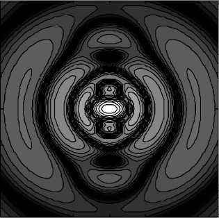
Figure 11: Variation of the optimum beamwidth, B 0 with the elevation angle at different values of B 6
-
- 10
-
- 20
-
- 30
distance in km
10 (a)
-30 -20 -10 0 10 20 30
distance in km
10 (b)
-10
-20
-30
-40
-50

The HSTCCA is optimized to find the required values of B 0 with the elevation angle at different values of B 6 as shown in Fig. 11. The two beamwidths are equal at elevation angle of 90 o that is the subplatform point while the value of B 0 must be increased at other lower values of the elevation angle to compensate the elongation in the major axis by increasing the minor axis and the final result is having an equal cell axis at the desired elevation angle.
The optimization of the HSTCCA can be also done but with the cell radial distance as another parameter used in the cellular design as shown in Fig. 12, where the relation between this distance with the elevation angle is given by:
R c = h tan(6>0 )
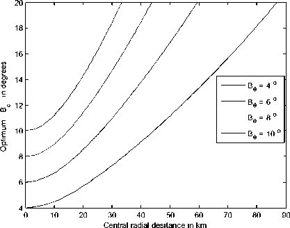
Figure 12: Variation of the optimum beamwidth, B ^ , with the cell radial distance at different values of B 6
-
VII. CONCLUSIONS
In this paper, a proposed technique has been introduced to overcome the flattening and broadening of the cells especially at lower elevation angles at a lower cost of processing time. The CCA has been optimized to generate asymmetric beams that provide circular cell footprint at the desired elevation angles. The technique is based on sectorizing the CCA into four symmetric sectors with 90 degrees width and of different lengths where some quarters in the individual circular arrays for the same sector is muted which the inner ones are fed with a Hamming tapering function. This tapering has provided smaller sidelobe level which is an important improvement factor for the cellular systems. The optimization of the sectorized Hamming tapered CCA (SHTCCA) has defined the required beamwidths for designing the circular footprint at the desired elevation angles.
References Sectorized Hamming Concentric Circular Arrays for Stratospheric Platforms Cellular Design
- A. Mohammed, A. Mehmood, F. Pavlidou and M. Mohorcic "The Role of High-Altitude Platforms (HAPs) in the Wireless Global Connectivity", Proceedings of the IEEE, Vol. 99, No. 11, pp. 1939 – 1953, Nov. 2011.
- J. Kim, D. Lee, J. Ahn and B. Ku, "Is HAPS Viable for the Next-Generation Telecommunication Platforms in Koria", EURASIP Journal on Wireless Communications and Networking, Vol. 2008, doi: 1155/2008/596383, 2008. doi>10.1155/2008/596383
- S. Karapantazis and F. Pavlidou "Broadband Communications via High-Altitude Platforms: A Survey", IEEE Communications Surveys & Tutorials, First Quarter 2005, pp. 1-31, 2005.
- P. Pace and G. Aloi "Disaster Monitoring and Mitigation using Aerospace Technologies and Integrated Telecommunication Networks", IEEE Aeropspace and Electronic Systems Magazine, Vol. 23, No. 4, pp. 3-9, April 2008. D O I: 10.1109/MAES.2008.4493436
- L. Bocca, G Amendola and G. Di Massa "Low Multipath Antennas for GNSS-based Attitude determination Systems Applied to High Altitude Platforms", GPS Solutions, Vol. 12, No. 3, pp. 163-171, July 2008.
- J. Thornton, D.A.J. Pearce, D. Grace, M. Oodo, K. Katzis and T.C. Tozer, "Effect of Antenna Beam Pattern and Layout on Cellular Performance in High Altitude Platform Communications", Wireless Personal Communications, Vol. 35, pp. 35-51, 2005.
- J. Thornton, "A Low Sidelobe Asymmetric Beam Antenna for High Altitude Platform Communications", IEEE Microwave and Wireless Components Letters, Vol. 14, No. 2, pp. 59-61, February 2004.
- Moawad Dessouky, Hamdy Sharshar, Yasser Albagory "Improving The Cellular Coverage from A High Altitude Platform by Novel Tapered Beamforming Technique," Journal of Electromagnetic Waves and Applications, JEMWA, Vol.21, No.13, pp. 1721 –1731, 2007.
- L. Godara, "Application of antenna arrays to mobile communications, Part II: beam-forming and direction of arrival considerations," Proceeding of IEEE, vol. 85, no. 8, pp. 1195-1245, Aug. 1997.
- Mostafa Nofal, Sultan Aljahdali and Yasser Albagory, "Tapered Beamforming for Concentric Ring Arrays", AEU International Journal of Electronics and Communications, Vol. 67, No. 1, pp. 58-63, 2013.
- S. C. Chan, and H. H. Chen, "Uniform Concentric Circular Arrays with Frequency-Invariant Characteristics—Theory, Design, Adaptive Beamforming and DOA Estimation", IEEE Transactions on Signal Processing, Vol. 55, No. 1, pp. 165-177, January 2007.
