Security evaluation of cellular networks handover techniques

Author: Vincent Omollo Nyangaresi, Silvance O. Abeka, Anthony Rodgrigues
Journal: International Journal of Computer Network and Information Security @ijcnis
Article in issue: 5 vol.10, 2018.
Free access
This paper examined the handovers in cellular networks from both functional and informational security point of view. The aim was to find out if the security goals of confidentiality, integrity and availability (CIA) are preserved during handovers. Whereas functional security is concerned with the proper operation of the handover procedures, informational security deals with confidentiality and integrity of the handover process. The global system for mobile communication provides data and voice communication services by partitioning coverage areas into hexagonal cells. Since mobility is a prime feature of cellular networks, handovers become significant for the continuity of ongoing calls. However, if these handovers are not handled carefully, session hijacking, masquerading and denial of service can be launched by transmitting at the correct timeslot and frequency. The results of the security investigation of the current handover techniques, methods, procedures, schemes and criteria revealed that the CIA triad was not assured during the handover period. The root cause of these attacks is high latency between handover request and handover execution. To address these shortcomings, this paper proposes an authenticated multi-factor neuro fuzzy handover protocol with low latency for both homogenous and heterogeneous cellular environments.
Denial of service, GSM, handovers, masquerading, neuro-fuzzy, session hijacking
Short address: https://sciup.org/15015602
IDR: 15015602 | DOI: 10.5815/ijcnis.2018.05.06
Text of the scientific article Security evaluation of cellular networks handover techniques
Published Online May 2018 in MECS
In a global system for mobile communication (GSM) environment, the coverage area is split into hexagonal regions called cells, with each cell being served by a base transceiver station (BTS). A group of BTS are managed by the base station controller (BSC), which are in turn controlled the mobile switching center (MSC). The users with their communication gadgets such as smart phones and tablets move from one place to another [1].
In the course of these movements, they may cross the cell boundary while communicating and signal levels from their BTS becomes weaker compared with those from the neighbouring BTS. In addition, since each BTS has a limited number of channels to assign to the users for reception and transmission of their data and voice, it is possible for the number of mobile users to become too large that a given BTS is overwhelmed. In both scenarios, handovers become imminent so that the user conversations can take place seamlessly without interruption. In [2], it is pointed out that if the handover procedures are not handled very fast, then the ongoing calls can be terminated, in which case it becomes a dropped call. In cases where the BTS is overwhelmed with user traffic and handover to less congested BTS is not efficient or fails, the entire system can breakdown, affecting all the users within that cell. Both BTS breakdown and dropped calls constitute denial of service to the legitimate users. This is a direct compromise of availability, which is one of the key elements in the CIA triad. High call drop probability deteriorates the network quality of service (QOS) and some users may opt to shift network operators.
-
II. Related Work
As [3] discuss during handovers in 2G, 3G and 4G, the handover request is not authenticated and the user equipment (UE) measurements reports are not encrypted. The reasons for this are a trade-off between performance, availability and functionality. In [4], it was noted that during handover between long term evolution (LTE) and Universal Mobile Telecommunications System (UMTS) networks, the use of internet protocol security (IPSec) is not obligatory. This means that backhauling traffic lacks protection hence some security properties can be easily compromised. As a result, mobile user’s traffic and network’s UE’s are exposed to attacks.
A number of researchers have therefore sought to investigate how authentication can be introduced during the handover process. In [5], a wireless mesh network fast handover authentication technique based on tickets is proposed. One of the challenges of this handover authentication is that sensitive information including time and date of expiration is exchanged in plaintext. In addition, this approach involved the usage of high-quality tamper-proof devices that limits its applicability. Moreover, ticketing can be confusing in situations where the mesh access points within the network are arranged in a sophisticated manner, in which case it might be an uphill task to determine where the UE will next move to. For the case of fourth generation long term evolution (4G LTE) X2 handovers, the scheme lacks backward security and is vulnerable to attacks. As such, [4] proposed an improved group key security in order to guard against malicious attacks during handovers. However as [6], explain, group key authentication may be counterproductive when one or more of the access points in the group turns out to be malicious.
In their paper, [7] noted that in cellular networks, authentication occurs before any location update or call set up can be permitted into the network. In ideal situations, the authentication process takes 0.5 seconds. The accepted time interval between handover command and handover execution is 0.5 - 1.5 seconds. This means that, if the UE is to authenticate itself to the target BTS during handovers, then the authentication process will be a bottleneck since it may introduce further delays, leading to the dropping of an ongoing call. As such, many cellular networks do not perform any authentication during handovers.
As [8] discusses, this exposes the cellular network to a number of attacks, including eavesdropping, impersonation of the network, impersonation of a user and man-in-the-middle. In eavesdropping attack, an intruder is able to listen on the transmitted messages. This is occasioned by weak encryption, weak or no authentication of messages being passed over the radio interface. In network impersonation, an intruder sends bogus messages to the target UE, by tricking it to believe it is coming from a legitimate network. This is facilitated by lack of mutual authentication between the GSM network and the UE. On the other hand, user impersonation an adversary transmits fake messages to the cellular network by falsifying that these messages are from the target UE. Once again, this is accelerated when the UE and the cellular network do not authenticate each other. Further, man-in-the-middle (MITM) attack in which an impostor is positioned between authentic network and the target UE is also feasible when the UE and the network fail to validate each other. Here, the aim is to alter, erase, spoof, re-order or reply to the communication taking place between the cellular network and the UE.
In addition, the handover is now open to masquerading attack, where an intruder assumes the identity of the UE that has requested handover to the target BTS [7]. For this to be successful, the intruder must transmit at the appropriate time slot and frequency. This represents a session hijacking attack, during which the attacker equipped with correct data encryption keys can insert bogus data into the communication channel, hence compromising integrity. The receiver can reply to this bogus message, believing that it was sent by the UE requesting handover. In this case, confidentiality of the communication process would have been tampered with. Effectively, all the CIA triad goals have been compromised.
The aim of this paper was then to scrutinize the current handovers, understanding their weaknesses and based on these shortcomings, propose a multi-factor authenticated handover protocol based on the concept of neuro-fuzzy in order shorten the handover latency while at the same time confirming the identity of the handed-over mobile UEs.
-
III. Cellular Handovers
Mobility is a key feature of the GSM cellular network and as such, a lot of research has been carried out in as far as handovers are concerned. According to, [9] there are four types of handovers: intra-system, intra-frequency, inter-frequency and inter-system handover. However, [10] explain that there are two ways of grouping handovers: horizontal and vertical handovers. In horizontal handover, an ongoing call is transferred from one cell to another cell employing the same access technology. An example of this is a GSM to GSM handover or UMTS to UMTS handover. For the case of vertical handover, an ongoing call is shifted between cells using disparate access technology [11]. An illustration of this is a handover between GSM and UMTS.
In his study, [12] classifies handovers as follows: Intra-cell (Intra BTS) Handover, Inter-cell/ Intra BSC Handover, Inter BSC/ Intra MSC Handover and Inter MSC Handovers. The first handover type occurs when a call is transferred between channels that belong to the same cell while the second type happens when calls are switched between cells that fall under one BSC. On the other hand, the third handover occurs between cells belonging to different BSCs but under the management of the same MSC while the fourth type of handover happens when calls are routed to cells under the control of disparate MSCs.
Moreover, according to [13], handovers are of three categories namely hard, soft and softer handovers. The hard handover is a break before make cell or slot switching while the soft handover is a make before break kind of call transfer. On its part, a softer handover occurs when a call is transferred between two neighboring sectors of the same BTS.
A study by [1] described handovers as being Intra-cell, Inter-cell, Inter-BSC, or Inter-MSC handovers. While intra-cell handovers transfers calls in order to improve on carrier frequency, inter-cell handovers occurs to maintain the stability of a call. On the other hand, inter-BSC and inter-MSC handovers involve more than one BSC and MSC respectively.
A review of the various handover types described above has revealed that these handovers categorization is based on few parameters, mostly on the type of network component involved in the handover process (BTS, BSC or MSC) or number of cells involved in the handover process (intra-cell and inter-cell). There is need to include more criteria for the classification process so as to describe the handover process in finer details, that may help understand the shortcomings of using these criteria in the handover process.
-
IV. Handover Nomenclature
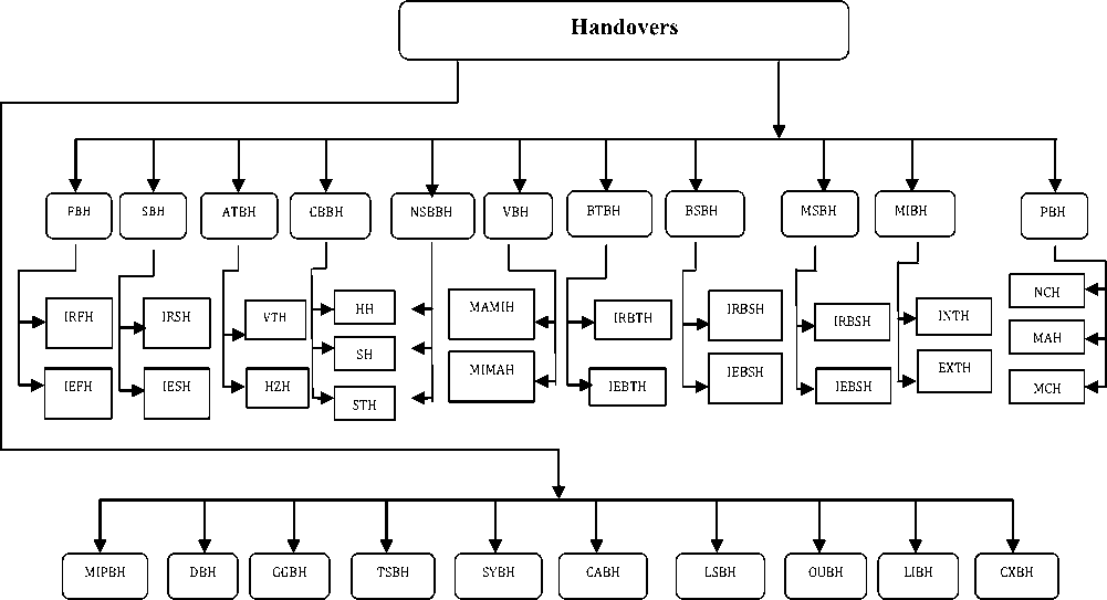
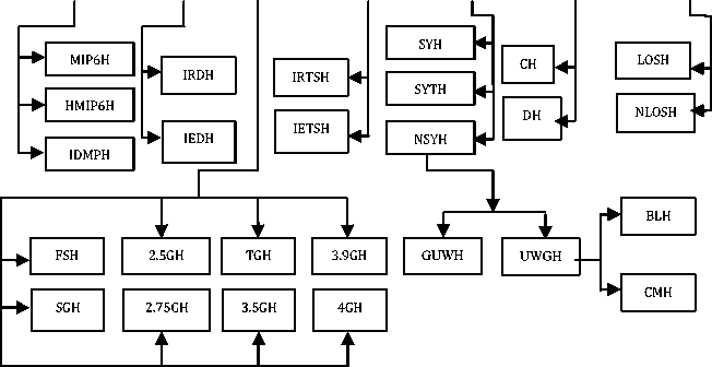
This paper proposes twenty one parameters to act as basis for the handover process. These parameters include frequency (Frequency - Based Handover - FBH), network systems (Systems - Based Handover - SBH), access technology (Access Technology - Based Handover -ATBH), call behavior (Call Behavior - Based Handover -CBBH), number of simultaneous BTS involved in handover (Number of Simultaneous BTS - Based
LEGEND
|
FBH : Frequency Based Handover SBH : Systems Based Handover ATBH : Access Technology Based Handover CBBH : Call Behaviour Based Handover NSBBH : Number of Simultaneous BTS Based Handover VBH : Velocity Based Handover BTBH : BTS Based Handover BSBH : BSC Based Handover MSBH : MSC Based Handover MIBH : MSC Involvement Based Handover PBH : Protocol Based Handover MIPBH : Mobile IP Based Handover DBH : Domain Based Handover GGBH : GSM Generations Based Handover TSBH : Time-Slot Based Handover SYBH : Synchronization Based Handover CABH : Coverage Area Based Handover LSBH : Line Of Sight Based Handover OUBH : Overlay-Underlay Based Handover LIBH : Location Information Based Handover CXBH : Cell Crossings Based Handover IRFH : Intra-Frequency Handover IEFH : Inter-Frequency Handover IRSH : Intra-System Handover IESH : Inter-System Handover VTH : Vertical Handover |
HZH : Horizontal Handover HH : Hard Handover SH : Soft Handover STH : Softer Handover MAMIH : Macro-to-Micro Cell Handover MIMAH : Micro-to- Macro Cell Handover IRBTH : Intra-BTS Handover IEBTH : Inter-BTS Handover IRBSH : Intra-BSC Handover IEBSH : Inter-BSC Handover IRMSH : Intra-MSC Handover IEMSH : Inter-MSC Handover INTH : Internal Handover NCH : Network-Controlled Handover MAH : Mobile-Assisted Handover MCH : Mobile-Controlled Handover MIP6H : Mobile IPv6 Handover HMIP6H : Hierarchical Mobile IPv6 Handover IDMPH : Intra-Domain Mobility Management Protocol Handover IRDH : Intra-Domain Handover IEDH : Inter-Domain Handover FGH : First Generation Handover SGH : Second Generation Handover 2.5GH : 2.5 Generation Handover 2.75GH : 2.75 Generation Handover |
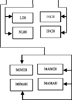
TGH : Third Generation Handover 3.5GH : 3.5 Generation Handover 4GH : 4th Generation Handover IRTSH : Intra-Time Slot Handover IETSH : Inter-Time Slot Handover SYH : Synchronized Handover SYTH : Synchronized with Time Offset Handover NSYH : Non-Synchronized Handover CH : Centralized Handover DH : Decentralized Handover LOSH : Line Of Sight Handover NLOSH : Non-Line Of Sight Handover MIMIH : Micro-to-Micro Cell Handover MIMAH : Micro-to-Macro Cell Handover MAMIH : Macro-to-Micro Cell Handover MAMAH : Macro-to-Macro Cell Handover LIH : Location Information Handover NLIH : Non-Location Information Handover IRCH : Intra-Cell Handover IECH : Inter-Cell Handover GUWH : GSM –to- UMTS/WCDMA Handover UWGH : UMTS/WCDMA-to – GSM Handover BLH : Blind Handover CMH : Compressed Mode Handover |
Fig.1. Handover Nomenclature
Handover - NSBBH), velocity (Velocity - Based Handover - VBH), BTS(BTS - Based Handover - BTBH), BSC (BSC - Based Handover - BSBH), MSC (MSC – Based Handover - MSBH), MSC involvement (MSC Involvement - Based Handover - MIBH), protocol (Protocol - Based Handover - PBH), mobile IP (Mobile IP - Based Handover - MIPBH), domain (Domain – Based Handover - DBH), GSM generations (GSM Generations -Based Handover - GGBH), time-slot (Time Slot - Based Handover - TSBH), synchronization (Synchronization -Based Handover - SYBH), coverage area (Coverage Area - Based Handover - CABH), line of sight (Line of sight -Based Handover - LOSBH), overlays/under-lays (Overlay/Underlay - Based Handover - OUBH), location information (Location Information - Based Handover -LIBH) and cell crossings (Cell Crossing - Based Handover - CXBH). This handover nomenclature is shown in Fig. 1.
All these twenty one parameters can be further broken down to yield more specific handovers. In this case, FBH yields intra-frequency handover (IRFH) and inter-frequency (IEFH); SBH gives intra-system handover (IRSH) and inter-system handover (IESH); ATBH decomposes into vertical handover (VTH) and horizontal handover (HZH); CBBH yields hard handover (HH), soft handover (SH) and softer handover (STH); NSBBH is broken down into HH, SH and STH; VBH gives macro-to-micro cell handover (MAMIH) and micro-to-macro cell handover (MIMAH); BTBH yields intra-BTS
As Fig. 1 shows, NSYH can be extended further to yield GSM to UMTS/WCDMA handover (GUWH) and UMTS/WCDMA to GSM handover (UWGH). Similarly, UWGH can be broken down into blind handover (BLH) and compressed mode handover (CMH). Using this nomenclature, it becomes feasible to point out the shortcomings of these handovers based on the underlying categorization parameter as discussed in the sub-sections that follow.
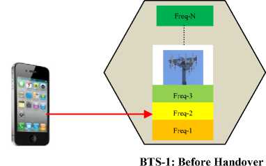
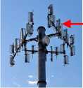
The aim here is to shift from a fading or severely interfered with frequency into a less fading or less interference frequency. As shown in Fig. 2, before handover, the UE was utilizing Freq-3, but after handover, the UE is now employing Freq-N.
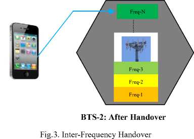
When a call changes from one frequency to another disparate frequency, this handover becomes inter-frequency handover (IEFH) as shown in Fig. 3. This figure shows that in BTS-1 before handover, the UE was assigned Freq-2, but after being handed-over to BTS-2, the UE is now allocated Freq-N. An example of this handover is that from one cell to another cell within the same cluster or different cluster. The goal of this handover is to ensure continuity of an ongoing call as the user crosses the cell boundary.
In system-based handover (SBH), the parameter is the characteristic of the cellular network. Here, the call is transferred between cells using different cellular networks, in which case it becomes an inter-system handover (IESH). An example of this is a handover from GSM to 3G UMTS. The aim is to provide call connectivity in areas where the other cellular network is either missing completely or the signal levels are poor. When a handover occurs between similar cellular networks, then it becomes an intra-system handover (IRSH). An example of this is a handover between two GSM networks.
-
V. Discussion
The first cadre of handover in the developed handover nomenclature is that based on frequency (FBH). In this handovers, the parameter of interest is the frequency of transmission. It is possible for the call to be transferred from one frequency to another within the same cell (intra-frequency handover-IRFH) as shown in Fig. 2.
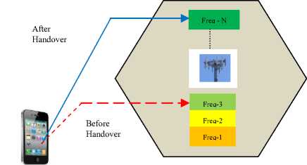
Fig.2. Intra-Frequency Handover
Handover based on access technology (ATBH) utilize media access technique as a criterion for the classification process. These media access technologies can be TDMA, FDMA, CDMA, or WCDMA. As such, a call transfer from a TDMA network to a WCDMA network is a vertical handover (VTH) while a call transfer from FDMA network to another FDMA network is a horizontal handover (HZH).
Call behavior based handover (CBBH) employ
UE-BTS connection as basis for classification. If the UE’s connection to the older BTS is broken before a connection to the new BTS can be established, then the handover is hard handover (HH) as shown in Fig. 4.
Old connection (Broken)
BTS-1

New
Connection
BTS-2
Fig.4. Hard Handover
Hard handovers utilize the network bandwidth efficiently since only one channel is utilized at any given time. In addition, the UE’s hardware does not need the capability of receiving two or more channels simultaneously; hence can be simpler and less costly. However, if the connection to the older BTS is maintained as the new connection is established to the new BTS, then it is a soft or softer handover as depicted in Fig. 5.
BTS-1
Old connection (Maintained)
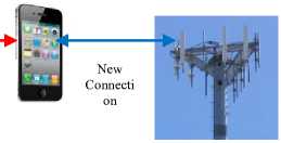
BTS-2
Fig.5. Soft Handover
Since the connection to the source BTS is terminated only when a dependable connection to the destination BTS has been setup, soft handovers have less chances of call terminations during handover.
In addition, this handover maintains concurrent channels in various base transceiver stations, hence the ongoing call can only be cut short if the entire set of channels fades or is interfered with simultaneously. Since fading and interference among cells are not correlated, there is no possibility of all channels experiencing fading and interference at the same time. This boosts the reliability of calls during handover.
During soft handovers, either the best of all received signals is utilized for data exchange or all the signals are pooled to generate a clearer replica of the signal. Softer handovers result when such combining is carried out both in the downlink or uplink. Multi-ways handovers (MWH) result when a soft handoff employs connections to more than two Base transceiver stations as illustrated in Fig. 6. Handovers based on the number of simultaneous BTS-UE communication (NSBBH) can either be hard handover (HH) where the UE communicates with only one BTS at a time, or soft handover (SH) where each UE keeps an active set for adding Base transceiver stations whose RSS are greater than a give cut-off, or removing them when the RSS falls below another cut-off.

Old connection (Maintained)
BTS-1
BTS-2
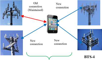
BTS-4
New connection
New connection
New connection
BTS-3
Fig.6. Softer Handover
It can also be softer handover (STH) if all the different BTS signals are combined using a RAKE receiver to yield a stronger signal. In STH, the UE communicates with different sectors (a group of cells on the same cell site) within the same cell site. In addition, it is feasible to use velocity as a classification parameter (VBH) especially in overlay/underlay architectures. In these networks, the micro-cells are designed for slow moving UEs while the macro-cells are for fast moving UEs. Here, when the UE is in the microcell and its velocity becomes too high, the call is handed over to the macro-cell, in which case it becomes a micro-macro handover (MIMAH). It is also possible for the UE moving very fast in the macro-cell to slow down to low velocities, in which case the call is handed over to a microcell (MAMIH).
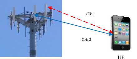
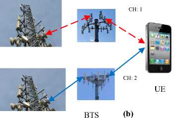
The handovers based on the BTS (BTBH) can either be intra-BTS handovers (IRBTH) where a call is transferred between the BTS frequencies or time-slots, or inter-BTS handover (IEBTH) where a call is shifted between cells controlled by different base transceiver stations as shown in Fig. 7.
BTS (a)
CH: 1---- Channel 1
CH: 2---- Channel 2
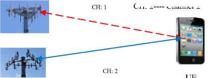
BTS (b)
Fig.7. (a) Intra-BTS Handover (b) Inter-BTS Handover
In Fig. 7(a), the UE’s frequency or time-slot is changed (broken line indicates that this channel is no longer usable, continuous line indicates the current active channel), but the UE is attached to the same BTS before and after handover (IRBTH). On the other hand, in Fig. 7 (b), the UE’s call is transferred between two base transceiver stations (IEBTH).
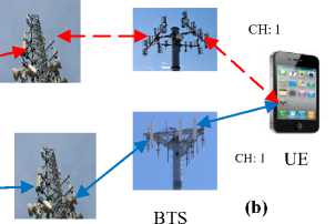
When a BSC is employed as a parameter, then the resulting handover can be intra-BSC handover (IRBSH) where a call is handed over between two base transceiver stations controlled by the same BSC, or inter-BSC handover (IEBSH), in which case the handover happens between cells under the management of disparate BSC as show in Fig. 8.
handovers depicted in Figure 2 to Figure 8 are internal handovers while the handover in Figure 9 is an external handover.
CH: 1
CH: 1
UE
(a)
BS
CH: 1--- Channel 1
CH 2:--- Channel 2
BTS
CH: 1
UE
CH: 2
BSC
(a)
BTS


BS
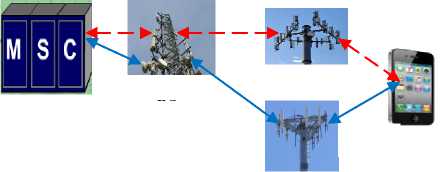
Fig.9. (a) Intra-MSC Handover (b) Inter-MSC Handover
CH: 1--- Channel 1
CH: 2--- Channel 2
BSC
Fig.8. (a) Intra-BSC Handover (b) Inter-BSC Handover
In Fig. 8(a), the UE’s call is transferred between two base transceiver stations under the control one BSC (IRBSH) while in Fig. 8 (b), the UE’s call is transferred between two base transceiver stations under the control of two base station controllers (IEBSH). It is also possible for the calls to be transferred between cells under the control of one MSC, which becomes an intra-MSC handover (IRMSH), or between cells belonging to dissimilar MSC, the inter-MSC handover (IEMSH) as depicted in Fig. 9.
In Fig. 9 (a), the source BTS and the target BTS are all under the control of one MSC (IRMSH), while in Fig. 9 (b), the source and the destination BTS fall under the control of disparate MSCs (IEMSH). When an MSC is not involved in the handover process, the resulting handover is internal handover (INTH). On the other hand, when an MSC takes part in the handover process, the handover becomes external handover (EXTH). As such, the
Handovers based on protocols can either be network controlled handovers (NCH), mobile assisted handovers (MAH) or mobile controlled handovers (MCH). In NCH, the cellular network’s handover decision is based upon its own measurement of the UE’s received signal strength at a number of BTS. Consequently, the MSC has all the information regarding the reported received signal strength for all the UE’s under its control. In MAH, the UE makes the network evaluations, passes the results to the MSC which then executes the handover decision. As such, the handover process is distributed among the UEs and the MSC. This handover is ideal in micro-cellular networks where the frequency of handovers is high. For the case of MCH, the UE measures the RSS and SIR from its surrounding Base transceiver stations and handover occurs when the RSS from the current BTS is lower than that from its neighbors by a given cut-off value. This protocol gives the UE complete control over the handover process.
In the case of mobile IP version 6 based handovers, three variants of handovers exist normally mobile IP version 6 handover (MIP6H), hierarchical mobile IP version 6 handover (HMIP6H) and Intra-Domain Mobility Management Protocol handover (IDMPH). In MIP6H, mobile IPv6 is employed as a protocol for the management of mobility in 4G networks. During handover, the unbroken communication between the UE and its correspondent is maintained by establishing a design that attaches the UE’s home address and its care-of address. In this case, the home address serves to connote its home network (HN) while the care-of address (COA) is created whenever the UE shifts from its home network to new network, during which its home network becomes invalid. The establishment of this COA is based upon router advertisement of the new network. In this setup, the UE detect inbound packets to the UE using HN while the current location of the UE is determined from the COA. At the onset of the handover process, the UE discovers the candidate handover subnet from the router advertisement received from the visited access router.
For the case of HMIP6H, local handovers are handled locally devoid of informing the home agent. To deal with global handovers, the internet in this region is partitioned into areas for local area mobility. These areas are then attached to the rest of the network using a new node, the mobility anchor point (MAP). In this arrangement, the MAP manages a number of access routers. Here, each UE has two COAs, one acting as a regional COA (RCOA) while the other as a local COA (LCOA). The UE communicates with its correspondents nodes through RCOA, hence when the UE shifts into a new domain, it has to first get this address from the MAP advertisement information. Afterwards, the UE notifies its home agent and its correspondents about its regional position. In this case, the MAP captures packets destined to the UE’s RCOA and transmits them to the UE’s LCOA.
In case of IDMPH, the UE has two COAs, LCOA and Global care-of address (GCOA). While the former identifies the UE’s current subnet, the latter identifies the UE’s domain position. It implements some modifications on the mobile IP by introducing a two-level infrastructure with mobility agent (MA) giving the UE some domain-wide steady access point. IDMPH achieves fast handover, which serves to eliminate delays in updates between the network domains. This is accomplished by predicting the incoming handover in the connection between the network and the UE using triggers from either the UE or BTS. Thereafter, the mobility agent multicasts all inbound data packets to the whole set of adjacent subnet agents (SAs).
In domain based handovers (DBH), intra-domain handovers (IRDH) involve transferring calls between networks that belong to the same realm while inter-domain handovers (IEDH) transfer calls between networks that belong to disparate realms. In handovers based on GSM generations (GGBH), first generation handovers (FSH) basically employ mobile controlled handovers where the UE’s are totally in control of the handover process. In second generation handover (SGH), mobile assisted handover is utilized where the handover decision is decentralized such that the UE takes network measurements and the MSC carries out the handover decisions.
For the case of 2.5GH, is a GPRS handover in which three states (idle, standby and ready) are utilized to handle the handover process. In idle mode, the UE is not connected to GPRS while in standby mode the UE is bond to GPRS and carries out cell selection locally. Any data, signaling or page responses make the UE to shift to ready mode.
The 2.75GH is an enhanced data rates for GSM evolution (EDGE) handover where the UE is charged with handover responsibilities while in TGH, a Universal Mobile Telecommunications Network (UMTS) soft handover is carried out by having the UE establish communications with its source as well as neighboring cells. In 3.5 GH, High Speed Packet Access (HSDPA) soft handover is implemented while in 3.9GH, long term evolution handover occurs in which the mobile users’ connection to the source BTS is terminated before a new connection can be established to the next BTS.
Under 4GH, an LTE-Advanced handover occurs in which the connection to the source BTS is terminated before a new connection can be established to the target BTS. On the other hand, CABH has two variants namely centralized handover (CH) and distributed handover (DH). In the former handover, the network is fully in charge of the handover process, while in the latter, the UE is absolutely and autonomously responsible for the call transfers from one cell to another.
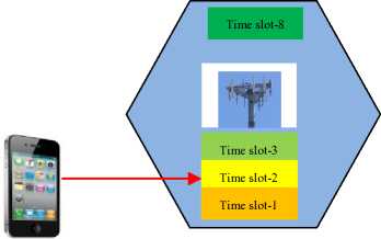
It is also probable to classify handovers based on time-slots, to yield intra-time slot handover (IRSTH) and inter--time slot handover (IETH) as shown in Fig. 10 and Fig. 11 respectively.
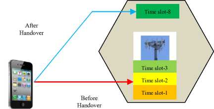
Fig.10. Intra-Time slot Handover
Before Handover
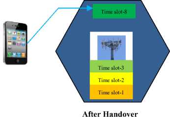
Fig.11. Inter-Time slot Handover
As shown in Fig. 10, the UE is allocated time-slot 2 before handover and slot-8 after handover. Therefore, in IRSTH, the UE remains in the same BTS but is allocated a different time slot for signal communication. In a GSM cellular network, the total available time slots is eight and each UE with the BTS’s control is allocated one of these time slots for signal transmission and reception. Instead of remaining idle for the next six time slots, the UE uses these time slots to scan for the signal beacons from adjacent cells and passes information about the quality of these beacons to the network. For the case of IETH, a call is transferred to a different cell and assigned a disparate time slot for signal transmission and reception.
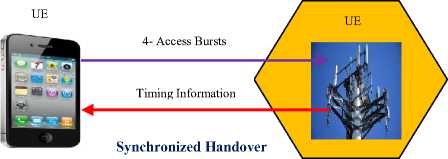
Fig. 11 shows that before handover, the UE was allocated time slot-2 but after handover, the UE is now allocated time slot-8 (IETH). Handovers hinged on synchronization (SYBH) can be synchronized handovers (SYH), synchronized source and target BTS with time offset (SYTH) or non- synchronized handovers (NSYH). In SYH, the network provides the UE with all the facts needed for the handover process. Thereafter, the UE transmits four access burst on this new cell so as to fine-tune the timing information.
For the case of SYTH, the network informs the UE of any time offset between the source and the destination BTS, after which the UE carry out the modification to align itself with the target BTS timings. NSYH takes place when the UE sends sixty four access bursts on the target cell so as to establish the BTS’ correct timing and subsequently, the UE can now access and re-establish connections with the new BTS.
LOSH exist in two forms, line of sight handover (LOSH) and non-line of sight handover (NLOSH). LOSH happens when calls are transferred between two or more BTS where the signals travel in straight lines among the base transceiver stations. This handover is ideal in environments with no obstacles among the communicating entities. On the other hand, NLOSH takes place calls are transferred between a BTS that communicates through line of sight and another BTS that does not utilize line of sight communications. This handover is suitable in situations where many obstacles exist among the communicating parties. Consequently, NLOSH can be helpful when the UE travels in a straight line street and then turns round a corner. During the movements along the straight line street, LOS BTS is utilized but when the UE turns around a corner, an NLOSH BTS is employed.
Handover based on under-lays and overlays (OUBH) can be broken down into MIMIH, MIMAH, MAMIH and MAMAH. The first handover occurs between micro-cells, where UE’s movements are at very low velocity, hence suitable for pedestrians. The second handover happens when a call is shifted from micro-cells to macro-cells, hence ideal for situations in which the UE suddenly increases its velocity up to between 350km/h and 500km/h. These handovers are depicted in Fig. 12.
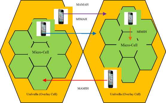
Fig.12. Overlay/Underlay Cells
The bigger hexagons represent macro-cells (overlays) while the smaller hexagons represent micro-cells (under-lays). The third handover takes place when a call is transferred from macro-cells to micro-cells, thus suitable when a high velocity UE suddenly slows down. The fourth handover arise when a call is conveyed between macro-cells, therefore ideal when high velocity UE moves from one cell to another cell.
LIBH is of two variants, LIH and NLIH. For the first handover, the global positioning system (GPS) is needed to provide UE direction and velocity, both of which are required in the selection of the target BTS. In the latter handover, only the velocity of the UE and the BTS coverage areas are required. Handovers hinged on cell crossings (CXBH) can either be intra-cell handovers (IRCH) or inter-cell handovers (IECH). While the former handover takes place within a single cell, the latter involves call transfers among many cells. In IRCH, a single BTS is required since the UE moves within a cell, while IECH needs more than one BTS because the UE moves among various cells.
It is important to note that both NSYH and IESH can be decomposed to yield GSM to UMTS/WCDMA handovers (GUWH) and UMTS/WCDMA to GSM handovers (UWGH). Since GSM, UMTS and WCDMA are different systems, these handovers qualify to be considered inter-system handovers (IESH). Similarly, both GUWH and UWGH are all non-synchronized handovers (NSYH). The non-synchronized handovers can further be regarded as blind handovers (BLH) or compressed mode handovers (CMH). BLH take place when the source BTS (SBTS) transfers the UE to the target BTS without setting the timing information for the new cell. The SBTS takes network measurements and selects the BTS with optimum figures of merit and passes these details to the UE.
As such, the UE has to find the broadcast channel (BCCH) of the new cell and obtain timing information. CMH takes advantage of the fact that out of the 8 time slots, the UE transmits only on one of them and receives on only one of them. Hence instead of remaining idle for the remaining 6 time slots, the UE analyzes the characteristics of the neighboring Base transceiver stations and chooses one with best RSS. Thereafter, it transfers the call without any timing information of the target cell.
-
VI. Limitations of The Current Cellular Handovers
The security aspects in handovers revolve around confidentiality, integrity and availability. Poor handover procedures lead to long delays that can cause packet losses and call drops. If the user traffic is not distributed equally among the Base transceiver stations in a cluster, some Base transceiver stations can be overloaded while others will be redundant. Overloaded Base transceiver stations can breakdown, leading to unavailability. On their part, packet losses can compromise integrity of the transmitted data since what the receiver gets is totally different from what was sent. Co-channel interference can also corrupt the transmitted data, affecting the integrity of the transmitted data.
Since handover is required to take place very fast so as to assure seamless connectivity, authentication can introduce delays due to the heavy signaling that has to be accomplished among the communicating entities. As such, handed-over calls are not authenticated at the target cell. Therefore, it is possible for the UE to request for a channel in the target cell but if the UE takes long to connect to the requested channel, an intruder can take over the requested channel [7]. This is a session hijacking and it may enable the intruder to get information from the other communicating party, hence compromising confidentiality of the communication process.
To address these challenges, delays and interference should be eliminated in the handover process. This is particularly important since the handover process, if poorly managed, can interfere with new calls initiated by the UEs [12]. This is because some systems are designed to give priority to handover calls hence new calls can be blocked. This adds to systems unavailability. As such, in this paper, the nomenclature developed is evaluated with regard to packet losses, delays and interference.
An efficient handover process ensures that the mobile users enjoy seamless connectivity as they move from one cell to another in a cellular environment. However, numerous researches in this area have revealed setbacks in the way the handover is handled. To start with, FBH change the frequency assigned to the UE when the current frequency experiences interferences or fading. This requires that some frequencies be preserved for the handed-over calls; otherwise the ongoing calls will be dropped if no frequencies are available [14].
In IRSH, a variant of SBH, handovers occur between different platforms. As such, compatibility of the systems involved in the handover process is major issue here. Handovers that involve different access technologies are cumbersome to carry out while fulfilling the various quality of service for wireless connectivity such as low latency, low packet losses and low call blocking probability [15].
Call handover hinged on call behavior such as hard handover require that different frequencies be employed in adjacent cells, which puts some strain on frequency, being a scarce resource. In addition, since it utilizes only one frequency at a time, the ongoing call experiences a break before being shifted to the target BTS, hence there is low probability of a success. An ongoing call can therefore be dropped [12] as the UE tries to re-establish connections to the target BTS. Lack of free channel or time slot in the target can also contribute to call drops.
Delay is another major issue in hard handovers, caused by the need to carry out groundwork measurements to establish BTS with the strongest signal power before the UE can execute decision [16]. In soft and softer handovers, more than one channel is utilized during the handover process. This necessitate that adjacent cells operate at the same frequency since the UE rarely have multiple transmitters and receiver for handling signals with different frequencies. This may increase co-channel interference, and is wasteful since more than one channel is required to sustain a single call [17]. As such, soft handovers are mostly applied in CDMA systems where the disparate Base transceiver stations utilize similar frequency with dissimilar code words. When different frequencies are utilized in neighboring base transceiver stations, soft handovers call for sophisticated hardware in the UE, with the ability of processing a number of channels concurrently. Each signal calls for a RAKE finger module to process it.
Handovers based on velocity require that the GPS be employed to provide velocity or algorithms based on maximum Doppler frequency to estimate the UE velocity [18]. These algorithms have high time complexity, consuming a lot of power. Since UEs operate on batteries, this may shorten battery life-time. In addition, some UEs may not be GPS enabled and for those that are GPS enabled, the received signals from GPS may be weak at times, making velocity determination difficult.
For the case of handovers involving two BTS, BSC and MSC, the setback is the complexity of the signaling involved and the resulting extra overhead which wastes cellular bandwidth [19]. In external handover, the shortcomings are that it necessitates that the UE measure the signal quality from sixteen disparate neighbors during a call, select the best seven cell identity (base station identity code - BSIC) and send this information to the network. As [12] explains, thereafter, this information is passed to the BSC and MSC to facilitate the handover decision. This is repeated at an interval of one second, hence wastes the UE’s resources such as battery power, processor time and bandwidth.
As [12] discuss, network controlled handovers are not ideal for quickly changing environment and densely populated areas due to their long delays. In mobile assisted handovers, the handover process can experience a delay of one second. This delay is too long to offset the corner effect, which is characterized by an abrupt large drop in signal strength when the UE navigates around a corner. This is occasioned by loss of the line of sight between the UE and the BTS. For mobile controlled handovers, the UE transfers calls autonomously. The setback is that the UE does not have signal quality information of other UEs. As such, it is possible for the handed-over call to cause interference to other mobile users.
MIP6H is unable to manage handover delays that result from identifying a new subnet, establishment of new COA, exchanging information between the UE and its home agent whenever the UE changes its position within the cellular network [20]. In HMIP6H, the challenges are that it requires mobility anchor point (MAP), and two care-of addresses, which increases implementation complexity. In addition, if MAP handles a large number of UEs in one domain, then its load increases. This may become a bottleneck, consequently affecting the speed of data transfers to UEs. The situation may deteriorate for all UEs within the same domain if this MAP is down or malfunctions. To address this, redundant MAPs may be used but this may bring in other challenges such as dynamic load balancing among MAPs . Unlike HMIP6H which handles both intra-domain and inter-domain handovers, IDMPH concerns itself with intra-domain location updates [21]. Another problem is that some mobility agents are likely to be busy multicasting packets when the corresponding subnet agents are in control of numerous UEs and their associated movements, while other mobility agents are redundant. Consequently, the overloaded mobility agents may lead to communication instability and hence the increase in packet loss probability during handover.
In DBH, calls may be dropped if the target domain’s subnet agent is fully occupied by its current UEs [20]. Handovers based on GSM generations (GGBH) have a number of setbacks as discussed in [2]. To start with, first generation handovers are fully managed by the network and the current connection is terminated before a new connection to the target BTS can be established; hence inherits all the shortcomings of network controlled handovers and hard handovers discussed above.
For second generation handovers, the UE takes measurements while the network carries out the handover decision, hence is affected by the shortcomings of mobile assisted handovers already discussed. The 2.5 GH is employed in GPRS and it requires numerous access points for it to be successful. On the other hand, 2.75GH is employed in EDGE and this handover can raise the probability of connection breakdown.
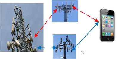
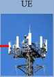
TGH is implemented in UMTS and involves establishing multiple connections to neighbouring cells during the handover process, which wastes the network bandwidth. It is also possible for the UE involved in TGH to receive signals from two sectors that are under the control of the same cell site as shown in Fig.13.
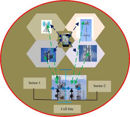
Fig.13. UMTS TGH
This may be as a result of multipath propagation occasioned by reflections from obstacles such as buildings. However, to process these signals, a RAKE receiver is required at the UE. Moreover, as Fig. 13 shows, the UE is using four channels to serve only one call. Since it requires that adjacent cells use similar frequencies, this is only possible for time division multiple access (TDMA) or code division multiple access (CDMA) networks but not applicable in frequency division multiple access (FDMA). The 3.5GH is applied in high speed data packet access (HSDPA), where handover decisions are founded on channel quality information given by the UE, its category and the type of service. Its drawbacks are that it requires configuration of the channel coding pace, link adaptation and modulation technique [2].
In long term evolution (LTE) networks, 3.9 GH is employed, but is only ideal for high velocity UEs for between 350Km/h and 500Km/h as noted in [22]. In 4GH, the UE utilizes one channel at a time and this channel is released before a new channel in the target BTS can become usable. As such, [23] explain that this handover can be disruptive for ongoing calls or data transmissions.
Handovers based on time slots can only be successful if the target cell contains some free slots to allocate the handed-over calls, otherwise the call will be dropped. Channel reservation can help alleviate call dropping, but can lead to bandwidth wastage is it cannot adjust to the network conditions [24]. On its part, synchronized handover necessitates that the UE send out four access bursts to obtain the target BTS timing information, which adds to the signaling overhead.
For synchronized source and destination Base transceiver stations with time offset, the network must provide the UE with this time offset, otherwise the UE will be unable to perform some timing adjustments. Non-synchronized handovers prompt the UE to transmit sixty four access bursts on the target BTS so as to establish and fine-tune the timing information [19]. This leads to bandwidth wastage that could have been utilized for user payload transmissions. Fig. 14 gives a summary of these synchronization-based handovers.
In CABH, handovers can be centralized or decentralized. The shortcomings of the former is that the handover takes long due to the heavy signaling involved, which may lead to call drops. In the latter handover, the handover decisions lie with the UE [12]. Here, the UE does not have information regarding the signal quality of other adjacent UEs. Consequently, the UE might execute a handover that causes interference to its neighbors. In addition, the UE spends huge amounts of power measuring signal strengths from adjacent base transceiver stations and interference levels on all links [2]. LOSH require that signals travel in straight line among communicating parties during handover. As such, obstacles can severely interfere with the handover process and may lead to ping-pong effect.
In OUBH, the UEs must be capable of moving with different velocities within the coverage area [25]. For instance, macro-to-micro-cell handover is only possible when the UE slows down its velocity while micro-to-macro-cell handover can only take place if the UE accelerates to higher velocities [23]. Constant low velocities will result into MIMIH while constant high velocities will lead to MAMAH.
employed in cellular networks. In particular, delay in handover procedures is a major challenge, especially for delay sensitive applications such as mobile banking applications. Using one or few parameters in the handover decision can lead to inaccurate or delayed handover [26]. As such, a novel handover is required that employs many parameters in the handover process such that at given instance, a sound and fast handover is executed as discussed in the sub-section that follows.
UE
Time Offset

Synchronized Handover with Time-Offset

VII. Proposed Authenticated Multi-Factor Handover
In GSM cellular networks, handovers are very significant in ensuring seamless connectivity as mobile users move from one cell to another. In addition, efficient handovers are required in order to guarantee load balancing among the GSM BTS, BSC and MSC so as to prevent overloading others and the subsequent breakdown. When users change their bahaviour, for instance by decelerating suddenly, handover must take place from a macro-cell to a micro-cell. An efficient handover should attempt to avoid fading or severely interfered channels by transferring calls to better channels.
Poorly designed handovers lead to delays between handover request and handover execution. It is also possible for the handed-over call to be dropped if there is inadequate load balancing such that some Base transceiver stations lack free channels while other Base transceiver stations are idle. To guarantee quality of service during the handover process, this paper proposes an authenticated multi-factor neuro-fuzzy handover.
UE

64- Access Bursts
Timing Information
Non-Synchronized Handover
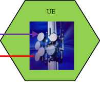
Fig.14. Synchronization-Based Handovers
Handover based on location information suffer from a number of setbacks. To start with, the network has to set some supplementary data bearer for each mobile relays. Secondly, these relays must convey GPS information in their measurement report [18]. In addition, these handovers may not be strong in areas where GPS signal reception is poor or sporadic, such as in lengthy tunnels or mountainous regions.
In this section, the developed handover nomenclature has been used to provide a classification that has helped review the shortcomings of the various handovers
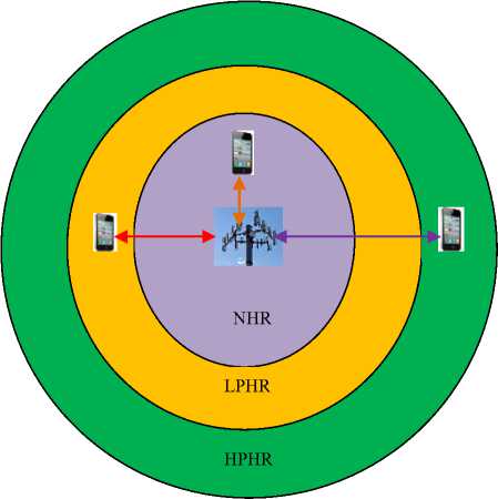
Fig.15. BTS Coverage Area Partitioning
The first premise of the proposed handover is that the handed-over calls must be authenticated before they can start using the allocated channel. This can help mitigate GSM session hijacking attacks when calls are not authenticated at the new BTS. The idea will be to partition the BTS coverage area into three regions: no handover
regions (NHR), low probability handover regions (LPHR) and high probability handover regions (HPHR) as shown in Fig. 15.
As this figure illustrates, the bigger concentric area represents the high probability handover region, adjacent to it is the low probability handover region while at the innermost part is the no handover region. At the center of all these regions is the serving BTS and the UE is free to move to any of these regions at any particular time.
At NHR, the signal strength from the source BTS is very strong, and so the UE should not scan the neighboring cells. When at LPHR, the signal strength from source BTS is relatively strong, and at this point, the UE may start analyzing beacons from the surrounding cells and send this information to the BSC.
At the HPHR, the source BTS signal strength is very weak and the UE should be handed-over to a cell with better figures of merit. This is the region where more than one BTS coverage areas overlap as demonstrated in Fig. 16.
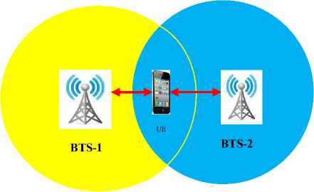
Fig.16. BTS Overlapping Regions
The region occupied by the UE is an overlapping region between BTS-1 and BTS-2. As shown in the figure, the UE receives signals from both BTS-1 and BTS-2. The handover optimization process then entails making a faster decision on which BTS should take charge of the UE’s communication. In this region, a handover based on distance from the BTS will fail since the UE is now at equidistance from both BTS-1 and BTS-2. In addition, assuming that both BTS emit the same amount of power, then even a handover based on signal strength will not materialize since the signal strength at this region will be equal. As such, additional parameters must be included in the handover decision process.
This paper therefore proposes additional figures of merit such as co-channel interference, power density, received carrier power, BTS traffic density, call blocking probability, cell spectral efficiency, effective isotropically radiated power and path loss to be utilized in conjunction with distance between the BTS and the UE. This will ensure that before a handover is executed, the target cell is thoroughly evaluated using all these parameters and hence the call is likely to be continued under better quality of service.
Co-channel interference parameter will ensure that the target BTS experiences less interference compared with the current BTS. Power density and received carrier power will guarantee that the signal levels in the new BTS are strong enough to sustain an ongoing call. The BTS traffic density will help ensure load balancing such that system overloading is mitigated. Call blocking will guarantee that the handover process does not interfere with new calls being initiated by the UEs. For the case of cell spectral efficiency, it will ensure that the handover process leads to overall improved utilization of the network bandwidth while effective isotropically radiated power will guarantee that the UEs can receive the BTS signals uniformly in all directions at various distances from the BTS. On its part, path loss is instrumental in guaranteeing that the new cell does not expose the handed-over calls to major path losses that may lead to packet losses or delays.
Since the UE had already scanned the neighbouring cells at the LPHR and passed the information to the network, the BSC already has information about the state of beacons from the UE’s adjacent cells. Therefore, the BSC can select the best of them all and handover the call without any delay.
It has been noted that handover delays are the main reasons for the exclusion of authentication in the conventional cellular network handovers. Since these delays have now been reduced by the timing advance at the LPHR, the recovered duration can be utilized for authenticating the UE and the BTS. Taking authentication credentials (AC), validation results (VR), acknowledgement (ACK), new channel (NC), BTS timing information(BTI), handover (HO) and packet transmission (PTR) as constituents of the authentication process, a three-way authentication will be carried out as depicted in Fig. 17.
UE
Send AC
Reply with VR
ACK for receipt of VR
BSC
Fig.17. GSM Handover Authentication
As shown here, the UE will first send the AC to the BSC, which will validate these credentials against values in its database. The BSC will thereafter send the VR to the UE. Upon receipt of the VR response from the BSC, the UE will complete the authentication process by acknowledging the receipt of the VR. Provided that the VR were correct, the BSC will inform the target BTS under its control to allocate a new channel for the UE and send this new channel and its timing information to the UE. Upon receipt of NC and BTI, the UE shifts to the new BTS and begins packet transmissions in this new BTS.
The second working principle of the proposed handover is that it should encompass a number of criteria for the handover process. The current handover procedures have been observed to be majorly based on RSSI, UE velocity and distance between the BTS and the UE. These parameters are insufficient as they do not apply to all users in all situations. For instance, handovers based on RSSI can lead to ping-pong effects when the UE moves through an obstacle that may block signals from the source BTS. Here, the RSSI from the neighbor BTS may momentarily be stronger than that from the source BTS due to obstacle signal blockage. As such, when the user moves past the obstacle, the UE may be handed back to the previous BTS. Since handovers are expensive in terms of the signaling traffic involved, the ping-pong effect lead to low spectral efficiency and new calls may be blocked. On the other hand, velocity based handovers are ideal for users in motion, but not for stationary UE such those in offices. When the distance between the BTS and UE is employed as handover criteria, delays may crop in when the user is in equi-distance from two or more base transceiver stations.
The neuro-fuzzy algorithm architecture illustrated in Fig. 18 will be significant during the handover decision making phase and constitute the third requisite for the proposed handover. As the figure demonstrates, the main components of the neuro-fuzzy architecture are the knowledge base, database, inference engine, explanation facility and the UE. The knowledge base consists of handover conditions expressed in modus ponens statements that will evaluate to true or false. The database on its part is a repository of all handover figures of merit identified such as co-channel interference, power density, received carrier power, BTS traffic density, call blocking probability, cell spectral efficiency, effective isotropically radiated power and path loss.
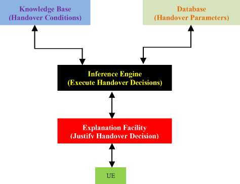
Fig.18. Neuro-Fuzzy Algorithm Architecture
The inference engine is instrumental in linking the rules in the knowledge base and facts in the database, and hence facilitates the execution of the handover decisions. The explanation facility is vital in justifying the choice of the target BTS. The neuro-fuzzy rules combines the various criteria using AND or OR logic connectors to arrive at an appropriate conclusions, which can be to deny or grant the handover to the mobile user.
At any given moment during the time when the UE is in the cell overlapping region, the BSC utilizes this proposed handover to reduce the handover latency and the attacks mentioned in the sub-sections above. Fig. 19 summarizes the proposed handover process.
As this figure shows, both BTS-1 and BTS-2 are within BSC control (BTS-1 and BTS-2 are all within the bigger circle) and the UE is moving from BTS-1 towards BTS-2. At its current position, the UE is in a region where BTS-1 and BTS-2 are overlapping. At this point, the BSC is in charge of the handover process but before UE can be shifted to BTS-2, it has to send its authentication credentials to the BSC for validation. This constitutes the authentication phase (AUP). On condition that the authentication credentials are correct, the BSC uses its multi-factor neuro-fuzzy algorithm (MFNFA) to determine the best target BTS to handover the UE to. For simplicity, BTS-2 has been taken to be the best target BTS to offer best quality of service to the UE.

Fig.19. Operation of the Proposed Handover
-
VIII. Conclusion
This paper sought to carry out a security analysis of the current GSM handover techniques. This analysis was based on the three goals of information security consisting of confidentiality, integrity and availability. It has been observed that handover procedures, if not well designed, can lead to poor functional and information security.
Delays during handover procedures has been noted to contribute to packet losses, call drops, increased call setup time and session hijacking. Lack of proper load balancing has been established to be capable of causing system overload and breakdown.
All these can affect confidentiality, integrity and availability of the transmitted data in one way or the other. Towards the end of this paper, an authenticated multi-factor neuro-fuzzy handover has been proposed. This handover takes a number of criteria into consideration during the handover decision making phase. This ensures that the handover is actually necessary and that the target cell is capable of providing the required quality of service for the ongoing call or data transfers. Since handovers consume a considerable network bandwidth in form of the signaling among the communicating entities, unnecessary handovers need to be prevented. Ultimately, this lead to high spectral efficiency and new calls being initiated are unlikely to be blocked. These are the objectives of the proposed handover. Future work in this area involves the practical design and implementation of this handover in a GSM environment.
References Security evaluation of cellular networks handover techniques
- O. Osahenvemwen & F. Odiase, “Effective management of handover process in mobile communication network”, Journal of Advances in Technology and Engineering Studies, Vol. 2, Issue 6, pp. 176-182, (2016).
- A. Babiker, H. Ahmmed & S. Ali, “ Comparative Study 1st, 2nd, 3rd, 4th, Generations from Handoff Aspects”, International Journal of Science and Research, Vol. 5, Issue 6, pp. 934-941, (2016).
- B. Ravishankar, “Authentication and related Threats in 2G/3G/4G Networks”, Department of computer science, Oxford University, pp.1-64, (2016).
- P. Copet, G. Marchetto, R. Sisto & L. Costa, “Formal Verification of LTE-UMTS Handover Procedures”, IEEE, pp.1-8, (2015).
- Y. Lai, P. Cheng, C. Lee, & C. Ku, “A New Ticket-Based Authentication Mechanism for Fast Handover in Mesh Network”, Department of Photonics and Communication Engineering, Asia University, Taichung, Taiwan, pp. 1-18, (2016).
- Y. Lin, W. Longjhuang & C. Chen Yang, “Enhanced 4G LTE Authentication and Handover Mechanism”, International Journal of Electrical, Electronics and Data Communication, Vol. 3, Issue 9, pp. 45-47, (2015).
- K. Kastell, U. Meyer & R. Jakoby, “ Secure Handover Procedures”, Department of Computer Science, Darmstadt University of Technology, pp. 1-5, (2013).
- E. Donald & F. Nosa, “Analysing GSM Insecurity”, International Journal of Research and Scientific Innovation, Volume 3, Issue 10, pp. 10-18, (2016).
- L. Jagadesh, I. Kullayamma & V. Naresh, “Handover Analysis”, International Journal of Engineering Research and Applications, Vol. 1, Issue 2, pp.287-291, (2015).
- D. Girhepunje & A. Bhute, “A Survey: Handover scheme of High-Speed Train Environment”, International Research Journal of Engineering and Technology, Vol. 03 Issue 3, pp. 998-1002, (2016).
- D. Agrawal, & M. Mankar, “Mobility Management Vertical And Horizontal Handover Decisions In Heterogeneous Wireless Networks Using OMNET”, Vol. 7, Issue 2, pp. 557-562, (2016).
- A. Galadima, “Analysis And Optimization Of Inter Cell Handover Dynamics In A GSM Network”, Masters Thesis, Faculty Of Engineering, Ahmadu Bello University, Zaria, Nigeria, (2014).
- H. Kaur & A. Kaur, “Various Handover Management Techniques In GSM Cellular System”, International Journal of Advanced Engineering Research and Science, Vol. 1, Issue-2, pp.28-33, (2014).
- S. Acharya & T. Gaba, “A Review: Handover in 3G/UMTS Network”, International journal of Emerging Trends in Science and Technology, Vol. 1, Issue 3, pp. 332-339 (2014).
- J. Karishan “Study and Analysis of Call dropping and Handover Problem in cellular system”, International Journal of Advanced Research in Computer Engineering & Technology , Vol. 5, Issue 6, pp. 1776 -, 1777 (2016).
- R. Hasdah & A. Kumar, “Study Of Soft Handover In Third Generation Cellular Network”, International Journal of Innovative Research in Technology & Science, pp. 1-8, (2015).
- C. Sayankar & N. Mane, “Handover Scheme for Mobile Relays in LTE-A High Speed Rail Network: A review”, International Journal of Innovative Research in Computer and Communication Engineering, Vol. 4, Issue 4, pp. 6933- 6936, (2016).
- T. Juang, H. Lin & D. Lin, “An Improved Location-Based Handover Algorithm for GSM Systems”, Institute of Computer and Communication, National Taipei University of Technology, Taipei, Taiwan, pp. 1-13, (2014).
- D. Sharma & K.Singh, “Analysis of Handover Initiation using Path Loss to Sustain QoS”, International Journal of Scientific & Engineering Research Volume 3, Issue 5, pp.1-6, (2012).
- N. Haider, “A Handover Technique For Inter- And Intra- Domain Proxy Mobile IPv6 In Vehicular Network Environment”, Doctor of Philosophy Thesis, Faculty of Computing Universiti Teknologi, Malaysia, (2013).
- L. Chunming & C. Zhou, “Challenges and Solutions for Handoff Issues in 4G Wireless Systems An Overview”, International Latin American and Caribbean Conference for Engineering and Technology, pp.1-6, (2004).
- S. Katiyar & K. Agrawal, “Hierarchical Cellular Structures in High-Capacity Cellular Communication Systems”, International Journal of Advanced Computer Science and Applications, Vol. 2, Issue 9, pp. 51-57, (2011).
- M. Shiuan P. Lin, & W. Chen, “An Enhanced handover scheme for mobile relays in LTE-A high speed rail network,” IEEE Transaction on vehicular technology, Vol. 64, Issue 2, pp 743-755, (2015).
- G. Abednego, D. Danjuma & G. Buba, “The Analysis Of Inter Cell Handover Dynamics in A GSM Network”, International Journal of Innovative Research in Science, Engineering and Technology, Vol. 3, Issue 6, pp. 13444- 13451, (2014).
- S. Banerjee, M. Hempel & H. Sharif, “A Survey of Wireless Communication Technologies & Their Performance for High Speed Railways”, Journal of Transportation Technologies, Vol. 6, pp. 15-29, (2016).
- U. Kumaran & K.Jeyakumar, “Multi-Criteria Based Network Selection Strategy in Multi-Radio Access Network for Vehicular Communications” International Journal of Applied Engineering Research (IJAER) Vol. 10, Issue 16, pp. 37003 –37008, (2015).
