Semi-Distributed Coordinative Switch Beamforming with Power Scheduling

Author: Ying Liu, Fangjiong Chen, Fei Ji, Xiaodong Chen, Shangkun Xiong
Journal: International Journal of Computer Network and Information Security(IJCNIS) @ijcnis
Article in issue: 2 vol.3, 2011.
Free access
Beam cooperative scheduling of a downlink transmission is an important technique to improve the spectrum efficiency in next generation mobile networks. This paper focuses on switched beams (the emission angles of the beams are fixed) and proposes a joint beam-power coordinative scheduling algorithm among neighbor sectors in the downlink of mobile systems. Each sector coordinates the applied order and transmitted power of the beams with adjacent interfering sector, so as to reduce inter-sector interference and maximize throughputs. The scheduling problem is modeled as a constrained optimization problem and solved by our proposed iterative approach. Computer simulation shows that the proposed approach significantly outperform the existing round robin beam servicing approach and the approach that applies only beam cooperative scheduling.
Cellular System, Cooperative Beam Scheduling, Constrained Optimization
Short address: https://sciup.org/15011008
IDR: 15011008
Text of the scientific article Semi-Distributed Coordinative Switch Beamforming with Power Scheduling
Published Online March 2011 in MECS
The next generation of wireless networks will be based on the OFDMA (Orthogonal Frequency Division Multiple Access) radio transmission technology and will use antenna arrays based MIMO (Multi-Input Multioutput) technology to achieve high spectral efficiency [1]. The system will also adopt full frequency reuse among the cells to realize high transmission speed. However, full frequency reuse introduces significant interference among adjacent sectors [2]. How to reduce inter-sector interference becomes an important problem.
As a low complexity interference suppression technology, beamforming in the downlink transmission has two patterns to increase cell coverage as well as improve cell edge spectral efficiency. In the pattern of adaptive beamforming, antenna array’s weights change according to user’s direction-of-arrival. This pattern works well but requires complex signal-processing and additional radio frequency (RF) chain to track signals. In the pattern of switch beamforming, the emission angle of
This work is supported by the Fundamental Research Funds for the Central Universities (No. 2009ZM0005) and the Natural Science Foundation of Guangdong Province, China (No. 9351064101000003).
each beam is fixed and multiple narrow beams together cover a sector-wide area. It is not a theoretically optimum way of using multiple antenna elements, but it presents an excellent tradeoff between performance and complexity. It requires only a single dynamic switch to control antenna handoff [3]. We focus on the switch beamforming in this paper.
The WIMAX system applies switch beamforming in the downlink transmission, where the downlink subframe is partitioned into several time slots [4]. Each sector in a slot chooses one from a predetermined set of beams to serving users that lie within that beam. A simple round robin or random beam serving approach was applied. This beam switching scheme is distributed since it does not need to exchange information between sectors. Hence it is computationally efficient. However, Beams overlap in a slot is possible to occur, which causes significant intersector interference and lead to poor spectral efficiency. Hence, this approach may not always be desirable.
Coordinative beam switching schemes have been proposed. Most existing beam coordinative scheduling algorithms require a cluster center to perform beam scheduling for all sector in this cluster. Such cluster usually includes a large number of sectors. The centralized algorithm is both computationally expensive and also requires significant backhaul resource for exchanging information [5-6].
As a tradeoff between distributed and centralized schemes, semi-distributed beams switching schemes, which Coordinative beams between adjacent sectors, becomes an interesting topic. Ref.[1] proposed a semidistributed algorithm, in which each sector can get the optimal beam applied order independently by coordinate transmissions between sectors. In [1] the transmitted powers of all beams are identical. Such power scheduling scheme is optimal when users are uniformly distributed in the coverage area. Since in practice uniform distribution of users is not common, identical power allocation for all beams may not be desirable. In this paper we propose a semi-distributed joint beam-power coordinative scheduling algorithm among neighbor sectors in the downlink of mobile systems. The transmitted power of each beam is based on the current user distribution to improve power efficiency and maximize system throughput.
-
II. B EAM C OOPERATION S CHEDULING
The semi-distributed algorithm proposed in [1] only considers two facing sectors. The scheduling beams in the coordination area are illustrated in Fig.1.
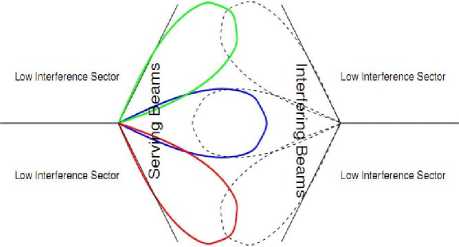
Figure1. Two facing sectors in the coordination area
Consider any sector (called sector A ) and assume that it can use one of M beams while the sector facing it (called sector B ) can use one of N beams. We assume that a scheduling period (a subframe) is partitioned into several time slots and in each slot a single beam is used in each sector. In other words, one beam pair in the coordination area is chosen from the possible M * N beam combinations in a slot. In order to keep the fairness of beams, the scheduling period should have T = min( M,N) slots at least and each beam could be chosen only once in each period.
The outline of this semi-distributed algorithm is as follow. At the beginning of a scheduling period, each sector in the coordination area calculates the achievable utility of itself for each beam pair independently. Then adjacent sectors exchange the utility information through the direct X2 interface. Finally sectors can determine the beam applied order to achieve the goal of maximizing the sum utility over all sectors in the coordination area.
For a given beam pair, the achievable utility of each sector in a slot can be calculated explicitly and easily. In order to determine the utility gain for each beam pair we must first determine the achievable SINR with the corresponding pairs. Assume there are S users that lie within the coverage of beam m of sector A and users can work only when sector A use beam m . For example, if sector A use beam m and sector B use beam n , user i that lie within the coverage of beam m can measure and report the SINR , denoted as γm,n(i) , of this beam pair to the serving base station.
Let r ˆm,n( i ) denotes the corresponding average rate of user i at the former scheduling period and r m,n ( i ) represents the average rate at the current scheduling period. r m,n ( i ) is updated based on x * m , n ( i ) , the number of resources allocated to user i .
r m , n ( i ) = ar m , n ( i ) + (1 - a ) x m , n ( i ) M1 + Y m , n ( i )) ( 1) Where a is the filter coefficient that is chosen based on the desired time frame over which the utility requirement is averaged [7].
This approach uses a throughput dependent utility function which represents the benefit of the connection provided to the user. The utility of user i is given by u„n (i) = ln(rm,n (i)) (2)
where rm, n(i) represents the present filtered throughput of the user i .The decision variable to determine the achievable utility is the number of resources allocated to user i .
. The proportionally fair allocation algorithm for user fairness is applied in this algorithm. A utility function must be a concave and non-decreasing function of the throughput. The throughput is a linear function of the number of resources allocated to user. Hence the utility as a function of the number of resources allocated to user is also concave and non-decreasing. The optimal number of resource allocated to user can be obtained by iteratively allocation [7].
Assume there are Q resources in each sector. Let x*m,n (i) denote the optimal number of resource allocated to user i and sm,n (i) denote the resource allocation coefficient of user i . x*m,n (i) is given by S x ^^i) = -1 (Q +^ sm,(i)) — sm,(i) (3) d i=1
s m , n ( i ) =
ar ˆ m , n ( i )
(1 - a )ln(1 + Y m , n ( i ))
Similarly calculate the utility of rest users in beam m sector A . Finally we can determine the sum utility of sector A in a slot when using beam pair ( m , n ) as
F m , n ( A ) = lL U mn ( i ) (5)
i = 1
Using the previous algorithm sector B can also calculate the achievable sum utility for each beam pair in a slot and define Fm , n ( B ) as the utility of sector B .
However this information is insufficient for each sector to determine the optimal pair independently. The sector also needs the utility information of facing sectors in the coordination area. Hence adjacent sectors need to exchange the utility information through the X2 interface
Consider sector A can use one of M beams while sector B can use one of N beams. There are M * N beam pairs in the coordination area. The objective of beam cooperation is to find the optimal beam pair as
{ m • , n * } = argmax( F m,n ( A ) + F m,n ( B )) (6) ( m n )
It determines the best beam pair at first. This will be used for the first slot. Next it removes all beam pairs that included either of the beams used for the first transmission slot and again determines the optimal beam pair. This pair is used for the second slot. The process is repeated until all beam pairs for the next slots in a scheduling period are chosen.
In this semi-distributed algorithm the transmitted power of each beam is identical. Uniform beam power allocation is preferable when the users uniformly locate in the coverage area. However uniform user distribution is not common in practice. If there is none or rare users in a beam, the power of this beam is same as other beam may cause the waste of power resources. We argue that for a hot spot in a sector, the transmitted power of the serving beam should be increased and try to get more resources than other beams.
-
III. J OINT B EAM -P OWER C OOPERATION S CHEDULING
In this section we propose a joint beam-power coordinative scheduling algorithm among neighbor sectors in the downlink of mobile systems. Each sector coordinates the applied order and transmitted power of the beams with adjacent interfering sector, so as to reduce inter-sector interference and maximize throughputs.
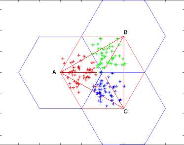
The proposed algorithm considers the common scenario of three facing sectors in cellular network, shown in Fig. 2. Assume that a scheduling period is partitioned into several slots and in each slot only a single beam is used in each sector. Each beam may have different transmitted power at the different slot, but the average transmitted power of each beam in a scheduling period is fixed. There are direct exchange interfaces among sectors in the cooperation area. Hence each sector can pass information of users to neighbors by the interfaces, such as channel gain and user’s locations.
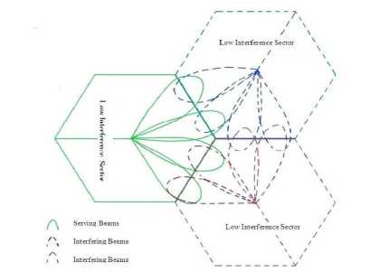
Figure 2. Three facing sectors in the coordination area
At the beginning of a scheduling period, each sector in the coordination area executes the scheduling algorithm based on the exchanged channel information with adjacent sectors through the X2 interface, so as to independently calculate the applied order and transmitted power of the beams. When all beams have been transmitted, a new scheduling period starts.
This scheduling problem is modeled as a constrained optimization problem. For an cooperation area, let A , B , C denote three facing sectors and each sector can use one of N beams in each slot. Let N x 1 vectors t A , t B , t C denote the applied order of beams according with above sectors and pA,p B ,pC denote the transmitted power of beams respectively in a scheduling period.
Because users’ locations are known, angles between users and each beam can be calculated. Let e km denote the angle between user k and beam m in sector A , so the channel gain of user k in sector A can be shown as follow [8].
s ° * g ° A * a ( e k m )
L ( d k A )
G
A k . m
Where S 0 A denotes the shadow fading and G 0 A captures the combined gain of the noise, the cable loss and the penetration loss. a ( e Am ) is the antenna gain of user k when sector A uses beam m and L ( d k A ) accounts for the path loss of user k [9]. Similarly calculate GkB , n and GkC , l , which denote the channel gain of user k in other sectors.
For a given applied order and transmitted power of beam, the sum throughput of cooperation area in a slot can be obtained as follow.
First, calculate the SINR of the users based on the channel gain reported by each user. In slot n , when sector A using beam t A ( n ) , sector B using beam t B ( n ) and sector
C using beam t C ( n ) , only S users locating in beam t A ( n ) can be served if just consider sector A . The SINR of user k is such that
SINR k ( n ) =
_______________ Pa ( n ) ■ G kAn _______________ No ■ " + P b ( n ) ■ G kBn + P c ( n ) ■ GL
where No is the power spectral density of noise and w is the bandwidth of a single resource (e.g. one carrier of a cluster of several carriers).
Assume that the S users located in beam tA (n) use the max C/I allocation algorithm [10] to share totally Q resources in sector A and each user have enough data to occupy the allocated resources. The number of resources allocated to user k is xk(n) = Slog,(1 + SINRk(n)) * Q (9)
Z log e (1 + SINR k ( n ))
k = 1
Based on the SINR of all users and the allocated resource number, the throughput of sector A in slot n is
F a ( n ) = Z log e (1 + SINR k ( n ))* x k ( n ) (10)
k = 1
Similarly calculate the throughput of sector B , C respectively in slot n and finally the total throughput of the cooperation area in a scheduling period is the function of the applied order t A , t B , t C and the transmitted power p A , p B , p C .
F (t A- t в- t C- P a- P B- P C ) = Z [Fa ( n )+ Fb ( n ) + Fc ( n )]
n = 1
The optimal applied order and transmitted power of the beams can be obtained by maximize the above function.
{tA ■tB-tC ,pA .pB ,pC }=arg max F (ta-t в-tc-pa-p в-pc )
s.t.
NNN
-
-1-Z Pa (i) 5 Pa ; Z Pb (i) ^ Pb ; Z Pc V) ^ P;
N i=1 N i=1
Pa (i) г 0; Pb (‘)2 °: Pc (i)2 °1 i = 1,2, ••• N ta, tв, tc e{1-2-N)
Equations (13)-(15) describe the practical constraints in reality communication system. Eq. (13) denotes that the average transmitted power of each beam is limited and (14) denotes the transmitted power of each beam cannot by negative. Eq. (15) implies that the applied order of beams is expressed by integer within 1 ~ N .
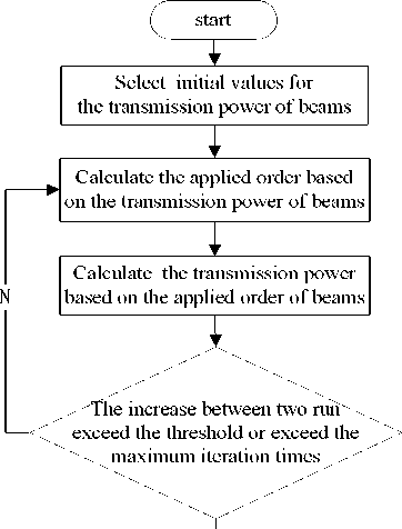
This constrained optimization model is a mixed programming problem, because t A , t B , t C is integer describing the applied order of beams and p A , p B , p C is real numbers describing the transmitted power of beams. This problem is difficult to solve directly, so we propose an iterative approach that split it into an integer programming problem for applied order and a nonlinear programming problem for transmitted power. The detail is shown as follow.
Step 1: Initialization.
Assume the beams have identical power. Calculate the averaged power as the initial values of p A , p B , p C . Set the total throughput of cooperation area’s initial value as 0.
Step 2: Beam Scheduling.
Based on the values of p A , p B , p C , calculate the optimal solution of t A , t B , t C . This is an integer programming problem. Because the values of t A , t B , t C are limited, we can use exhaustive searching.
Step 3: Power Scheduling.
Based on the current values of t A , t B , t C , obtain the optimal solution of p A , p B , p C . This is an optimization problem of continuous differentiable function and we can use the classic gradient descent method to solve it.
Step 4: Convergence Evaluation.
Calculate the total throughput of cooperation area based on optimal solutions of t A , t B , t C , p A , p B , p C obtained by step 2-3. If the difference of throughput between two adjacent iterations is less than a threshold then stop this iteration and output the final result, else go to step 2.
The flow of the proposed algorithm is illustrated in Fig.3.
Y
Figure 3. The flows of the proposed algorithm
-
IV. C OMPUTER S IMULATIONS
We assume there are 4 beams in each sector and the angle of two adjacent beams is exactly 30° (see Fig. 2). This simulation is based on 2MHz bandwidth and the frequency reuse factor is 1. The total transmitted power of each sector in a scheduling period is 43dBm and the power spectral density of noise is -174 dBm/Hz.
We will use a simplified model for the transmissions channel, not considering the frequency selective feature, just focus on channel gain shown in (7). Shadow fading is modeled as a log-Normal random variable with standard deviation of 8 dB and inter-sector correlation coefficient of 0.5. Loss factor G 0 is 0 dB [8]. Assume Shadow fading and Loss factor are identical in each sector. The antenna gain of user k , i.e., A ( θ k A , m ) is calculated as
A ( θ kA , m ) = - min(12*( θ kA , m )2, A m ) (16)
θ 3 dB
Because the angle of the beam is exactly 30°, the angle of antenna gain reduction to 3dB denoting θ 3 dB is 17.5° and the maximization of antenna gain A m is 20 dB.
The path loss of user k is calculated by
-500
-1000
-1500
-1000 -500 0 500 1000 1500 2000 2500
Figure 4. User distribution of sectors in scene 1
Number of Iterations
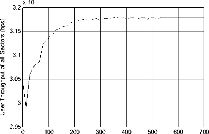
Figure 5. The convergence of beam-power coordinative scheduling algorithm in scene 1
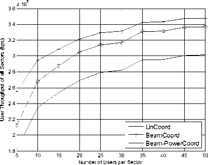
Figure 6. The sum throughput of cooperation area in scene 1
L ( d kA ) =128.1+37.6 log 10 ( d kA ) (17)
where dkA is the distance between user k and sector A .
We compare our proposed algorithm with the existing round robin beam servicing approach [4] and the approach that applies only beam cooperative scheduling [1] in three simulation scenes.
First we consider the scenario where the users approximately have uniform distribution; Fig.4 illustrates the common scenario of three facing sectors in the cellular network where there are maximally 50 users in each sector.
Fig.5 illustrates the convergence curse of the total throughput of scene 1, where the user number is 50. It can be observed the algorithm converge after 200 iterations.
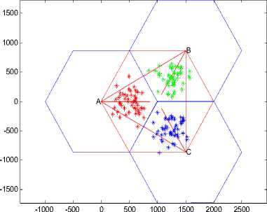
Figure 7. User distribution of sectors in scene 2
users around this hotspot obey the Gaussian distribution.
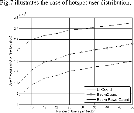
Figure 9. The sum throughput of cooperation area in scene 2
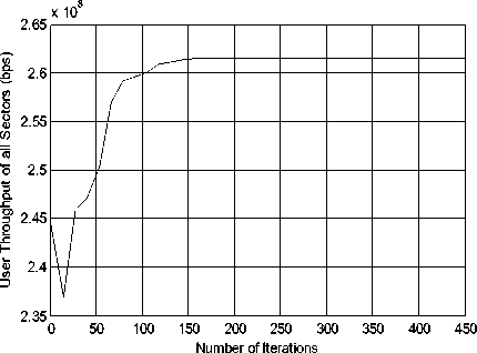
Figure 8. The convergence of beam-power coordinative scheduling algorithm in scene 2
Normalized Throughput
Figure 10. The CDF of normalized throughput of sector A in scene 2
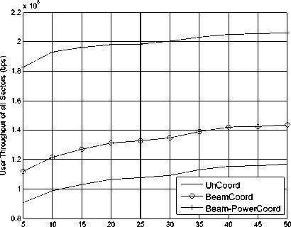
Fig.6 shows the corresponding sum throughput of cooperation area in the scene of approximate uniform user distribution where the number of users varies from 5 to 50 and the total number of resource 25 in each sector. As the number of users increases, the sum throughput of cooperation area increases at first and finally reaches a plateau in all three kinds of scheduling algorithm. The proposed algorithm outperform the other two algorithms, but the sum throughput gap of cooperation area between the joint beam-power coordinative scheduling algorithm and the approach that applies only beam cooperative scheduling is gradually becoming narrowing.
Computer simulation shows that the coordinative scheduling proposals both significantly outperform the existing round robin beam servicing approach, because cooperation scheduling can reduce the inter-sector interference. The joint beam-power coordinative scheduling proposal may adjust the transmitted power of the beams according to those serving users and the number of users in each beam is approximate uniform, hence the advantage of improving the power efficiency is not obvious.
Because the uniform user distribution is not common in a sector in actual network, next we consider the scene of hotspot user distribution. Each sector has a hotspot and all where there are 50 users in a sector.
In fig.8 we plot the corresponding convergence of beam-power coordinative scheduling algorithm in the scene of hotspot user distribution. Compared with fig.5, the convergence of approach is most smooth in this user distribution. When the number of iterations is 150, the sum throughput of cooperation area begins to converge.
In fig.9 we plot the sum throughput of cooperation area in the scene of hotspot user distribution where simulation conditions are same with the scene of approximate uniform user distribution.
Compared with fig.6, the trend of sum throughput over the cooperation area that increases at first and finally reaches a plateau is as same as scene 1. In case where there is a hotspot in the coverage area, the advantage of the joint beam-power scheduling is more significant.
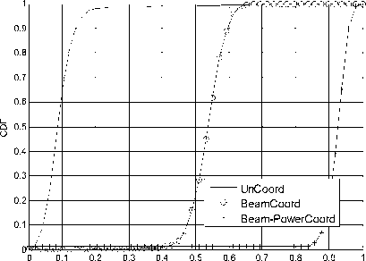
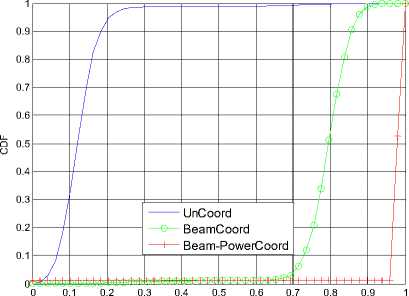
Fig.10 illustrates the cumulative distribution function (CDF) of normalized throughput of sector A in this scene. The joint beam-power coordinative scheduling algorithm significantly outperforms other algorithms in improving the performance of edge user.
Computer simulation shows that the joint beam-power coordinative scheduling algorithm perform best in the scene of hotspot user distribution, because it not only avoid the adjacent beam collision but also improve the utilization of power resource by dynamically changing the transmitted power according to the users distribution.
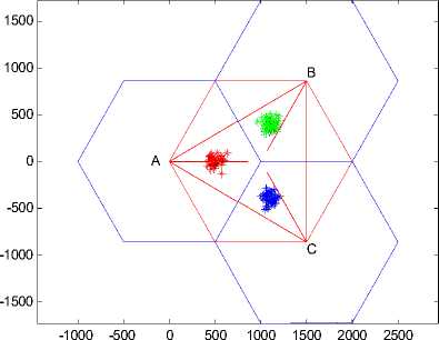
Figure11. User distribution of sectors in scene 3

Figure12. The convergence of beam-power coordinative scheduling algorithm in scene 3
In order to further highlight the advantage of the joint beam-power coordinative scheduling algorithm, we compare three algorithms in the scene of extreme hotspot user distribution. There are 50 users located in a particularly small area in each sector, shown in fig.11.
The convergence of the total throughput is plotted in fig.12. It can be observed the proposed algorithm achieve fast convergence speed in scene 3.
The sum throughput of cooperation area in the scene of special hotspot user distribution is illustrated in fig.13. Compared with fig.6 and fig.9, the trend of sum throughput over the cooperation area is as same as those above user distributions, but the value of sum throughput totally decreases in all three kinds of scheduling algorithm. In this scene that users are located too centralized in one or two beam and each beam could be chosen only once in each period to keep the fairness of beams, so the sum throughput of cooperation area is lower than other user distributions. In the previous we assumed that the beam set are fixed that cover the whole sector, if we reset the beam sets at the beginning of the scheduling period according to information such as the channel gain and user’s locations which users respond to sectors, this problem could be resolved easily.
Number of Users per Sector
Figure 13. The sum throughput of cooperation area in scene 3
Normalized Throughput
Figure 14. The CDF of normalized throughput of sector A in scene 3
Although the sum throughput of cooperation area in three kind algorithms totally reduce, but the gap between the joint beam-power coordinative scheduling algorithm and the approach that applies only beam cooperative scheduling is significant greater. It means that as the user concentration increased, the joint beam-power coordinative scheduling algorithm performs better. The scene of extreme hotspot user distribution is rare in practice, but it is a good way to measure the performance of algorithms.
In fig.14 we correspondingly plot the CDF of normalized throughput of sector A . Computer simulation further shows that the joint beam-power coordinative scheduling algorithm performs best; the existing round robin beam servicing approach performs worst in the scene of extreme hotspot user distribution.
-
V. C ONCLUSION
A new joint beam-power scheduling algorithm has been proposed in this paper. In the new algorithm the power of each beam was adjusted based on its serving users. Simulation results show that the propose algorithm can significantly improve the utilization of power resource and maximize the system throughput. Moreover, when users are more intensively allocated in a hotspot, more improvements of system throughput can be observed.
References Semi-Distributed Coordinative Switch Beamforming with Power Scheduling
- Patrick Hosein, “Cooperative Scheduling of Downlink Beam Transmissions in a Cellular Network,” GLOBECOM Workshops 2008 IEEE, Dec 2008.
- Stefania sesa, et.al, “LTE-the UMTS Long Term Evolution: fromtheory to practice,” UK:A John Wiley and Sons, Ltd, Publication, 2009, pp.285-299.
- Wangtong, Weigao, “The application of Bulter multi-beam matrix in TD-SCDMA system. Electronic technology applications,” China, August 2005, pp55-56
- T.Kuze,et.al,“Analogue Beamforming. IEEE 802.16 Broadband Wireless Access Working Group,” Contribution No. IEEE C802.16m-08/438, May 2007.
- 3GPP,R1-084352, HuaWei, “Some Results on DL coordinated beam switching for interference management in LTE- Advanced,” Nov 2008.
- Chenxiang, Xiaolimin, et.al, “a muti-antenna coordinative scheduling among cells in cellular communication system,” China, 200910077815.9, petent, Feb 2009.
- P. Hosein, “On the Optimal Allocation of Downlink Resources in OFDM-Based Wireless Networks,” Lecture Notes in Computer Science, vol.3970/2006, Ch. 15
- Honghai Zhang,et.al, “Distributed inter-cell interference mitigation OFDMA wireless data networks,” GLOBECOM Workshops 2008 IEEE, Dec.2008.
- Long Term Evolution(LTE): Overview of LTE Air-interface Technical White Paper: Motorola. http://business.motorola.com/experiencelte/ pdf/LTEAirInterfaceWhitePaper.pdf
- Zhouyuan, “the downlink scheduling algorithm in MAC layer in LTE syetem,” Xian, China, Xian university of electronic science and technology, 2009 .
- P. Viswanath, D. Tse, and R. Laroia, “Opportunistic beamforming using dumb antennas,” IEEE Trans. Inform. Theory, vol. 48, pp. 1277–1294, June 2002.
- Cornelius van Rensburg, Wylie, et.al, “ System and method for synchronized and coordination beam switching and schduling in a wireless communication system,” US2010/0033374 A1, 2010
- Wang Xiaoyong, Xiao Dengkun, Jing Xiaojun, “A norvel power allocation algorithm under CoMP with CA,” Huawei Technologies Co., Ltd Beijing University of Posts and Telecommunications
- 3GPP TR 25.814, “3rd Generation Partnership Project; Technical Specification Group Radio Access Network; Physical Layer Aspects for Evolved UTRA (Release 7)”
- M. Pun, V. Koivunen and H. Vincent Poor, “Opportunistic scheduling and beamforming for MIMO-SDMA downlink systems with linearcombining”, Proc. PIMRC 2007, Athens, Sept. 2007.
- IEEE standard for local and metropolitan area networks part 16: Air interface for fixed and mobile broadband wireless access systems,” in IEEE Std 802.16e, 2005.
- 3GPP, R1-070099, NTT DoCoMo, “Frequency Domain Channel Dependent Scheduling Considering Interference to Neighboring Cell for EUTRA Uplink,” Jan 2007.
- Ericsson, R1-062282, “Schedule single vs. multiple beams per frame for E-UTRA”, Tallin, Estonia, August 28–September 1, 2006.
- Huawei, R1-083236, “Coordinated Beam Switching for Interference management in Advanced E-UTRA”, JeJu, Korea, Aug 18 – 22, 2008.
- Samsung, R1-082886, “Inter-Cell Interference Mitigation Through Limited Coordination”, JeJu, Korea, Aug 18 – 22, 2008.
- Alcatel-Lucent, R1-081874,“Support for Semi-Static Inter cell Interference Coordination”, Nortel Networks, may 2008.
