Semi-Physical Simulation of RR/S Attitude Algorithm Based on Non-Holonomic IMU

Author: Zhong Su,Guodong Fu,Qing Li
Journal: International Journal of Computer Network and Information Security(IJCNIS) @ijcnis
Article in issue: 1 vol.1, 2009.
Free access
Rolling Rocket/Shell (RR/S) can effectively overcome the impact point error caused by the asymmetry of aerodynamic appearance and mass eccentricity .etc. The spatial attitude of RR/S in the process of flight must be studied for that RR/S realizes the guidance control and improves the falling point precision. This paper introduces a semi physical simulation of RR/S attitude algorithm based on non-holonomic Inertial Measurement Unit (IMU) which is composed of 3 orthogonal import rate gyroscopes. It adopts the 902E-1 two-axis turntable to simulate the spatial attitude of RR/S, and uses the non-holonomic IMU, which is fixed on the turntable by ensuring the axes of them to be aimed, to measure the 3-axis angular rate motion of the turntable. By setting the motion condition of the turntable, we can get the 3-axis angular rate data of the IMU and the 3-axis angular position data of the turntable. The attitude algorithm simulation of IMU adopts the four-sample rotation vector algorithm based on MTLAB/Simulink. The simulation results show that the semi-physical simulation method can model the spatial attitude of RR/S truly and provide exact and real-time attitude information of RR/S which is rolling in the two-axis complex movement condition.
Rolling Rocket/Shell (RR/S), non-holonomic IMU, 902E-1 two-axis turntable, first term, four-sample rotation vector algorithm, second term, third term, fourth term, fifth term, semi-physical simulation
Short address: https://sciup.org/15010975
IDR: 15010975
Text of the scientific article Semi-Physical Simulation of RR/S Attitude Algorithm Based on Non-Holonomic IMU
Published Online October 2009 in MECS
Rolling Rocket/Shell (RR/S) is rolling about on its longigudinal axis at a high roll rate. For it can overcome the falling point deviation caused by asymmetry of aerodynamic appearance and mass eccentricity, etc, RR/S is widely applied to army weapon equipment at home and abroad [1]. Now it has been an important firepower suppression instrument. But at the same time, owing to the trajectory affected by the factors of the launcher inclination, the initial disturbance and the atmospheric
Manuscript received January 3, 2009; revised June 11, 2009; accepted July 8, 2009.
This work is supported by the ‘Funding Project for Academic Human Resources Development in Institution of Higher Learning Under the Jurisdiction of Beijing Municipality’ (PHR200906131) and the ‘ Science and Technology Development Project of Beijing Haidian’(K20090037)
environment, etc, the traditional unguided RR/S has disadvantages of firing accuracy and falling density.
With the technique development sensor, inertial navigation, computer and simulation, etc, has become the urgent demand that RR/S realizes the guidance control. And compared with other navigation technology, the inertial navigation is an independent system which won’t bring electromagnetic radiation and be affected by light or electricity of outside environment. Considering the application condition, we use a non-holonomic IMU which is composed of 3 orthogonal import rate gyroscopes as the navigation equipment of the RR/S.
For that RR/S realizes the guidance control, we must research the spatial attitude of RR/S [2]. As we know, it is very costly to get the data of the attitude by launch examination. In this paper, we use 902E-1 two-axis turntable to simulate the spatial attitude of RR/S and use IMU which will be used on the RR/S to measure the 3-axis angular rate of the turntable. By comparing the output data of the turntable and the IMU, we can validate whether the performance of the IMU satisfies the attitude algorithm demand of RR/S. This semi-physical simulation can assure the credibility and the objectivity of the conclusion [3].
-
II. R EFERENCE F RAMES
Before describing the attitude algorithm principle, some reference frames that will be used in the paper are needed to be described.
-
A. Launch Reference Frame F t (Oxt ytzt )
In the launch reference frame the origin is at the launch position. The Oyt axis is the plumb line of the launch position and points up. The Oxt axis is perpendicular to the Oyt axis and points the launch direction. We define the plane which is composed of Oxt and Oyt axes as the launch plane. The Ozt axis and the other axes satisfy the right hand right-angle frame.
-
B. Navigation Reference Frame F n (Oxnynzn )
For the launch distance of RR/S is usually shorter and the factor of the earth rotation can be neglected, we use the launch reference frame as the navigation reference frame in this paper.
-
C. Body Reference Frame F b (Oxbybzb )
In the body reference frame, the origin is at the RR/S center of mass, while the Oxb axis points forward through the head of the body and is superposition with vertical-axis of the body. The Oyb axis is located in the vertical plane containing the body, and perpendicular to the Oxb axis. The Oz b axis and the other axes satisfy the right hand right-angle frame.
-
D. Attitude Description of RR/S
The real-time spatial attitude of RR/S can be ascertained by the relation between the navigation reference frame and the body reference frame. We make the origins of the two frames superposition, transform navigation reference frame three times, and we can get the spatial attitude of RR/S by three Euler angles which are rotation angle / , pitch angle 9 and yaw angle ф . The frame transformation is shown as Fig. 1.
-
Y - Rotation angular rate in F n ;
9 - Pitch angular rate in F n ;
ф - Yaw angular rate in F n .
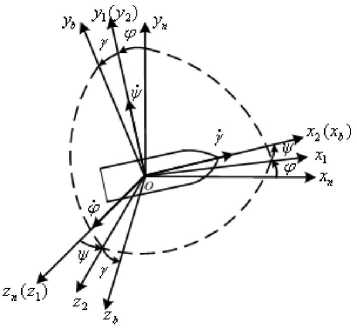
Figure 1. Frame transformation
-
III. A TTITUDE A LGORITHM P RINCIPLE
The non-holonomic IMU is fixed on the turntable with the condition of the axes of IMU and the turntable which are assured to be aimed by a tool. When the turntable is rolling or swaying, the 3-axes angular rate output in the body frame of IMU at t time is:
to (t) = (tox (t) toy (t) toz
The sampling time of data collection processing circuitry is h (ms). With the condition of algorithm precision and speed, we adopt the method of four-sample rotation vector algorithm. For the algorithm has smaller errors and quicker operation speed, it suits to be applied project algorithm [4][5].
Δ θi ( i =1, 2, 3, 4) is defined as the incremental angle output of gyros in the quarter of the sampling time h :
f t + i ■ h /4
to(T ) dT
Jt + ( i - 1) h /4
( i = 1,2,3,4)
For ω ( t ) is constant from t to ( t+h ), Δ θi ( i =1,2,3,4) can be changed into the following equation:
A9 1 = A 9 2 = A 9 3 = A 9 4 = A 9 = to ( t ) ■ 0.25 ■ h
The rotation vector Ф(h) from t to ( t+h ) is obtained as follows:
Ф ( h ) = A 9 1 + A 9 2 + A 9 3 + A 9 4
+ -315 ■ ( A 9 1 x A 9 2 + A 9 3 x A 9 4 )
+ юз* ■ ( A 9 1 x A 9 3 + A 9 2 x A 9 4 )
54 „ 214„
+--A 9 xA 9 +--A 9 xA 9
105 1 4 315 23
428 92 54214
= 4 A 9 + (--- +---+---+--- ) -A9xA9
315 105 105315
I ф ( h )=^ ф ( h ) 2 +ф ( h ) 2 +ф ( h ) 2
Using (4) and (5), the attitude transformation quaternion q ( h ) can be obtained as follows:
q ( h ) =
v
q 1( h ) q 2( h ) q 3( h ) q 4( h )
X
cos ^( h ) 1
cos
Ф ( h ) x nlф< h >l
| Ф( h )|sm 2
ф ( h ) , . Ф( h )
| Ф( h )|S”’ 2
ф ( 5 Ъс sin tl h ) (|Ф ( h ) 2 7
Using (6), the quaternion Q (t+h) at time (t+h) is given derived by the quaternion Q(t) at time t as follows:
Q ( t + h ) = Q ( t ) ® q ( h )
|
^ q 1 ( h ) |
- q 2 ( h ) |
- q з ( h ) |
- q 4 ( h )л |
^ q i( t ) |
|
q 2 ( h ) |
q 1 ( h ) |
q 4( h ) |
- q з ( h ) |
q 2 ( t ) |
|
q з ( h ) |
- q 4 ( h ) |
q 1 ( h ) |
q 2 ( h ) |
q з ( t ) |
|
V q 4 ( h ) |
q 3 ( h ) |
- q 2 ( h ) |
q i ( h ) 7 |
V q 4 ( t ) 7 |
|
(7) |
The Q (t+h) must be unitarily processed:
Q ( t + h ) =
Q ( t )
■^q 1 ( t + h )2 + q 2 ( t + h )2 + q 3 ( t + h )2 + q 4 ( t + h )2
With the condition of the simulation in this paper, the quaternion: Q (0) = ( 1 0 0 0 ) . Using (1) ~ (8) and Q
(0), we can calculate the real-time attitude quaternion Q (t+h), and we can get the key element of the attitude matrix as follows:
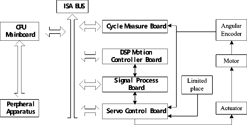
Figure 2. Control principle of the turntable
T ( t + h ) 11 = q 1 (t + h )2 + q 2( t + h )2 - q 3( t + h )2 - q 4 ( t + h )2 T ( t + h ) 21 = 2( q 2( t + h ) • q 3( t + h ) + q 1( t + h ) • q 4( t + h ))
■ T ( t + h ) 31 = 2 ( q 2( t + h )• q 4( t + h ) - q 1( t + h ) • q 3( t + h)) (
T ( t + h )32 = 2( q 3( t + h ) • q 4( t + h ) + q 1 ( t + h ) • q 2( t + h )) T ( t + h ) зз = q 1 ( t + h ) — q 2 ( t + h ) — q з ( t + h ) + q 4 ( t + h )
And the real-time attitude angular can be obtained by:
Pitch angle: 6 ( t + h ) = arctg ( ^( t + ^)21 )
g
T ( t + h Ju
Yaw angle: ф ( t + h )= arcsin(- T ( t + h )31)
Rotation angle:
system which is a double closed loop control system adopts an angular encoder as the feedback component of the angular position and the angular rate.
The encoder exports a quadrate pulse signal and a reference signal, which relate to the angular displacement of the turntable, to the DSP motion controller. The increment angular position which is decoded by the quadrate pulse signal is compared with the command signal. The error which is processed by the digital PID filter is converted to the emendation signal by the D/A circuit. The signal process forms an angular position closed loop control system. The angular rate signal which is processed exports to the servo control circuit and it forms an angular rate closed loop control system. The control principle is shown as Fig. 2.
/ ( t + h ) = <
arctg ( T ( t + h ) 3 2 ) T 33 > 0 & T 32 - 0 T ( t + h )33
arctg ( T ( t + h ) 32 ) + 360 T 33 > 0 & K. < 0
T ( t + h )33 33 32
arctg ( ^(f + ^)32 ) + 180 T 33< 0
T (t + h V 33
90 T 33 = 0& T 32 - 0
270 T 33 = 0& T 32 < 0
IV. 902E-1 T WO - AXIS T URNTABLE
902E-1 two-axis turntable is composed of a mechanical bed and an electrical control system. The turntable is a digital servo control system, which adopts DSP motion controller to a real-time control and adopts embedded computer to a motion control. The minimum system requirement is Windows 2000.
The mechanical bed is composed of a T-structure chief axis and a U-structure pitch axis which can be used to calibrate the north reference. The electrical control
TABLE I. K EY T ECHNOLOGY P ARAMETER F OR 902E-1
|
Performance |
Parameter |
|
|
Chief Axis |
Angular Position Range |
0~±360° |
|
Wobble Error |
±5″ |
|
|
Angular Rate Range |
0~±3600°/s |
|
|
Angular Acceleration Range |
0~±360°/s2 |
|
|
Angular Rate Precision |
1×10⁻⁴ |
|
|
Angular Rate Smoothness |
1×10⁻⁴ |
|
|
Pitch Axis |
Angular Position Range |
0~±190° |
|
Wobble Error |
±5″ |
|
|
Angular Position Precision |
±15″ |
|
|
Angular Position Repeatability |
±3″ |
|
|
Angular Rate Range |
0~±100°/s |
|
|
Angular Acceleration Range |
0~±200°/s2 |
|
|
Swaying Frequency Range |
0~3Hz |
|
|
Swaying Amplitude Range |
0~180° |
|
|
Swaying Amplitude Error |
≤ 5% |
|
|
Swaying Wave Distortion |
≤ 5% |
|
|
Swaying Axis Drift |
± 0.02°/h |
|
|
Verticality Between Chief and Pitch Axes |
±5″ |
|
|
Flatness |
0.01mm |
|
|
Side Face Run-out |
0.01mm ( Φ 180mm) |
|
|
Table-board Diameter |
240mm |
|
-
V. N ON - HOLONOMIC I NERTIAL M EASUREMENT U NIT
Inertial Measurement Unit has the excellence of high precision, small volume, low cost and disturbance proof. The non-holonomic IMU can measure the 3-axis angular rate of RR/S in the body frame by fixing the inertial sense organs (gyroscopes) in the body of RR/S. Then calculating by computer plat, the system can detect and give a real-time attitude angle deviation of RR/S. The control circuit changes the deviation signal into attitude control signal which can control the attitude engine work and improve the RR/S falling point precision.
In this paper, we use the XJGZ-3 IMU which is produced by Beijing SinsTek Corporation Ltd. The XJGZ-3 is consisted by a static piezoelectric gyroscope, two MEMS gyroscopes and data collection processing circuitry, with the characters that widely measured range low cost and small volume, applying to measure RR/S’s 3-axis angular rate attitude. The key technology parameter is shown in Table 2.
-
VI. S IMULATION
-
A. Algorithm Simulation Flow
We use MTLAB as the software simulation tool. The MTLAB provides a high-level programming language, an interactive technical computing environment, and functions for: algorithm development, Data analysis and visualization, Numeric computation .
The name MATLAB stands for matrix laboratory. MATLAB was originally written to provide easy access to matrix software developed by the LINPACK and EISPACK projects. Today, MATLAB engines incorporate the LAPACK and BLAS libraries, embedding the state of the art in software for matrix computation.
Simulink is a software package for modeling, simulating, and analyzing dynamic system. It supports linear and nonlinear systems, modeled in continuous time, sampled time, or a hybrid of the two. Systems can also have different parts which are sampled or updated at different rates.
After defining a model, we can simulate it, using a choice of integration methods, either from the Simulink menus or by entering commands in the MATLAB Command Window. The menus are particularly convenient for interactive work, while the command-line approach is very useful for running a batch of simulations. Using scopes and other display blocks, the results can be read while the simulation is running. In addition, many parameters can be changed and see what happens for "what if" exploration. The simulation results can be put in the MATLAB workspace for post processing and visualization. Model analysis tools include linearization and trimming tools, which can be accessed from the MATLAB command line, plus the many tools in MATLAB and its application toolboxes. And because MATLAB and Simulink are integrated, which make it is able to simulate, analyze, and revise models in either environment at any point. Before describing the attitude algorithm principle, some reference frames that will be used in the paper are needed to be described [7].
The simulation flow is shown as Fig. 3.
TABLE II. K EY T ECHNOLOGY P ARAMETER F OR XJGZ-3
|
Performance |
Parameter |
|
|
Longigudinal Axis |
Gyro Input Range (°/s) |
0~3600 |
|
Nonlinearity (F.S) |
5×10⁻⁴ |
|
|
Resolution (°/s) |
1 |
|
|
Gyro Bias (°/s) (1σ) |
0.01 |
|
|
Drift (°/s) |
0.1 |
|
|
Yaw and Pitch Axis: |
Gyro Input Range (°/s) |
0~±30 |
|
Nonlinearity (F.S) |
1×10⁻³ |
|
|
Resolution (°/s) |
0.5 |
|
|
Gyro Bias (°/s) (1σ) |
0.01 |
|
|
Drift (°/s) |
0.007 |
|
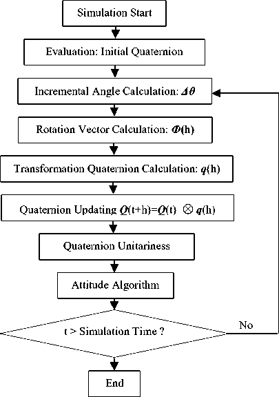
Figure 3. MTLAB simulation flow
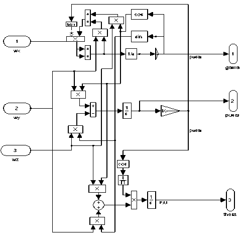
Figure 4. Mathematical simulation
-
2) Mathematical Simulation Results
We set that the IMU is fixed on the turntable as follows: The Oxb axis of the IMU is consistent with the
-
B. Mathematical Simulation
-
1) Input Conditon
The input condition of the mathematical simulation must simulate the motion of the turntable truly. According to the working condition of the turntable, we can ascertain the turntable motion equation as follows.
The chief axis angular rate motion equation is:
mc=360-n (°/s) n=l,2-9,10
The pitch axis angular rate motion equation is: top = A • to ■ (cos tot) (°/s)
While n is the rev of the chief axis, A is the amplitude of the pitch axis, and ω is the frequency of the pitch axis.
When the turntable is swaying about its pitch
(11) swaying swaying
axis, it is
rolling about its chief axis. The ω yb and ω zb which are the output of the non-holonomic IMU fixed on the turntable can be obtained by the component of the ω p in Oyb and Oz b axes in the body reference frame. The ω xb which is the output of the non-holonomic IMU is the ω c The input condition of the mathematical simulation is shown as follows:
chief axis of the turntable, and the O z b axis of the IMU is consistent with the pitch axis of the turntable. According to (12), we set the mathematical simulation input condition as follows:
(1) n = 0, A = 5°, f = 1Hz, simulation time: 10s;
(2) n = 10, A = 30°, f = 0.4Hz, simulation time: 10s;
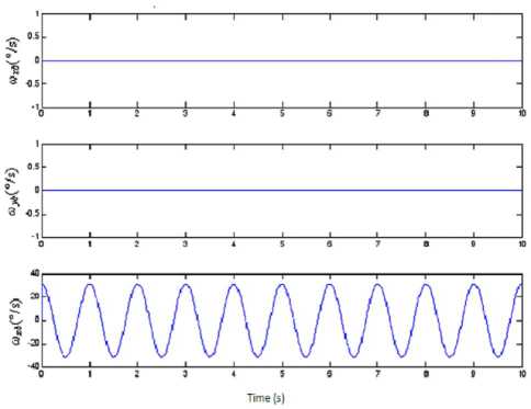
Figure 5. 3-axes angular rate mathematical simulation data of the IMU in condition (1)
toxb=360-n toyb=A-to- cos tot -sin у tozb=A-to- cos cot • cos у
Using (12) and the attitude algorithm principle, we can get the real-time spatial attitude of RR/S in the complex motion which is composed of the rolling and swaying motion.
The mathematical simulation is designed as in Fig. 4.

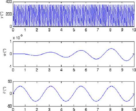
Figure 6. Attitude angular mathematical simulation data of the IMU in condition (1)
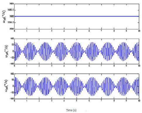
Figure 7. 3-axes angular rate mathematical simulation data of the IMU in condition (2)
The mathematical simulation results are shown in Fig. 5 ~ Fig. 8. The results prove that if the measurement errors of the gyroscopes can be neglected, when we change the rolling angular rate of the RR/S, the swaying amplitude and the swaying frequency of the RR/S, there is some angle error in the real-time yaw angle. And due to the calculation error, the error increases with time. In 10s, it is about 1 ‰ °, and we consider that it can satisfy the requirement of the system.
-
C. Semi-Physical Simulation
The IMU is fixed on the turntable as follows: The Oxb axis of the IMU is consistent with the chief axis of the turntable, and the Ozb axis of the IMU is consistent with the pitch axis of the turntable.
The turntable motion condition is:
-
(1) The chief axis is rolling at 360°/s; the pitch axis is swaying at 0.5Hz, and the swaying amplitude is 0.5°.
-
(2) The chief axis is rolling at 720°/s; the pitch axis is swaying at 1Hz, and the swaying amplitude is 0.5°.
-
(3) The chief axis is rolling at 2520°/s; the pitch axis is swaying at 1Hz, and the swaying amplitude is 2.5°.
-
(4) The chief axis is rolling at 3600°/s; the pitch axis is swinging 5°.
The output of the turntable and the simulation results of the IMU are shown in Fig. 9 ~ Fig.16 as follows:
Time (s)
Figure 8. Attitude angular mathematical simulation data of the IMU in condition (2)
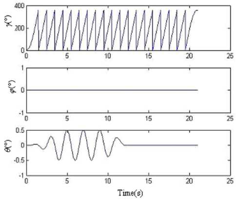
Figure 9. 3-axis angular position data of the turntable in condition (1)
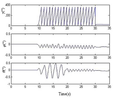
Figure 10. Simulation results of four-sample rotation vector algorithm based on the output data of IMU in condition (1)
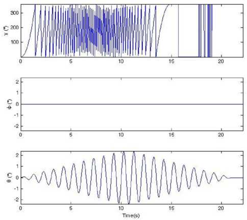
Figure 13. 3-axis angular position data of the turntable in condition (3)
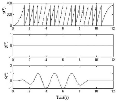
Figure 11. 3-axis angular position data of the turntable in condition (2)
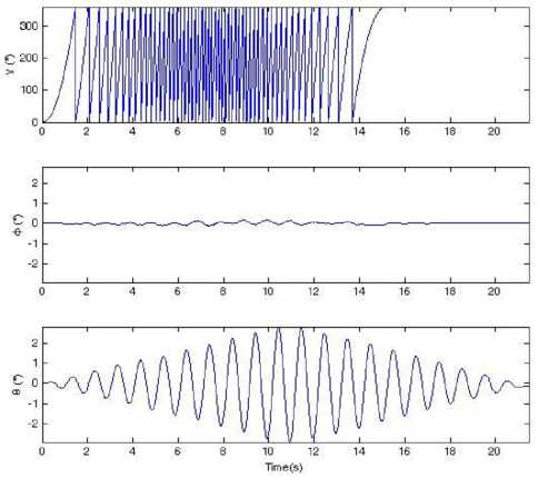
Figure 14. Simulation results of four-sample rotation vector algorithm based on the output data of IMU in condition (3)
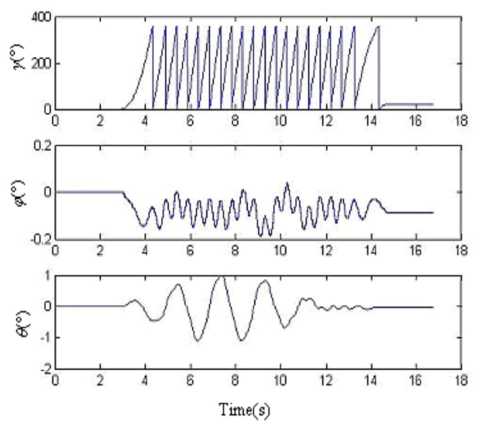
Figure 12. Simulation results of four-sample rotation vector algorithm based on the output data of IMU in condition (2)
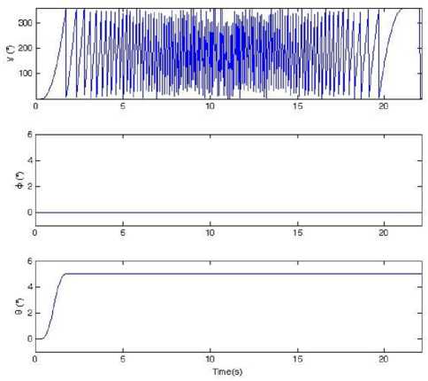
Figure 15. 3-axis angular position data of the turntable in condition (4)
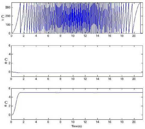
Figure 16. Simulation results of four-sample rotation vector algorithm based on the output data of IMU in condition (4)
The semi-physical simulation results prove that when the RR/S simulates the complex motion, which is composed of the rolling and swaying motion, according to the attitude algorithm principle in this paper, we can obtain the right real-time spatial attitude angles. There is some large error in the results. For there is cross-coupling error when the IMU is fixed on the turntable, and the gyroscopes have stochastic shifting error and nonlinear error, when the turntable is rolling as a high angular rate, the swaying motion will take some error in the pitch angle and yaw angle. How to improve the accuracy will be studied in the future.
-
[4] Yong-yuan Qin, “Inertial Navigation,” Beijing: Science Press, pp.305-317, 2006.
-
[5] Dohyoung Chung, Jang Gyu Lee, and Chan Gook Park, “Strap-down INS error model for multi-position alignment,” Aerospace and Electronic Systems, pp. 13621366, IEEE Transactions on Vol32, Oct. 1996.
-
[6] Yan-bo Li, Ming Zeng, “Influence of Three-axis Turntable Error Source on Pendulous Integrating Gyro Accelerometer Testing,” Aviation Precision Manufacturing Technology, pp. 28-31, Vol.44, No.2, Apr. 2008.
-
[7] Dong Li, Jin-jiang Liu, “Simulation and Realization of m Sequence Based on MATLAB,” Journal of Chongqing Institute of Technology (Natural Science), pp. 139-141, Vol.22, No.4, Apr. 2008.
Zhong. Su was born in 1962. He is currently a professor in Beijing Information Science & Technology University, Beijing 100101, China. He received his Ph.D. degree in physical electronics in 1998 from Sensor Research Institute, Beijing Institute of Information Technology, Beijing 100101, China. His research interests include inertial sensors and inertial navigation. He has authored and co-authored more than 60 papers in research journals and conference proceedings in these areas.
-
VII. C ONCLUSION
This paper introduced an effective way to make a semi-physical simulation of RR/S attitude algorithm. The semi-physical simulation results show that: the semiphysical simulation method can model the spatial attitude of RR/S truly. And this method can validate whether the performance of the IMU satisfies the attitude algorithm demand of RR/S. Also it provides a way to compare the precision and calculation efficiency of different attitude algorithm.
A CKNOWLEDGMENT
The authors wish to thank Yali Xie and Ying Lin for their assistance in the implementation and testing of this system.
References Semi-Physical Simulation of RR/S Attitude Algorithm Based on Non-Holonomic IMU
- Zhen-yu Du, Geng-chen Shi, “Study on the measurement method of projectile attitude,” Journal of Detection & Control, pp.53-56, 2002, (1).
- Cheng Zhang, Shu-xing Yang, “A method to get the attitude of a rolling airframe missile,” Transactions of Beijing Institute of Technology, pp. 481-485, 2004, 24(6).
- Dong-cai Qu, Development of “Strap-down Inertial Navigation System and Its Military Application,” Subject Development, pp. 27-30, 2004.
- Yong-yuan Qin, “Inertial Navigation,” Beijing: Science Press, pp.305-317, 2006.
- Dohyoung Chung, Jang Gyu Lee, and Chan Gook Park, “Strap-down INS error model for multi-position alignment,” Aerospace and Electronic Systems, pp. 1362- 1366, IEEE Transactions on Vol32, Oct. 1996.
- Yan-bo Li, Ming Zeng, “Influence of Three-axis Turntable Error Source on Pendulous Integrating Gyro Accelerometer Testing,” Aviation Precision Manufacturing Technology, pp. 28-31, Vol.44, No.2, Apr. 2008.
- Dong Li, Jin-jiang Liu, “Simulation and Realization of m Sequence Based on MATLAB,” Journal of Chongqing Institute of Technology (Natural Science), pp. 139-141, Vol.22, No.4, Apr. 2008.
