Serial digital color image watermarking using composite scheme

Author: Dayanand.G.Savakar, Anand Ghuli
Journal: International Journal of Image, Graphics and Signal Processing @ijigsp
Article in issue: 11 vol.9, 2017.
Free access
Digital watermarking is one of the ways to have Copyright protection for digital information. The digital watermarking scheme used for watermark embedding has to satisfy robustness property to ensure the security of the secret information hidden. The scheme presented here will support the above said statement significantly. We propose here the scheme as composition of both blind and non-blind digital watermarking technique in a process of serial watermarking. A secret binary image is embedded in the first cover image to get first watermarked image by using blind watermarking technique. Then this first watermarked image is again embedded into second cover image to get serial watermarked image using non-blind watermarking technique. To extract secret binary image, first non-blind watermark extraction technique and then blind watermark extraction techniques are used. From this composite approach and serial watermark embedding procedure, we achieved considerable fidelity and robustness against - Rotation, JPEG compression and for noises Salt & pepper, Gaussian, Speckle, Poisson and multiple noises.
Composite scheme, Serial watermarking, First cover image, Second cover image, Serial watermarked image, Blind, Type-II Non-blind
Short address: https://sciup.org/15015916
IDR: 15015916 | DOI: 10.5815/ijigsp.2017.11.06
Text of the scientific article Serial digital color image watermarking using composite scheme
Published Online November 2017 in MECS
The Digital Image Watermarking is contributing significantly to copyright protection of Digital Image. The inherent characteristics of color image making a wealthy way to embed secret images as watermarks into it. The Digital Image Watermarking is quite a young field and grabbed a lot of attention of researchers. In relatively within a short span of time, significant and notable contributions have been observed in the field of Digital Image Watermarking with respect to theoretical and practical aspects. This potential area has the ability to address many security related issues like, copyright protection, usage monitoring, tracing of distribution and usage control [17][19]. However, in most of the digital watermarking schemas; robustness, fidelity, and capacity are the major properties to be addressed efficiently and convincingly [17][19]. This paper presents the scheme which will be another element in the synergy of contributing in the field of secured digital image watermarking. The watermarked image is an image with the secret watermark embedded into it. Then this watermarked image can be published, and the owner of the information can claim his ownership by retrieving the watermark hidden into it [17]. As a basic requirement, the watermarking scheme should be robust against various types of attacks on the image to be transmitted [17].
-
II. Related Work
Different types of transformations are used or being used with different watermark embedding / retrieving procedure and techniques to attain considerable robustness. In most of the cases discrete wavelet transformations (DWT) are used to decompose the image into the different set of frequency sub-bands like LL, LH, HL, HH to locate suitable area[13][14][18][23]. DWT, The Artificial bee colony and discrete cosine transformation in combination with various schemes used to attain robustness with respect to block based segmentation and others types of segmentation of cover image providing robustness to embed a watermark in accordance with the suitable embedding procedure [5][7][12][13][14]. The usage of fractional Krawtchouk transform (FrKT) in the digital image watermarking has given better robustness by using eigenvalue decomposition [1]. The scale invariant feature transform (SIFT) is used to extract high invariance feature points then by using non-sub sampled contourlet transform (NSCT) the watermark will be embedded using extracted features[2]. Learning based conventional neural network is also used for digital image watermarking, as it needs the knowledge of architecture and keys of embedding procedure, the intruder may feel difficulty in extracting watermark[4]. The various meta-heuristic techniques are used to achieve optimized performance [5]. The quaternion discrete Fourier transform used to get the maximum central region of the image and the watermark is embedded using magnitudes of low-frequency information [6]. SVD is used to embed the watermark into singular values of the obtained matrix form cover image [12]. Even the hybrid techniques like least significant bit plane and most significant bit planes are used in connection with DWT, SVD ABC to achieve good robustness and user specific threshold imperceptibility [10][11][12]. A non-blind approach based on DWT-SVD digital watermarking using Alpha Blending and Arnold transformation in YCbCr Color space is robust on geometric attacks [20]. A chaos based digital image watermarking algorithm based on redundant discrete wavelet transform (RDWT) and singular value decomposition (SVD) is used to achieve robustness [21]. RDWT is shift invariant and it improves the robustness against additive noise because of its redundancy. SVD is a complementary technique for watermarking schemes providing good stability and perceptual invisibility [21]. Instead of DWT, either complex wavelet transform(CWT), Multi wavelet or complex and rotated wavelet transform can be used to make the system more robust and secure [22].
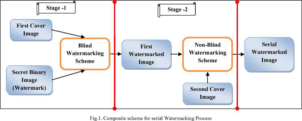
The scheme presented here is composed of two stages; stage-1 and stage-2. The stage-1 uses a blind watermarking technique to embed a secret binary image into a first cover image to get a first watermarked image. This first watermarked image again embedded into second cover image using a non-blind technique to get serial watermarked image. This whole process is depicted in Fig.1.
-
A. Composite scheme for serial watermark embedding
The composite scheme for serial watermark embedding uses the 2 level (Haar) Discrete Wavelet Transformation (DWT), 4×4 binary sequence block and Singular Value Decomposition (SVD). The terms used in proposed scheme are i) First Cover Image – The color image used to embed the secret binary image. ii) Secret binary image – watermark to be embedded into the first cover image. iii) First Watermarked Image – The color image embedded with a secret binary image. iv) Second Cover Image – The color image used to embed the First Watermarked Image. v) Serial Watermarked Image – The Second Cover Image embedded with First Watermarked Image. The following sections 2.1.1 to 2.1.3 describes the tools - DWT, Binary sequence block, SVD respectively and 2.1.4 to 2.1.5 describes how the tools are used in stage-1 and stage-2 of proposed scheme respectively.
A1 Discrete Wavelet Transformation (DWT)
The blind watermarking process of stage-1 uses DWT (Haar) to extract HL bands because HL bands will have very clear horizontal edges and are useful for locating the suitable area to embed secret binary image [14]. DWT decomposition will split the input signal into high-frequency and low-frequency parts. To analyze the high frequencies and low frequencies, the signal is passed through a series of high pass and low-pass filters respectively with different cutoff frequencies at different resolutions. To represent the DWT decomposition of a signal, consider the one-dimensional signal x[n] spanned in a frequency band of 0 to π radians. The signal x[n] is first passed through a high-pass filter g[n] and a low-pass filter h[n]. According to the Nyquist’s rule the half of the samples are eliminated, now the signal has the highest frequency of π/2 radians. The signal is sub sampled by 2 by discarding every second sample. This gives one level of decomposition of x[n] and expressed mathematically as equation (1) and (2).
-
Ум д н [к] = Х п Х[_к]д[2к - и] (1)
y i ow[k] = X n X[k]h[2k-n] (2)
where У^^^[к] and У/ои, [ к ] are the outputs of the respective high-pass and low-pass filters after subsampled by 2.
The above process can be repeated for further decomposition. The outputs of the high-pass and low-pass filters are called DWT coefficients and by these DWT coefficients, the signal can be easily reconstructed using the Inverse Discrete Wavelet Transform (IDWT). In Inverse Discrete Wavelet Transform (IDWT) the above process is followed in reverse order for the reconstruction. The signals at every level are upsampled by two and passed through the synthesis filters g'[n] and h'[n] (high-pass and low-pass, respectively) and added to produce the original signal. Mathematically IDWT can be expressed as follows:
жИ =’£умап[кАд[-п. + 2кА + ytow[kAh\-n + 2kA (3)
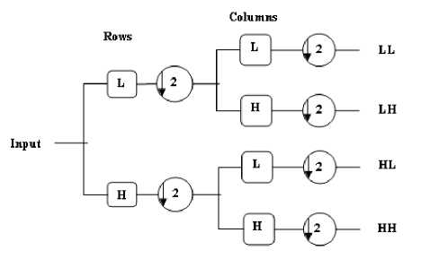
Fig.2. Wavelet Decomposition
|
LL |
HL |
HL |
|
HL |
HH |
|
|
LH |
HH |
|
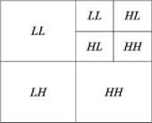
Fig.3. Wavelet Sub-band Representation
In an image processing application, the twodimensional wavelet is used. This will limit to only square images with the height and width equal to the power of two. If the image is of the size N × N then N = 2n. Fig.2 represents one level DWT decomposition of an image. The wavelet analysis is the application of high-pass and low-pass filters that separate the original image into four sub-images with the different frequency components. For an image of size N × N wavelet decomposition generates N2 wavelet coefficients. Fig.3 shows the steps used for one-level decomposition of an image. Initially, the image is passed through the high-pass and low-pass filters along the rows and the results of each filter are down-sampled by two. The two subsignals correspond to the high-pass and low-pass components along the rows are again passed through high-pass and low-pass filtered along the column. The results are again down-sampled by two. In this way, the original image is split into four sub-images each of size N/2 × N/2 which contains the different frequency components. This composition of frequency components is known as the inverse decomposition. Fig.4 represents one level inverse DWT.
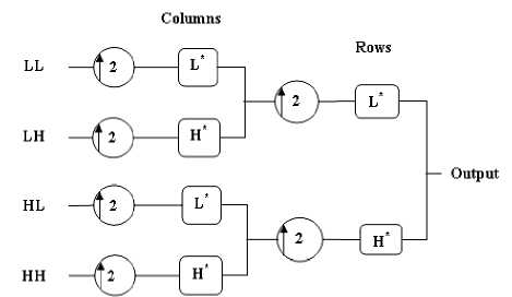
Fig.4. One level Inverse DWT
The two-dimensional wavelet transform can be seen as one-dimensional wavelet transform along the x and y axes. Mathematically the wavelet transform is convolution operation, which is equivalent to pass the pixel values of an image through a low-pass and high-pass filters. The wavelet transform of an image decomposes the image into four frequency bands, namely, the LL1, HL1, LH1 and HH1 bands. H and L denote the high-pass and low-pass filters respectively. The approximated image LL is obtained by low-pass filtering in both row and column directions. The detailed images,
LH, HL and HH contain the high- frequency components. To obtain the next coarse level of wavelet coefficients the subband LL1 is further decomposed and critically sampled. Similarly, LL2 will be used to obtain further decomposition. By decomposing, the approximated image at each level into four sub-images forms the pyramidal image tree. This results in two-level wavelet decomposition of the image.
A2 Pre-Processing of Secret Binary Image
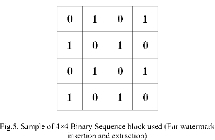
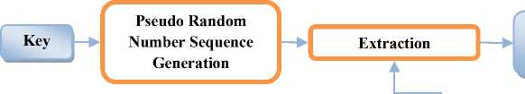
The secret binary image is converted into row matrix of sequences of 0s and 1s called secret binary image vector. To process HL2 sub-band block wise, the block structure is framed as shown in Fig.5. Now uniformly distributed random numbers are generated with the help of key image of size 1×35. Separate sequences of pseudo random numbers are formulated for 0s and 1s respectively known as pn_sequence_0 and pn_sequence_1.
A3 Singular Value Decomposition (SVD)
The singular value decomposition [12][18] of a m × n real or complex matrix A is a factorization of the form
A MxN = U MxM S MxN VT NxN (5)
Where
U T U = I MxM
V T V = I NxN (i.e. U and V are orthogonal)
Where U is a m×m real or complex unitary matrix, S is a m× n diagonal matrix with nonnegative real numbers on the diagonal, and VT is the conjugate transpose of V with a n × n real or complex unitary matrix. The diagonal entries S are known as the singular values of A. The m columns of U and the n columns of V are called the left singular vectors and right singular vectors of A, respectively. In singular value decomposition of an image, each singular value represents the luminance of image layer and the corresponding pair of the singular vector represents the geometry of the image layer [12][18]. The singular values in a digital image are less affected by general image processing operations because the bigger singular values preserve most energy of an image and resist against attacks. The singular values possess intrinsic algebraic image properties. In SVD-based image watermarking, several approaches are possible. A common method is to apply SVD to the entire cover image and to modify all the singular values to embed the watermark. But by applying SVD on DWT transformed sub-band images will improve robustness, because the important property of SVD based watermarking is that the modified singular values of an image will change by very small values for different types of attacks [12] [18]. The contents of these matrices are computationally stable and hence these are used in connection with DWT for more robustness.
A4 Stage-1 Watermark Embedding Process (Blind)
Fig.6 demonstrates Stage-1 of the composite watermarking scheme; the two level Haar wavelet decomposition is used on the input image to get four nonoverlapping multi-resolution sub-bands. To achieve acceptable performance with respect to imperceptibility and robustness it is found suitable to embed the watermark in the middle frequency sub-bands LHx and HLx [11]. Two level decomposed HL2 sub-band is considered for embedding the secret binary image into it by 4×4 block processing technique [14]. The inverse DWT is applied to reconstruct the original image with the secret binary image embedded into it [16].HL2 sub-band is scanned from left to right with the help of 4×4 binary sequence block. If secret binary image vector is 0 and content of the 4×4 binary sequence block is 1 then a constant gain factor is multiplied with pn_sequence_0 and added with the under scanning content of 4×4 HL2 block. If secret binary image vector is 1 and content of the 4×4 binary sequence block is 1 then a constant gain factor is multiplied with pn_sequence_1 and added with the under scanning content of 4×4 HL2 block. This whole process is depicted in Fig.6 and in Step.1 to Step.7 of Algorithm-1.
A5 Stage-2 Watermark Embedding Process (Non-Blind)
Stage-2 employs the non-blind watermarking technique, where the outcome of stage-1 is taken i.e first watermarked image to embed into second cover image. Here Haar single level DWT is applied on a second cover image to extract lower frequency LL sub-band where most of the image information (energy) is stored [14][16].
As the LL sub-band contains a lot of image information embedding the watermark may degrade the image significantly. So this LL sub-band image is divided into red (R), green (G) and blue (B) channels and singular value decomposition (SVD) is applied to each component to get computationally sustainable components as U, S and V matrices of the transformed image. The Same process is applied for the second cover image also.
Fig.7 demonstrates Stage-2 watermarking scheme. The combining function shown in the Fig.7 is framed such that S components of DWT applied LL sub-bands of the second cover image and first watermarked image are added with each R, G and B channel components multiplied with a gain factor. Later same components are multiplied with other U and V values of R, G and B values and concatenate them to get watermarked image. Then apply inverse DWT to get serial watermarked image. The detailed process is presented in Algorithm 1.
This combined approach increases the robustness and also satisfies the fidelity criteria.
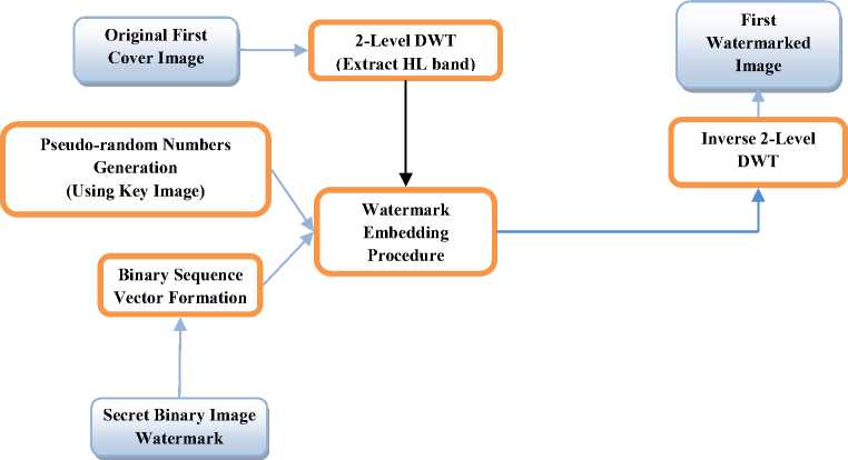
Fig.6. Stage-1 Watermarking Process (Blind)
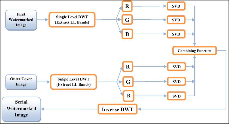
Fig.7. Stage-2 Watermarking Process (Non-Blind)
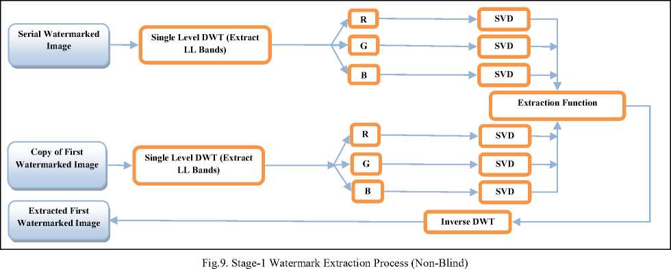
The Fig.9 depicts the Stage-1 of serial watermark extraction process. Here Separation function is for extracting first watermarked image from the serial watermarked image. To frame separation function, apply single level DWT on the copy of first watermarked image to get LL subband which contains most of the image information including hidden information. Then extract R, G and B channels from LL subband. Apply SVD separately on each of R, G and B channel extracted from LL subband of copy of first watermarked image to get S matrices on SR, SG , and SB channels separately and similarly get for U and V matrices also. Same procedure is applied on serial watermarked image also. Then
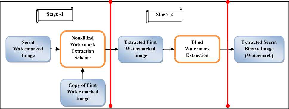
Fig.8. Composite scheme for serial watermark extraction
Extracted Watermark (Secret Binary Image)

Fig.10. Stage-2 Watermark Extraction Process (Blind)
subtract copy of first watermarked image’ (SR, SG and SB) matrices from serial watermarked image’ (SR, SG and SB) matrices respectively to get embedded first watermarked image’ (SR, SG and SB). Multiply the respective U, V matrices to get complete embedded first watermarked image (*Because of the nature of non-blind watermarking technique “copy of first watermarked image”, “serial watermarked image” are taken here to get embedded “first watermarked image” from serial watermarked image). This whole process is presented in stage-1 of Algorithm-2. Then apply 2-level DWT on extracted first watermarked image to locate HL2 sub-bands using Haar wavelets. Compute pseudo-random sequence generated with the help of key image used in the watermark embedding process. Scan the HL2 subband image using a pre-defined block of size 4×4 binary sequence coefficients. Calculate the correlation of the binary sequence block to pseudorandom sequence with extracted binary sequence coefficients and move to next block. This will lead to watermark extraction and is depicted in Fig.10 and details in stage-2 of Algorithm 2.
Algorithms
Abbreviations used in the algorithms
FCI - First Cover Image
SBI - Secret Binary Image
FWI - First Watermarked Image
SCI - Second Cover Image
SWI - Serial Watermarked Image
R, G, B - Red, Green, Blue channels of input color image
U, S, V - U - Left singular vectors, S - Diagonal singular vectors, V - Right singular vectors of SVD
Algorithm 1: Watermark Embedding
Input : i. First cover image (FCI).
-
ii. Secret binary image (SBI).
-
iii. Second cover image (SCI)
Output : Serial Watermarked image (SWI).
Stage-1
Start
Step.1: Decompose the FCI into four non-overlapping sub-bands using haar discrete wavelet transformation: LL1FCI, HL1FCI, LH1FCI, and HH1FCI.
Step.2: Apply haar DWT again to sub-band HL1FCI to get four smaller sub-bands and select the HL2 HL FCI sub-band.
Step.3: Divide the sub-band HL2 HL FCI into predefined binary sequence structure of 4 × 4 blocks.
Step.4: Re-formulate the SBI image into a vector of zeros and ones.
Step.5: Generate two uncorrelated pseudorandom sequences of SBI. One sequence is used to embed the watermark bit 0 and the other sequence is sued to embed the watermark bit 1.
Step.6: Embed the two pseudorandom sequences; sequence 0 and sequence 1, with a gain factor some k , 4 × 4 blocks of the selected DWT subbands of the FCI.
If the secret watermark image bit is 0 then
X '= X + k × pseudorandom sequence for 0 otherwise,
X '= X + k × pseudorandom sequence for 1
[ Where X ' represents the pseudorandom sequence embedded block. X denotes the matrix of the coefficients of block. ]
Step.7: Apply the inverse DWT on the modified subband, to produce the FWI.
Stage-2
Step.8: Decompose the FWI into four sub-bands: FWILL, FWIHL, FWILH, and FWIHH using Haar DWT.
Step.9: Get R, G, and B components from FWILL as R (FWILL), G (FWILL) and B (FWILL)
Step.10: Apply SVD to each of R (FWILL), G (FWILL) and B (FWILL) of Step 9. to get
U(R(FWILL)), U(G(FWILL)) and U(B (FWILL)) S(R(FWILL)), S(G(FWILL)) and S(B (FWILL))
V(R(FWILL)), V(G(FWILL)) and V(B (FWILL)) Step.11: Repeat Step.8 to Step.10 for SCI also to get
U(R(SCILL)), U(G(SCILL)) and U(B (SCILL)) S(R(SCILL)), S(G(SCILL)) and S(B (SCILL)) V(R(SCILL)), V(G(SCILL)) and V(B (SCILL))
Step.12: Now compute (Combining Function)
S_new_R = (S(R(SCILL))) + (S(R(FWILL)) × gain_factor_2)
S_new_G = (S(G(SCILL))) + (S(G(FWILL)) × gain_factor_2)
S_new_B = (S(B (SCILL))) + (S(B (FWILL)) × gain_factor_2)
WI_R = U(R(SCILL)) × S_new_R× V(R(SCILL))
WI_G = U(G(SCILL)) × S_new_G×V(G(SCILL))
WI_B = U(B (SCILL)) × S_new_B × V(B
(SCILL))
newhost_LL= Concatnate (WI_R, WI_G, WI_B) Step.13: Apply inverse Haar DWT on newhost_LL to get SWI
Stop.
The Algorithm 1 uses blind watermarking technique in Stage-1 to embed secret binary image into first cover image and Non-blind watermarking technique in Stage-2 to embed first watermarked image into second cover image.
Algorithm 2: Watermark extraction
Input: i. Serial Watermarked image
-
ii. Copy of First watermarked image
Output: Extracted secret binary image Stage-1
Start
Step.1: Decompose the FWI into four sub-bands: FWILL, FWIHL, FWILH, and FWIHH using Haar DWT.
Step.2: Get R, G, and B components from FWILL as R (FWILL), G (FWILL) and B (FWILL)
Step.3: Apply SVD to each of R (FWILL), G (FWILL) and
B (FWILL) of Step 9. to get
U(R(FWILL)), U(G(FWILL)) and U(B (FWILL)) S(R(FWILL)), S(G(FWILL)) and S(B (FWILL)) V(R(FWILL)), V(G(FWILL)) and V(B (FWILL))
Step.4: Repeat Step.1 to Step.3 for SWI also to get U(R(SWILL)), U(G(SWILL)) and U(B (SWILL)) S(R(SWILL)), S(G(SWILL)) and S(B (SWILL)) V(R(SWILL)), V(G(SWILL)) and V(B (SWILL))
Step.5: Now compute (Extraction Function)
S_new_R = (S(R(SWILL)) - S(R(FWILL)))
/Const
S_new_G = (S(G(SWILL)) - S(G(FWILL)))
/Const
S_new_B = (S(B (SWILL)) - S(B (FWILL)))/ Const
E_FWI_R = U(R(FWILL)) × S_new_R ×
V(R(FWILL))
E_FWI_G = U(G(FWILL)) × S_new_G ×
V(G(FWILL))
E_FWI_B = U(B (FWILL)) × S_new_B × V(B (FWILL))
newhost_LL= Concatenate (E_FWI_R,
E_FWI_G, E_FWI_B)
Step.6: Apply inverse Haar DWT on newhost_LL to get E_FWI
Stage-2
Step.7: Decompose the E_FWI of step 6 into four nonoverlapping multi-resolution subbands: LL1E_FWI, HL1E_FWI, LH1E_FWI, and HH1E_FWI using DWT.
Step.8: Apply DWT to HL1E_FWI to get four smaller subbands, and choose the sub-band HL2E_FWI.
Step.9: Divide the sub-band HL2E_FWI into predefined binary sequence structure of 4 × 4 blocks.
Step.10: Regenerate the two pseudorandom sequences for 0 and 1 using the same seed used in the watermark embedding procedure of Stage-1.
Step.11: For each block in the sub-band HL2E_, calculate the correlation between the elements coefficients and the two generated pseudorandom sequences for 0 and 1.
If the correlation with the pseudorandom sequence 0 was higher than the correlation with pseudorandom sequence 1, then the extracted watermark bit is considered 0
Otherwise the extracted watermark is considered 1.
Step.12: Reconstruct the watermark using the extracted watermark bits, and compute the similarity between the original and extracted watermarks.
Stop.
The Algorithm 2 uses the Non-blind watermarking technique in Stage-1to extract first watermarked image from the second image and Blind watermarking technique in Stage-2 to extract the secret image from first watermarked image. The abbreviations used in the algorithm are mentioned in the beginning of the Algorithm part.
-
IV. Results and Discussions
The scheme proposed here is a robust digital image watermarking scheme which can be more suitable for various applications. The proposed scheme is non-reversible digital image watermarking which cannot restore the original image but it restores original watermark (secret binary image) in a lossless manner for no attacks but it also recovers the original secret binary image (watermark) in a case of various attacks. Moreover, the proposed method uses both blind and non-blind techniques to embed the watermark into a cover image. The blind watermarking technique proposed here needs a key to embed a secret binary image into the first cover image to get the first watermarked image. The first watermarked image is embedded into the second cover image to get serial watermarked image. The performance of proposed scheme has been evaluated in terms of quality of the watermarked image by computing peak signal to noise ratio (PSNR) and robustness of the watermarked image by measuring correlation. Table.1
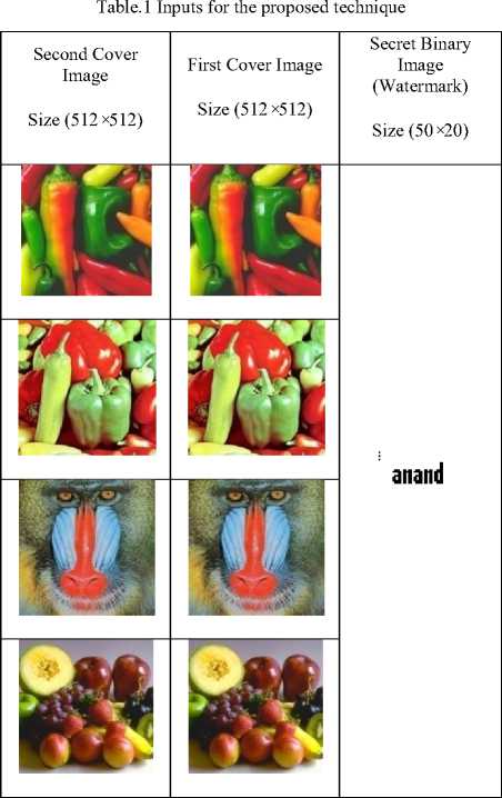
shows the images considered here for testing the proposed scheme. The color images of size 512 × 512 as a first cover image, second cover image and the binary image of size 50 × 20 is considered as a secret binary image (watermark). For copyright protection, security of the secret image is an important factor.
Analysis of security
One of the important indicators of watermarking system is security; if it is insecure then definitely it loses its value for practical applications. The proposed scheme achieves the security parameter effectively, including the position of embedding a secret binary image into first cover image and procedure to embed. The stage-1 of watermark embedding procedure uses HL sub-bands of the first cover image by DWT to hide the binary image (secret binary image vector of 0 and 1) using key and 4×4 binary sequence block mapped on to HL sub-band image of the first cover image. The stage-2 of watermark embedding procedure takes the first watermarked image, second cover image and extracts LL sub-bands by DWT. The R, G and B channels are extracted from LL subbands of both first watermarked image and second cover image. The SVD [12] is applied to R, G and B of each of first watermarked image, second cover image and combining the diagonal singular values of each image to get serial watermarked image. Similarly while extracting the secret binary image we need a copy of first watermarked image and serial watermarked image are needed to get a first watermarked image which contains a secret binary image. Then by using a secret key, the secret binary image can be extracted as it is. The major disadvantage of using SVD and in connection with nonblind technique is the production of false positive/negative error [18]. The root cause of the false-positive/negative problem is that the SVD vectors U and V influence the watermark being extracted from the watermarked image [12] [18][20][21]. This cause will extract the secret binary image as it is from serial watermarked image in spite of various noise attacks.
Analysis of Fidelity (Imperceptibility)
The perceptual similarity between the second cover image and serial watermarked image can be verified by measuring Peak Signal-to-Noise Ratio (PSNR) (Eq. 6) in decibels (dB). Table.2 and Table.3 shows the results of serial watermarking scheme and advantages of combining blind and non-blind techniques. Table.2 and Table.3 also shows the extracted secret binary image (watermark), a correlation between original watermark and extracted watermark. When the same type of first cover image and second cover image are used for serial digital image watermarking, we got the perceptual similarity as PSNR = Infinity dB. The effect of different first cover image and second cover image on perceptual similarity is also noted in Table.2 and Table.3. The image here with 8 bits per pixel contains integers from 0 to 255 (B) PSNR will be given as eq.6.
PSNR = 20loglo (2 B -1) (6)
VMSe
The mean square error (MSE) is the squared norm of the difference between the data x and the approximation x divided by the number of elements.
Where
MSE = ^_У2
To compare the correlation between original secret binary image (watermark) and extracted secret binary image (watermark) we use the formula as depicted in eq.7.
_ Si (xt-xm)(yt-ym)
VS i C^ i- ^ m )2VS i CV i- У т )2
Where x i and y i are intensity values of ith pixel of an original secret binary image and extracted secret binary image, xm and ym are the mean intensity values of an original secret binary image and the extracted secret binary image.
The results shown in Table.2 and Table.3 are presented by varying the gain factor in both stage-1 and stage-2 of the proposed scheme. When we increase the gain factor in stage-1 of watermarking process, it provides more strength (intensity is increased) to the hidden binary image leading to security. When we decrease the gain factor in stage-2, it leads to the decrease of the intensity value of first watermarked image; so when we embed first watermarked image into a second cover image, the perceptual similarity between serial watermarked image and second cover image increases.
Table.2 The results of Composite Serial Digital Image Watermarking (Varying Stage-1 Gain factor and keeping Stage-2 Gain factor constant)
|
First Cover Image |
Secret Binary Image |
First Watermarke d Images |
Second Cover Image |
Serial Watermarked Image |
Perceptual Similarity Between Second Cover Image and Serial Watermarked Image PSNR in dB (Proposed Scheme) |
Correlation Between Secret Watermark and Extracted Secret Watermark (Proposed Scheme) |
|
Stage-1 Gain factor = 10 |
Stage-2 |
Gain factor = 1/10 |
||||
|
$ |
25.6160 |
0.6635 |
||||
|
anand |
$ |
26.4218 |
0.5040 |
|||
|
66 |
^ |
$ |
26.9022 |
0.8157 |
||
|
$ |
$ |
28.0664 |
0.9296 |
|||
|
Stage-1 Gain factor = 50 |
Stage-2 Gain |
factor = 1/10 |
||||
|
anand |
$ |
25.6176 |
0.9931 |
|||
|
96 |
26.4219 |
0.9965 |
||||
|
iff |
iff |
96 |
26.9071 |
1.0000 |
||
|
96 |
96 |
96 |
28.0721 |
1.0000 |
||
|
Stage-1 Gain factor = 100 Stage-2 Gain factor = 1/10 |
||||||
|
^ |
anand |
•г |
96 |
96 |
25.6252 |
1.0000 |
|
96 |
26.4258 |
1.0000 |
||||
|
iff |
iff |
96 |
26.9169 |
1.0000 |
||
|
96 |
96 |
96 |
28.0836 |
1.0000 |
||
Table 3. The results of Composite Serial Digital Image Watermarking (Varying Stage-2 Gain factor and keeping Stage-1 Gain factor constant)
|
First Cover Image |
Secret Binary Image |
First Watermar ked Images |
Second Cover Image |
Serial Watermarked Image |
Perceptual Similarity Between Second Cover Image and Serial Watermarked Image PSNR in dB (Proposed Scheme) |
Correlation Between Secret Watermark and Extracted Secret Watermark (Proposed Scheme) |
|
Stage-1 Gain factor |
100 |
Stage-2 Gain factor = 1/100 |
||||
|
96 |
44.7464 |
1.0000 |
||||
|
г |
anand |
г |
96 |
96 |
45.7965 |
1.0000 |
|
^Jl |
96 |
45.8930 |
1.0000 |
|||
|
96 |
nr |
96 |
47.5332 |
1.0000 |
||
|
Stage-1 Gain factor |
100 |
Stage-2 Gain factor = 1/200 |
||||
|
96 |
51.1832 |
1.0000 |
||||
|
anand |
^ |
96 |
50.4532 |
1.0000 |
||
|
96 |
52.0539 |
1.0000 |
||||
|
96 |
96 |
52.9277 |
1.0000 |
|||
|
Stage-1 Gain factor |
100 |
Stage-2 Gain factor = 1/300 |
||||
|
© |
96 |
53.0417 |
1.0000 |
|||
|
anand |
96 |
96 |
54.2605 |
1.0000 |
||
|
iff |
96 |
53.9710 |
1.0000 |
|||
|
"9Г |
96 |
96 |
54.8236 |
1.0000 |
||
|
Stage-1 Gain factor = 100 Stage-2 Gain factor = 1/500 |
||||||
|
anand |
IK |
IK |
59.0994 |
1.0000 |
||
|
u |
г. |
IK |
68.9811 |
1.0000 |
||
|
65.5147 |
1.0000 |
|||||
|
66.7492 |
1.0000 |
|||||
|
Stage-1 Gain factor = 100 Stage-2 Gain factor = 1/800 |
||||||
|
anand |
IK |
IK |
74.8890 |
1.0000 |
||
|
IK |
75.3410 |
1.0000 |
||||
|
^ |
i^ |
IK |
75.2263 |
1.0000 |
||
|
« |
IK |
Infinite |
1.0000 |
|||
Table.4 The comparison between perceptual similarity results of proposed scheme and various schemes of reference on different set of cover images and watermarks
|
Perceptual Similarity Between Second Cover Image and Serial Watermarked Image (PSNR in dB) (Proposed Scheme) |
Perceptual Similarity Between Cover Image and Watermarked Image (PSNR in dB) Scheme of Reference 2 |
Perceptual Similarity Between Cover Image and Watermarked Image (PSNR in dB) Scheme of Reference 3 |
Perceptual Similarity Between Cover Image and Watermarked Image (PSNR in dB) Scheme of Reference 4 |
Perceptual Similarity Between Cover Image and Watermarked Image (PSNR in dB) Scheme of Reference 5 |
Perceptual Similarity Between Cover Image and Watermarked Image (PSNR in dB) Scheme of Reference 6 |
|
25.6160 |
42.5213 |
49.8664 |
26.16 |
48.16 |
|
|
To |
To |
To |
58.91 |
To |
To |
|
75.2263 |
48.3773 |
50.0839 |
57.01 |
48.99 |
Table.5 The comparison between proposed watermark extraction scheme and various schemes of reference on different set of cover images and watermarks
Table.4 shows the range of PSNR values on various types of images with other schemes presented in reference and Table.5 shows the range of correlation between various types of watermarks and extracted watermarks with other schemes presented in the reference. The proposed scheme uses two stage watermarking scheme that is the content embedded in serial watermarked image is the combination of secret binary image and first cover image. Hence from Table.3, it can be observed that the PSNR values of proposed scheme are lesser than the range from other schemes.
Capacity Analysis
In the case of blind watermarking technique of stage-1, the original first cover image is of size 512×512, after applying 2-level DWT we get the image of size 128×128, then by 4×4 block processing technique giving the total 1024 blocks. Hence here the small secret binary image of size 50×20 is considered. However non-blind watermarking technique of stage-2 uses two images (first watermarked image and second cover image) of the same size and one level DWT, SVD on both of the input images.
Robustness Analysis
|
Correlation Between Secret Binary Image (Watermark) and Extracted Secret Binary Image (Watermark) (Proposed Scheme) |
Correlation Between Watermark and Extracted Watermark (Scheme of Reference 3) |
Correlation Between Watermark and Extracted Watermark (Scheme of Reference 4) |
Correlation Between Watermark and Extracted Watermark (Scheme of Reference 5) |
Correlation Between Watermark and Extracted Watermark (Scheme of Reference 6) |
|
1.0000 |
1.0000 |
1.0000 |
1.0000 |
1.0000 |
Table.6 The result of secret binary image extraction process on various attacks
|
Test Inputs |
|||||
|
First Cover Image |
Secret Binary Image |
Second Cover Image |
Serial Watermarked Image |
||
|
anand |
|||||
|
Correlation Between Secret Watermark and Extracted Secret Watermark (Proposed Scheme) |
|||||
|
Attack Type on Serial Watermarked Image |
Stage 1 Gain factor = 10 Stage 2 Gain factor = 1/10 |
Stage 1 Gain factor = 50 Stage 2 Gain factor = 1/10 |
Stage 1 Gain factor = 100 Stage 2 Gain factor = 1/10 |
||
|
Gaussian Noise |
0.6559 |
0.9931 |
1.0000 |
||
|
Speckle Noise |
0.6409 |
0.9931 |
1.0000 |
||
|
Salt & Pepper Noise |
0.6525 |
0.9931 |
1.0000 |
||
|
Poisson Noise |
0.6618 |
0.9931 |
1.0000 |
||
|
Rotation (900) |
0.6635 |
0.9931 |
1.0000 |
||
|
Rotation (1800) |
0.6635 |
0.9931 |
1.0000 |
||
|
Rotation (2700) |
0.6635 |
0.9931 |
1.0000 |
||
|
JPEG Compression |
0.6615 |
0.9931 |
1.0000 |
||
|
Cropping 25%, 50% and 75% |
0.6635 |
0.9931 |
1.0000 |
||
Table.7 The result of secret binary image extraction process on various attacks
|
Test Inputs |
|||||
|
First Cover Image |
Secret Binary Image |
Second Cover Image |
Serial Watermarked Image |
||
|
ГВ |
anand |
||||
|
Correlation Between Secret Watermark and Extracted Secret Watermark (Proposed Scheme) |
|||||
|
Attack Type on Serial Watermarked Image |
Stage 1 Gain factor = 100 Stage 2 Gain factor = 1/100 |
Stage 1 Gain factor = 100 Stage 2 Gain factor = 1/200 |
Stage 1 Gain factor = 100 Stage 2 Gain factor = 1/300 |
Stage 1 Gain factor = 100 Stage 2 Gain factor = 1/500 |
Stage 1 Gain factor = 100 Stage 2 Gain factor = 1/800 |
|
Gaussian Noise |
1.0000 |
1.0000 |
1.0000 |
1.0000 |
1.0000 |
|
Speckle Noise |
1.0000 |
1.0000 |
1.0000 |
1.0000 |
1.0000 |
|
Salt & Pepper Noise |
1.0000 |
1.0000 |
1.0000 |
1.0000 |
1.0000 |
|
Poisson Noise |
1.0000 |
1.0000 |
1.0000 |
1.0000 |
1.0000 |
|
Rotation (900) |
1.0000 |
1.0000 |
1.0000 |
1.0000 |
1.0000 |
|
Rotation (1800) |
1.0000 |
1.0000 |
1.0000 |
1.0000 |
1.0000 |
|
Rotation (2700) |
1.0000 |
1.0000 |
1.0000 |
1.0000 |
1.0000 |
|
JPEG Compression |
1.0000 |
1.0000 |
1.0000 |
1.0000 |
1.0000 |
|
Cropping 25%, 50% and 75% |
1.0000 |
1.0000 |
1.0000 |
1.0000 |
1.0000 |
|
The range of Correlation Between Watermark and Extracted Watermark (On different set of color cover images and watermarks) |
||||
|
Proposed Scheme |
Scheme of Reference 3 |
Scheme of Reference 4 |
Scheme of Reference 5 |
Scheme of Reference 6 |
|
1.0000 to 1.0000 |
0.86 to 1.0000 |
0.56 to 1.0000 |
0.487 to 1.0000 |
0.760 to 0.997 |
-
[10] Hierarchical Recovery for Tampered Images Based on Watermark Self-Embedding. Displays .
-
[11] Qin, C., Wang, H., Zhang, X., & Sun, X. (2016). Selfembedding fragile watermarking based on reference-data interleaving and adaptive selection of embedding mode. Information Sciences , 373 , 233-250.
-
[12] Ansari, I. A., & Pant, M. (2016). Multipurpose image watermarking in the domain of DWT based on SVD and ABC. Pattern Recognition Letters .
-
[13] Sheth, R. K., & Nath, V. V. (2016, April). Secured digital image watermarking with discrete cosine transform and discrete wavelet transform method. In Advances in Computing, Communication, & Automation
(ICACCA)(Spring), International Conference on (pp. 1-5). IEEE.
-
[14] Ali Al-Haj (2007) Combined DWT-DCT Digital Image Watermarking. Journal of Computer Science, 3 (9), 740746, ISSN: 1549-3636.
-
[15] http://in.mathworks.com/matlabcentral/fileexchange/4505 2-color-image–dwt–svd-watermarking.
-
[16] Xia, X. G., Boncelet, C. G., & Arce, G. R. (1998). Wavelet transform based watermark for digital images. Optics Express , 3 (12), 497-511.
-
[17] Cox, I., Miller, M., Bloom, J., Fridrich, J., & Kalker, T. (2007). Digital watermarking and steganography . Morgan Kaufmann.
-
[18] Zear, A., Singh, A. K., & Kumar, P. (2016). A proposed secure multiple watermarking technique based on DWT, DCT and SVD for application in medicine. Multimedia Tools and Applications , 1-20.
-
[19] Anuja Dixit & Rahul Dixit. (2017). "A Review on Digital Image Watermarking Techniques." International Journal of Image, Graphics and Signal Processing (MECS) 9, no. 4: 56-66.
-
[20] Subin Bajracharya & Roshan Koju. "An Improved DWT-SVD Based Robust Digital Image Watermarking for Color Image. (2017) " International Journal of
Engineering and Manufacturing (IJEM) (MECS) 7, no. 1: 49-59.
-
[21] Gökçen Çetinel, LLukman Çerkezi. "Robust Chaotic Digital Image Watermarking Scheme based on RDWT and SVD. (2016) " International Journal of Image,
Graphics and Signal Processing (MECS) 8, no. 8: 58-67.
-
[22] Gunjal, Baisa L. "Robust, Secure and High Capacity Watermarking Technique based on Image PartitioningMerging Scheme. (2016) " International Journal of
Information Technology and Computer Science (MECS) 8, no. 4: 74-85.
-
[23] Kaiser J. Giri, Mushtaq Ahmad Peer, P. Nagabhushan. (2015) "A Robust Color Image Watermarking Scheme Using Discrete Wavelet Transformation." International Journal of Image, Graphics and Signal Processing (MECS) 7, no. 1: 47-52.
References Serial digital color image watermarking using composite scheme
- Liu, X., Han, G., Wu, J., Shao, Z., Coatrieux, G., & Shu, H. (2017). Fractional Krawtchouk transform with an application to image watermarking. IEEE Transactions on Signal Processing.
- Hua, K. L., Dai, B. R., Srinivasan, K., Hsu, Y. H., & Sharma, V. (2017). A hybrid NSCT domain image watermarking scheme. EURASIP Journal on Image and Video Processing, 2017(1), 10.
- Su, Q., & Chen, B. (2017). Robust color image watermarking technique in the spatial domain. Soft Computing, 1-16.
- Kandi, H., Mishra, D., & Gorthi, S. R. S. (2017). Exploring the learning capabilities of convolutional neural networks for robust image watermarking. Computers & Security, 65, 247-268.
- Abdelhakim, A. M., Saleh, H. I., & Nassar, A. M. (2017). A quality guaranteed robust image watermarking optimization with Artificial Bee Colony. Expert Systems with Applications, 72, 317-326.
- Wang, C., Wang, X., Zhang, C., & Xia, Z. (2017). Geometric correction based color image watermarking using fuzzy least squares support vector machine and Bessel K form distribution. Signal Processing, 134, 197-208.
- Etemad, E., Samavi, S., Soroushmehr, S. R., Karimi, N., Etemad, M., Shirani, S., & Najarian, K. (2017). Robust image watermarking scheme using bit-plane of hadamard coefficients. Multimedia Tools and Applications, 1-23.
- Qin, C., Ji, P., Wang, J., & Chang, C. C. (2017). Fragile image watermarking scheme based on VQ index sharing and self-embedding. Multimedia Tools and Applications, 76(2), 2267-2287.
- Zhang, Z., Wu, L., Yan, Y., Xiao, S., & Sun, H. (2017). An improved reversible image watermarking algorithm based on difference expansion. International Journal of Distributed Sensor Networks, 13(1), 1550147716686577.
- Hierarchical Recovery for Tampered Images Based on Watermark Self-Embedding. Displays.
- Qin, C., Wang, H., Zhang, X., & Sun, X. (2016). Self-embedding fragile watermarking based on reference-data interleaving and adaptive selection of embedding mode. Information Sciences, 373, 233-250.
- Ansari, I. A., & Pant, M. (2016). Multipurpose image watermarking in the domain of DWT based on SVD and ABC. Pattern Recognition Letters.
- Sheth, R. K., & Nath, V. V. (2016, April). Secured digital image watermarking with discrete cosine transform and discrete wavelet transform method. In Advances in Computing, Communication, & Automation (ICACCA)(Spring), International Conference on (pp. 1-5). IEEE.
- Ali Al-Haj (2007) Combined DWT-DCT Digital Image Watermarking. Journal of Computer Science, 3(9), 740-746, ISSN: 1549-3636.
- http://in.mathworks.com/matlabcentral/fileexchange/45052-color-image–dwt–svd-watermarking.
- Xia, X. G., Boncelet, C. G., & Arce, G. R. (1998). Wavelet transform based watermark for digital images. Optics Express, 3(12), 497-511.
- Cox, I., Miller, M., Bloom, J., Fridrich, J., & Kalker, T. (2007). Digital watermarking and steganography. Morgan Kaufmann.
- Zear, A., Singh, A. K., & Kumar, P. (2016). A proposed secure multiple watermarking technique based on DWT, DCT and SVD for application in medicine. Multimedia Tools and Applications, 1-20.
- Anuja Dixit & Rahul Dixit. (2017). "A Review on Digital Image Watermarking Techniques." International Journal of Image, Graphics and Signal Processing (MECS) 9, no. 4: 56-66.
- Subin Bajracharya & Roshan Koju. "An Improved DWT-SVD Based Robust Digital Image Watermarking for Color Image. (2017) " International Journal of Engineering and Manufacturing (IJEM) (MECS) 7, no. 1: 49-59.
- Gökçen Çetinel, LLukman Çerkezi. "Robust Chaotic Digital Image Watermarking Scheme based on RDWT and SVD. (2016) " International Journal of Image, Graphics and Signal Processing (MECS) 8, no. 8: 58-67.
- Gunjal, Baisa L. "Robust, Secure and High Capacity Watermarking Technique based on Image Partitioning-Merging Scheme. (2016) " International Journal of Information Technology and Computer Science (MECS) 8, no. 4: 74-85.
- Kaiser J. Giri, Mushtaq Ahmad Peer, P. Nagabhushan. (2015) "A Robust Color Image Watermarking Scheme Using Discrete Wavelet Transformation." International Journal of Image, Graphics and Signal Processing (MECS) 7, no. 1: 47-52.
