Shape Design of Lifting body Based on Genetic Algorithm

Author: Yongyuan Li, Yi Jiang, Chunping Huang
Journal: International Journal of Information Engineering and Electronic Business(IJIEEB) @ijieeb
Article in issue: 1 vol.2, 2010.
Free access
This paper briefly introduces the concept and history of lifting body, and puts forward a new method for the optimization of lifting body. This method has drawn lessons from the die line design of airplane is used to parametric numerical modeling for the lifting body, and extract the characterization of shape parameters as design variables, a combination of lifting body reentry vehicle aerodynamic conditions, aerodynamic heating, volumetric Rate and the stability of performance. Multi-objective hybrid genetic algorithm is adopted to complete the aerodynamic shape optimization and design of hypersonic lifting body vehicle when under more variable and constrained condition in order to obtain the Pareto optimal solution of Common Aero Vehicle shape.
Lifting Body, Multi-objective Genetic Algorithm, Optimization Design
Short address: https://sciup.org/15013046
IDR: 15013046
Text of the scientific article Shape Design of Lifting body Based on Genetic Algorithm
Published Online November 2010 in MECS
-
I. I NTRODUCTION
In the early 1950s, the concept of lifting body reentry from suborbital or orbital space flight evolved at National Advisory Committee for Aeronautics (NACA) Ames Aeronautical Laboratory, Moffett Field, California, by two imaginative engineers, Allen and Alfred Eggers. The initial work was accomplished in connection with the reentry survival of ballistic missile nose cones1. Mr. Allen found that by blunting the nose of a missile, the reentry energy would be more rapidly dissipated through the large shock wave while a sharp nosed missile would absorb more energy, in the form of heat, through skin friction. the blunt-nosed vehicles were more likely to survive while the pointed nosed vehicles may suffer severe damage form heating. More importantly, they observed that the flat upper surface of cone through the earth's atmosphere can generate lift, and increase the aerodynamic stability2. From 1963 to 1975, the United States National Aeronautics and Space Administration (NASA) conducted a series of selection studies for recoverable spacecraft; the basic design is the lifting body. United States National Aeronautics (NASA) and Air Force (USAF) had been carried out 225 flight tests for the lifting body configuration aircraft. These flight tests includes M2-F2 and HL-10 series that NASA research and the Air Force's X-24 series and X-33, X-34, X37 and X38 series3.
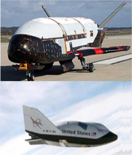
Fig.1 The space shuttle and X-38 of US
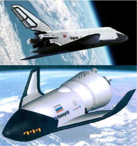
Fig 2 "Buran" space shuttle and "Clipper" space orbital vehicle
Besides the United States, Soviet Union's "Buran" space shuttle4, "Clipper" space orbital vehicle5 were adopted the lifting body design. Japan and Europe, many of the manned transport aircraft also adopted lifting body configuration, such as HYFLEX test vehicle shape of Japan Aerospace Exploration Agency3, 6, 7 (JAXA), the sub-orbital Hopper Aircraft Configuration of Europe Space Agency (ESA), EXPERT test vehicle shape, IXV test vehicle shape, SOCRATES8 test vehicle shape.
There is no typical lifting body configuration aircrafts in our country currently except the message that Crossentry vehicle have been successful test flight that from Shaanxi TV, but the message has not been further confirmed by authorities. Shape of this Cross-entry vehicle is similar to X-37 aircraft shape, and its nose cone and wing leading edge are made of CISC Ceramic composite materials, its shape as shown in Figure 3.In addition, Lifting body aircraft design in domestic are at the conceptual design phase, many universities and research institutes start the related research. Reference [10] in order to improving its low speed aerodynamic performance and investigating effects of various aerodynamic factors, Wind tunnel experiments of a saucer-like low speed lifting-body were conducted. Reference [11] uses Zhang Hanxin’s NND scheme to study the aerodynamic and aero thermal character of a lifting body like X-33 of America. Reference [12] uses adaptation of QUICK schemes under uneven grids to the calculations of strongly separated turbulent flow. Overall, the study about lifting body configuration aircraft is less than the other developed countries.
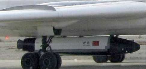
Fig.3 Cross-entry vehicle
Lifting body configuration vehicle has become the
first-selected scheme of orbital vehicle due to its favorable aerodynamics characteristics during high angle of attack and hypersonic speed situation, its efficient utilization ratio of internal volume, its characteristics of reentry physics such as high fever load and low heat flux rate. Lifting body configuration vehicle adopts bluntnosed cones body, while without the main wing structure which most aircrafts have. Its flat part of cone body surface can produce lift force while passing through atmosphere and meanwhile enhance aerodynamic stability. During the stage of concept research and scheme design of orbital vehicle, traditional wind tunnel for type selection has many disadvantages, such as heavy work, long design period and poor economic benefits; it cannot obtain genuine optimum shape either. In contrast, with the use of assistant design by computer and optimization theory during the multi-objective optimization of vehicle configuration design, the vehicle's overall performance can be greatly enhanced, which of course still needs further confirmation by wind tunnel tests. According to the design indexes and mission requirements of orbital vehicle, comprehensive consideration must be taken during the arrangement design in order to meet relevant design conditions and design indexes as constraints, and to ensure the optimized aerodynamic configuration meet these conditions. This paper first establishes geometric modeling for Lifting body configuration of orbital vehicle, then adopts multiobjective hybrid genetic algorithm for multi-objective optimization of its shape design, to obtain Pareto optimal solutions of orbital vehicle configuration.
-
II. NUMERICAL MODELING FOR SHAPE OF ORBITAL VEHICLE
Compared with the traditional layout of aircraft, lifting body configuration does not have the major component-conventional wings; it produces lift force by using the three-dimensional design of the wing-body fusion instead. This design can not only eliminate the additional torque of the fuselage and other parts, but also eliminate the interference between wings and fuselage, thus a higher lift-drag ratio will be obtained to improve vehicle’s performance. The lifting body configuration can be mainly divided into three parts, the fuselage, the rudder and the elevon. The basic configuration is shown in Fig. 4.
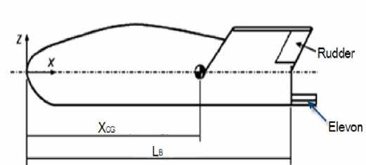
Fig 3 Body side view of the basic configuration
The fuselage structure of orbital vehicle is different from that of the conventional aircraft. Due to the special use of the flying wing structure, its body can be divided into two parts, the first part which is called middle fuselage is the same as the conventional; the second part are the flying wings by both sides of the fuselage. To ensure the longitudinal body surface of the vehicle be smooth, the method of modulo line design is adopted, that is, to divide vehicle along the vertical into a number of vertical control stations and to produce different crosssectionals design of control points according to certain needs at each station, then connect those cross-sectionals by a smooth vertical curve, thus the remaining crosssectionals can be generated from the vertical control lines which is produced by these control stations. The shape of the cross-section is obtained by using the conic generated from the plane oblique cutting cone, which can construct circular, elliptic, parabolic and hyperbolic, to design the structure of typical vehicle conic section shape simply and precisely. The general form of quadratic equation is as follows:
aX 2 + bXY + CY 2 + dX + eY + f = 0 (1)
As is shown in Fig. 5, suppose the starting point A as intersection point of vehicle fuselage in the vertical plane and cross-section at the leeward side, the end point B of the second curve is the intersection of horizontal and cross-section, while point C as intersection point of the tangent line through point A and that through point B, thus, Conic shape that within the plane ABC through point A, point B will be controlled by the location of shoulder point E. If the point D is the midpoint of line AB and then the second curve shape parameter p is introduced, and p =LDE/LDC, so the location of shoulder point E can be determined by making the shape parameter p value only, thus the second curve is also made only to determine the shape of AEC, which determines uniquely the shape of the vehicle 12, 13.
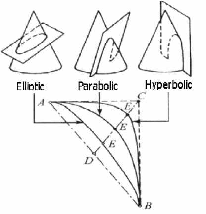
Fig. 5 The conic schematic Diagram of plane cut cone
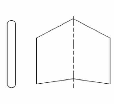
Fig. 6 The Airfoil profile and the planform
The shape of cross-section middle fuselage is determined by the following five parameters in this article, they are control point radius r 1 of Leeward meridian for 0 degree, control point radius r 2 of lateral meridian for 90 degree, control point radius r 3 of windward meridian for 180 degree, shape parameter p i of conic for upper middle fuselage and shape parameter p of conic for downward middle fuselage.
The structure of flying wing is similar to the structure of general oblique wing, so the shape of flying wing can be described with the shape parameters of general oblique wing. The selection of planform for flying wing is the shape of swept wing, the selection of airfoil profile is hexagonal airfoil, and the wing tip should be deactivated. The airfoil treated on those conditions is shown in Fig. 6. The geometric parameters of the flying wing include the aspect ratio X , the taper of the flying wing n , swept-leading-edge angle xo and the flying wing area S . To ensure the stability for pitch, the flying wing must be with about 15% of the relative thickness, in this way, there will be enough space to install the remote control device, fuel tanks and engines, and the excessive flow separation caused by excessive thickness of the back can be avoided as well.
The flight control of Common Aero Vehicle can be realized with a pair of rudders and elevons. In specific, the rudders are installed on both sides of the flying wing, and the elevons are installed on the bottom middle fuselage. Geometric parameters of rudder are as follows: the aspect ratio X f , the taper of the rudder n f , the swept-leading-edge angle x o f and the rudder area Sf . The plane shape of elevon is rectangular, its main parameters are: the aspect ratio Xs , the relative thickness c and the area of control surface Ss . Rudder and elevon control surfaces in the coordinate systems can be converted into the middle fuselage coordinate system.
After the establishment of the middle fuselage, flying wing, rudders and elevons models, and the relative position of the flying wings in the layout of the middle fuselage can be determined by several control parameters to complete the vehicle’s overall geometric modeling. The control parameters are: the distance Xcw that from the front of the flying wing to the bottom of the middle fuselage, the distance Zcw that from the front of the flying wing to the vertical surface of the middle fuselage and the dihedral angle yxw of oblique.
-
III. M ULTI - OBJECTIVE GENETIC ALGORITHMS
The optimal design with multiple design objectives is in fact a multi-objective mathematical programming problem; the problem can be described as looking for the vector x * for the decision variable, that is, the vector of design variables to optimize the objective function vector f ( x * ) , that is
-
V- min f ( x )=[ f i( x ), f 2( x ), L , fn ( x )] T
< s.t . xeX
X c Rm
Where, V_ min , stands for the vector minimization, that is, the objective function vector f(x)=[fi(x),f,(x)L,fn(x)]T in each sub-objective functions are minimized as much as possible. If the set XcR is a constraint set of the multi-objective optimization model, the f (x)cRm will be the vector objective function of the multi-objective optimization. If there is a solution of x eX , and x is superior to anyX in all the other solutions, the claimed solution x1 is an optimal solution of the multi-objective optimization model. If solution ;qeX , and there is no superior solution than the x1 , claimed, then x1 is a multiobjective optimization model of the Pareto optimal solution.
Common Aero Vehicle is a complex system. The optimization for its overall performance is comprehensive, multi-peaked and strong coupling, etc.; Sensitivity is difficult to solve during the optimization design process; the relationship between the design variables and the performance is complicated so it is difficult to establish a simple and direct mapping. Taken all the above factors into consideration, the traditional local search algorithms is not competent. In order to improve the efficiency of genetic algorithm, this paper makes a series of improvements according to those genetic deceptive problems which genetic algorithms prone to produce. The new algorithm combines the concept of Pareto noninferior solution and the genetic algorithm thinking, and adopts a range of technologies such as real number coding, niche environment out, Qunti sort, steady state reproduction and dynamic punishment to overcome the shortcomings of the standard genetic algorithm, to improve the optimization efficiency. The simulated annealing is introduced in the late evolution for local search, thus the hybrid genetic algorithm is formed, which is suitable for complex multi-objective optimization problems.
IV T HE OPTIMAL DESIGN MODEL OF LIFTING BODY
-
A. Performance Index Calculation
Although multi-objective genetic algorithm can obtain the non-inferior solutions in the global sense, the calculation task is rather heavy. In order to improve the efficiency and optimize the computing speed, this variety of performance indicators are calculated using engineering algorithm. Major performance indicators are computed: aerodynamic performance, aerodynamic heating, capacity utilization and stability.
-
1) Aerodynamic calculation
Based on the hypersonic inviscid flow theory, an amendment is made according to the viscous resistance estimate. Nowadays, there are several types of supersonic, hypersonic engineering estimation methods published both at home and abroad such as Newton's method, modified Newton method, tangent cone method, OSU empirical equation, shock expansion method, DAHLEM-BUCK empirical formula, the explosion method, modified tangent cone method, slender body theory and so on. This paper absorbed the advantages of the calculation methods above, and to provide a reliable engineering algorithm for the aerodynamic calculation of Common Aero Vehicle. By comparing the aerodynamic prediction with test results of the X-38 demonstration aircraft [6], the error between the aerodynamic estimation and testing results is less than 7% at the maximum, which verifies the reliability of aerodynamic calculations. This paper mainly uses these following categories pressure coefficient calculation method.
-
a) Newton pressure calculation formula
C p = 2sin2 5
Hereinto, 5 is the angle that object plane and flow direction.
-
b) Prandtl-Meyer calculation formula
(3) free
Cp =- —5 2 <
V ^ Y +1) Ma
-1
Hereinto, Ma ro is the free stream Mach number.
-
c) VANDYKE calculation formula
Cp =52
Hereinto, H =
-
d) DAHLEM-BUCK calculation formula
2.0sin
2
5
(Г / . x 3/ T x У L . X 5/
{ 1 + ( sin4 5 ) /4 ( 4cos 5 cos2 5 ) 4} ( sin 5 ) /4
: IL J J
CP H
(5 > 22.5o)
-
e) Tangent cone method calculation formula
4 sin2 6 ( 2.5 + 8 V Ma I -1 • sin 6TC ) p 1 +167 Ma ^ - 1 • sin 6TC
Hereinto,
6TC = sin - 1 ( sin 6 cos a + cos 6 sin a sin ф ) f) Expansion wave calculation formula
CP = —— p Y Ma I
Y -1.,
1 +-- Ma sin 5
2 y
Y - 1
-1
-
2) Calculation of aerodynamic heating
Fay-Riddle formula is applied to calculate the aerodynamic heating for stagnation point, while the calculation of aerodynamic heating of non-stagnation point flow and body surface will choose a different formula according to the flow and the surface of the shape, And stagnation temperature can be obtained through the establishment and solution of the heat flow balance equations14, 15.
Fay-Riddle formula qs = 0.763 Pr -°'67
(
P s M s V
s 7
Hereinto, ps is air density of stagnation point behind normal shock wave, ps is viscosity of stagnation point behind normal shock wave viscosity. Velocity gradient of stagnation point as
0.5
2( P s - P 2 )

P s
Lees formula qs = 26 sin 6
f 11. 1
1--r cos 2 6 +-----
V Y Ma 2 J Y Ma 2.
/ D ( 6 )°'5
(11) 3) Capacity utilization calculation
Take the middle fuselage cross section shape as a breakthrough point, extend the cross section profile along the axis of vehicle three-dimensional to get the fuselage surface equation. The surface area and volume available can be got from the integration of the section along the axis, and the capacity utilization rate can be calculated.
Vu = 6 4П • vs 3/2 (12)
Hereinto, V is capacity of vehicle, S is the area of vehicle.
-
4) Stability analysis
To calculate the static stability derivatives, the dynamic stability derivatives and the static stability margin of basic shape (that except a pair rudders and elevons). If the static stability is insufficient, then add to it through the control surface deflection; find out each control surface deflection angle.
-
B. Constraints and design variables
The middle fuselage is the most important component of the Common Aero Vehicle; the shape design is directly related to the overall performance of the vehicle. For the vehicle flying unpowered glide reentry state, the overall performance includes vehicle lift-drag characteristics (described by lift-drag ratio), aerodynamic thermal characteristics of the station point (described by body head stagnation temperature), stability and Fuselage internal volume, etc. Design altitude as 8~30 km, speed 26~6 Ma, voyage greater than 3000 km. Design unpowered glide reentry status as the state. Expect the optimized design of vehicle aerodynamic configuration will maximum the gliding state aerodynamic drag ratio and the utilization of capacity, meanwhile, meet a series of shape constraints and performance constraints.
-
1 ) Constraints
Adopt multi-objective optimization hybrid genetic algorithm to undertake the optimization design of the aerodynamic maximum lift-to-drag ratio under multiconstraints for the vehicle. The main constraints include:
-
(1) The total vehicle length: Lc = 2.61° m.
-
(2) Body stagnation temperature limit: Ts < 147° K.
-
(3) Longitudinal and lateral static stability limit:
Xc <- 6% , Xs < 2% . Longitudinal, lateral overload limit the maximum available: nyk > 1.5 , nzk < 0.5 .
-
(4) Limit the maximum rudder angle: 6 <2°o.
In addition to the constraints above, there are other constraints as control surface position, the flying wing and control surface constraints such as the largest area.
-
2) Design variables
First establish the numerical modeling of General Reentry Vehicle, then extracted shape parameters as design variables, among which, including two parameters of conic shape, flying wing shape parameter, rudder shape parameter, elevon parameters, and a total of 13 design variables.
V O PTIMIZATION
Given that the length of the vehicle is fixed, then seek for the layout scheme under the flight condition that the lift-to-drag ratio K and the volume utilization Vu reach to maximum. The lift-to-drag ratio of the vehicle is the lift coefficient over drag coefficient. The lift coefficient is the sum of the lift coefficient of the rudder and the elevator, and that of the combination of the middle fuselage and its both sides. Likewise, the drag coefficient is the sum of the drag coefficient of the rudder and the elevator and that of the combination mentioned above. The vehicle lift-drag ratio is relative to the attack angle and the rudder angle of the vehicle. Based on a hypersonic vehicle program outline shown in Figure 1, design conditions as: altitude H=30 km, Mach=6, angle of attack = 5 degree, rudder angle = 0 degree, reference length of vehicle = 2.61 m. Set of genetic algorithm population size 500, crossover probability 0.8, mutation probability 0.2, the maximum evolution generation as 400, when evolved to 327 generations, make population convergence. Pareto optimal solution of reentry vehicle is shown in Table 1.
|
Table 1 The Pareto solution of optimal design |
||||
|
Performace |
The cross section of the fuselage |
|||
|
Parabolic |
Circular |
Hyperbolic |
Elliptic |
|
|
K |
3.015 |
2.857 |
2.623 |
2.758 |
|
Vu |
0.6321 |
0.5812 |
0.6321 |
0.5568 |
|
Ts |
1235 |
1190 |
1154 |
1319 |
|
S |
83.424 |
78.944 |
93.056 |
85.048 |
|
V |
625.97 |
614.75 |
595.97 |
605.86 |
|
z ° |
48.81o |
45.57o |
49.35o |
50.21o |
|
n |
1.1052 |
1.1254 |
1.1328 |
1.3542 |
|
x ° f |
57.53o |
52.33o |
60.28o |
54.57o |
|
Vxw |
67.43 o |
65.48 o |
69.35 o |
70.12 o |
Table 1, K stands for the lift-drag ratio when the middle fuselage cross section of the vehicle is respectively parabolic, circular, hyperbolic and elliptic; Vu for the volumetric efficiency, mainly related to vehicle surface area and volume V ; Ts for the vehicle head stagnation temperature in Kelvin, S for the surface area of vehicle in square decimeter; V for the volume of vehicle in cubic decimeter. Table 1 shows such a result, the circular shape cross section has the smallest surface area, while the parabolic shape cross section with the largest volume and its utilization efficiency reaches to maximum; the hyperbolic shape cross section with the lowest stagnation temperature of the head.
In this paper, based on the numerical modeling of
Common Aero Vehicle shape, the performance index calculation and optimization of design, a variety of quadratic cross-section of the layout of the program can be got. The bottom of the cross section is shown in Figure 7.
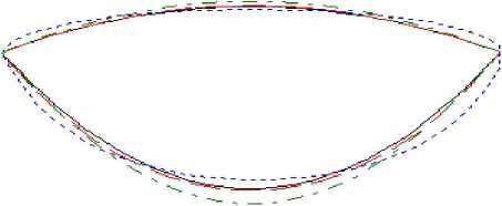
circular ----------- parabolic hyperbolic ........... elliptic
Fig 7 Comparison of optimization results of the cross-section
Fig. 7, represents circular cross section, represents parabolic cross section, represents circular hyperbolic section and represents elliptic cross section. To reflect the optimal design results, select one from the Pareto optimal solution as the shape of Common Aero Vehicle.
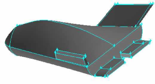
Fig. 8 The shape of optimal configuration
The selection is based on a comprehensive and integrated consideration for various performance indicators, so the major performance indicators can attain to optimization of certain degree simultaneously, without leading serious deterioration to the other indicators, or make a little sacrifice to some performance indicators within the acceptable range to significantly improve those key performance indicators, that is, to sacrifice part interests to maximize the overall interests. There are only a few subtle differences among the Pareto optimal solutions; the paper selected the Pareto solution when the cross-section is parabolic as the recommendation program of the shape design of the Common Aero Vehicle. The contour is shown in Fig 8.
VI CONCLUSIONS AND FUTURE WORK
In this paper, multi-objective hybrid genetic algorithm is applied to the layout design of hypersonic vehicle. The Pareto optimal aerodynamic configuration of the vehicle can be obtained based on the design variables which have been optimized to. The new approach will contribute to improve the water-level of vehicle design and enhance the overall program performance. Moreover, it can be applied to the overall optimal design of similar aircraft.
ACKNOWLEDGMENT
The authors wish to thank all the reviewers for their valuable comments and suggestions that improved the quality of this paper.
References Shape Design of Lifting body Based on Genetic Algorithm
- Robert W. kempel, Weneth D. Painter and Milton O. Thopson. Developing and Flighting Testing. NASA Reference Publication 1332.
- http://baike.baidu.com/view/51947.htm
- Lumin Zhang. Aerodynamics Analysis of Space Shuttle[M]. 2009,Beijing: National Defense Industry of Press.April 1994.
- http://baike.baidu.com/view/38801.htmthe HL-10 Lifting Body: A precursor to the Space Shuttle[M]. NASA Reference Publication 1332.
- http://baike.baidu.com/view/1314400.htm
- Han Pengxin, Cui Naigang, Mu Rongjun, Chen Gong. Survey on Development of RBV in Japan and Europe[J].MISSILESAND SPACE VEHICLES. 2010,308(4):31-36
- Chen Yu-shu, Problems of Hypersonic Vehicle Research[J]. Winged Missiles.Vol.34, No.2, 2006
- http://okzhaosheng.com/okzsw/liuxueyuke/rbfg/20090918124262.html
- Kang Kaihua, Cai Manrui.European Development Program of Next Generation Launch Vehicles[J]. MISSILESAND SPACE VEHICLES. 2008,296(4):26-30
- Wang Jindong, Shen Xialing, Gao Ge. Experimental Research of Low Speed Aerodynamic Characteristics of Saucer-Like Lifting Body[J].Journal of Beijing University of Aeronautics and Astronautics. 2003,29(4):346-349
- LIU Wie, LIU Jun, ZHANG Hanxin Topological Structures’ Analysis for Hypersonic ViscousFlows aroundLiftbody-TyPe[J].CHINESE QUARTERLY OF MECHANICS. 2003,24(3):287-291
- ZENG Xue-jun,LI Ming,LIUTai-kui,Li Si-xin,Peng Zhi-yu. The character research of aerodynamic heating on lifting body model using infrared thermographic technique[J].ACTA
- AERODYNAMICA SINICA. 2004,22(4):494-498.
- JIANG Zhi-guo. Integrated Optim ization Design for aHypersonic Cruise Vehicle[J]. Flight Dynamics. Vol.26, No.1, Feb 2008
- Thomas J.Horvath, Scott A.Berry, and N.Ronald Merski. X-38 Experimental Aerothermodynamics [J].AIAA Journal Vol.41,No.2,March–April 2004
- Qu Zhang-hua. Hypersonic aerodynamics. Changsha: National Defence University Press,2001
- Zhang Zhi-cheng. Hypersonic aerodynamic heating and thermal protection. Beijing: National Defence Industry Press, 2003
- MECS Journal
- Home Latest News & Events Aims and Scope Submit a Paper Author Guidelines Editorial Board Review Process E-Mail Alert Become a Member Indexing Service Publication Charge Recommend to Library Best Paper Awards Terms & Conditions Special Issues Publication Ethics and Malpractice Statement
